2.7
Unsaturated Soils
2.7.1 Introduction to Unsaturated Soils
Historians and librarians have the job of classifying what the rest of us do for a living and when we did it. Art historians write texts defining when famous artists were working in their pink period, their blue period or their charcoal period. Relative to my career, they will probably classify it by the five-year structural period, the 20-year saturated clay period, the 20-year unsaturated sand period, and the 20-year teaching/mentoring period. I started as a structural engineer and went into geotechnical engineering in Ohio where we had saturated clays. I moved to New Mexico and had to learn unsaturated soil mechanics in silty sandy soils. During most of this time, I taught classes in mechanics, structural engineering and geotechnical engineering to students and practicing engineers. Currently I have transitioned into the last 20-year period of mentoring practicing engineers and geotechnical faculty. But no matter what the classification categories are called, I have always thought that I was solving problems and having fun!
When I was an undergraduate engineering student in the 1960s I never heard of unsaturated soil mechanics (to the best of my recollection). When I was a graduate student I heard about capillarity and strength of unsaturated soils due to suction (like a ball of moist sand on the beach), but we didn't do anything with this information in design classes. During the first 20 years of my professional geotechnical engineering practice, I generally ignored unsaturated soil mechanics. Thanks to a move to New Mexico, since about 1992, I have worked almost exclusively with unsaturated soils, and have had to climb the steep curve of knowledge required to understand unsaturated soils (with considerable help from my colleagues on and consultants to the UMTRA project).
Even though my current geotechnical practice is in the arid southwestern region of the United States, I still often hear from practicing engineers: “When I was in school, the professor never discussed unsaturated soils. He either talked about saturated clays or dry sands. He mentioned capillary action, but never explained how capillarity affected soils that we would see in the field.”
An article by Sandra Houston (Houston, 2011) in January/February 2011 Geo-Strata Magazine makes the case that we have achieved limited adoption of unsaturated soil mechanics principles in geotechnical engineering practice and that we do not include adequate coverage of unsaturated soil mechanics in undergraduate soils and foundations classes. Why?
A bit of historical perspective is in order to answer this question. In 1925, Engineering News-Record magazine published by McGraw-Hill, printed eight articles on the “Principles of Soil Mechanics” (Terzaghi, 1925) written by Charles Terzaghi. The author's name was actually Karl Terzaghi, but times were different just after World War 1 (WW1) and it was common to Americanize ones name to not sound too German. These eight articles represent the beginning of modern geotechnical engineering in the United States. A reprint of these articles is available for your review in the ASCE Geotechnical Special Publication No. 118, Volume One, A History of Progress – Selected US Papers in Geotechnical Engineering (ASCE, 2003). The first four of Terzaghi's articles were about clay. In the fifth article, he introduced the topic of the differences between sand and clay. Terzaghi described grain size, uniformity curves, particle shapes, void ratio differences, cohesion, and plasticity of sands and clays in this article. None of these topics included consideration of unsaturated properties of sands and clays, and Terzaghi's conclusions relative to these topics became the basis of soil mechanics and geotechnical engineering taught in the United States for decades (even up to the present day). But wait, Terzaghi did mention capillarity while explaining shrinkage of a clay soil. He said that volume change shrinkage of clay is produced by a pressure generated by capillary forces, and that this capillary compressive stress (or pressure) depends on the grain size of the soil. Terzaghi said that the maximum capillary compressive stress that causes the reduction in volume observed during drying of a clayey soil, what he called shrinkage, is a function of the maximum capillary rise observed in soil. He said that the maximum capillary pressure in kg cm–2 is equal to 10% of the maximum capillary rise (h) expressed in meters. I know the units seem weird, but the idea is interesting. Terzaghi said that the capillary rise in a very fine sand is approximately 0.05 meters (about 2 inches), giving a maximum capillary pressure of 0.005 kg cm–2 (about 10 pounds per square foot), and that the capillary pressure in a CH clay is 200 kg cm–2 or greater (400 000 pounds per square foot or greater). Based on the small compressive pressure generated by capillarity of the sand and the huge compressive pressure generated by capillarity of the clay, Terzaghi concluded that this explains why high plasticity clays shrink and silty sands don't shrink. I don't know if clays generate quite that much compressive stress, but I do know from Fredlund (Fredlund, Xing, and Huang, 1994) that soil suction can approach 1 000 000 kPa (more than 20 million pounds per square foot). Limiting suctions and pressures notwithstanding, it is interesting that Terzaghi introduced the topic of capillary suction and resulting tension stresses in unsaturated soils in 1925 and this topic didn't significantly impact the geotechnical literature until the 1990s (my dating, others may disagree), and is still missing from most university curricula if Sandra Houston (Houston, 2011) is correct. I think she is.
2.7.2 Unsaturated Soil Mechanics – Soil Suction and Soil Tension
Do we really have to consider unsaturated soils differently than the total and effective stressed general soils that we studied in school? Does it really matter? The simple answer is that it does matter. Let's take a silty, fine sandy soil as an example. When our silty, fine sandy soil sample is completely dry, that is a saturation (Sr%) of 0%, it has a soil suction of approximately 20 million pounds per square foot and a soil tension stress (or compressive stress on the soil skeleton) due to the soil suction of zero. Does that seem reasonable to you? Consider that our silty sand is completely dry. It pours from your hand like table salt, see Figure 2.7.1. In this condition it has no cohesion strength. When we add water to the same dry sand it develops apparent cohesion and can be formed into a ball as illustrated in Figure 2.7.2. What difference does the water make?
Figure 2.7.1 Dry flowing sand – no apparent cohesion
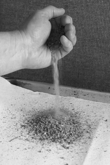
When the sand is dry as shown in Figure 2.7.1, it has an extremely high suction potential. Suction is like your potential to hit a home run. You have the necessary strength, hand-eye coordination and desire, but you lack a bat. You need something to help you hit the ball to score a home run. You can't think a home run, you can't hope a home run, what you need is a physical means to hit a home run. It's the same with soil suction and water. Water is the physical means for soil suction to apply tension stresses onto the soil skeleton, resulting in increased effective confining stress and increased soil strength. When a soil is completely dry with zero water content and zero degree of saturation, the soil suction is just sucking wind. No matter how high the suction's potential, it needs a little water to coat soil particles, form a membrane that acts like a balloon to develop tension stresses as the suction pulls in the water membrane “balloon.” As suction pulls in the water membrane, the membrane's tension stresses apply confining stress to the soil grains which increases strength of the soil and acts as apparent cohesion. When water is present to coat soil particles, soil suction can act to increase confining stresses in the soil structure, as shown in Figure 2.7.2. When water is absent, there are no increased confining stresses in the soil structure as shown in Figure 2.7.1. The formal name of this air–water interface membrane is the contractile skin (Fredlund and Morgenstern, 1977).
Figure 2.7.2 Added moisture to sand – now has apparent cohesion

As more and more water enters the voids of an unsaturated soil, air is eventually driven out of the sample. With no air voids, there is no soil suction or contractile skin, and the soil loses its apparent cohesion. You can see that effect, if you take a moist ball of sand like that shown in Figure 2.7.2 and drop it into a bucket of water. Once the ball of sand hits the water surface in the bucket, it loses all apparent cohesion and crumbles into a collection of sand grains.
Between a soil saturation of zero and a saturation of 100%, the soil increases in apparent cohesive strength until it is about 80 to 90% saturated, and then it rapidly loses strength until it is back to zero cohesive strength at approximately 100% saturation.
In their 1977 paper, Fredlund and Morgenstern (Fredlund and Morgenstern, 1977) formally describe unsaturated soil as a four-phase mixture of solid soil particles, water, air, and contractile skin. In that 1977 paper, the contractile skin is defined as an independent phase having properties different from air or water. Given that unsaturated soil is a four-phase mixture, how do we analyze unsaturated soils for stress changes, strength changes and volume changes?
2.7.3 Analysis of Unsaturated Soils
How do we analyze unsaturated soils and still stay true to the classical soil mechanics effective stress principle? For that matter, how do we stay true to laws of physics as we incorporate unsaturated soils into our soil mechanics theories? Remember, mechanics is a part of basic physics. Answers to these questions and many others have been developed by Del Fredlund during his studies under Professor Norbert R. Morgenstern, and during Dr. Fredlund's subsequent studies of unsaturated soils. I consider Dr. Fredlund's book (Fredlund and Rahardjo, 1993) to be the classic text on unsaturated soil mechanics and I recommend it for your library.
A very important concept in determining the shearing strength or compressibility of an unsaturated soil is finding the independent stress state variables. Do you know what independent stress state variables are? Ok, let's break it down. First, we need to figure out which variables are independent and which are dependent variables. Then we need to separate stress state variables from material properties and develop an equation of the form:
![]()
Notice that our idealized equations use stress state changes and appropriate material properties to calculate both unsaturated soil shear strength and volume changes. If we mix up our stress state variables with material properties, we will have difficulties solving different types of geotechnical problems. I'll try to explain how this works.
What if I decided to develop my own theory of effective stresses for unsaturated soils and use it to define shear strength? I might start out by stating that the shear strength of an unsaturated soil depends on its water content, porosity, soil suction, friction angle, cohesion, and confining stresses. My proposed theory is immediately in trouble. The water content is related to the porosity and to the soil suction and as such they are dependent on each other. If I try to use my proposed “theory,” I need to separate soil stresses and calculate stress changes, how do I do that when my theory has interdependence of soil properties with soil stresses? If I manage to come up with a way to calculate changes in unsaturated soil stresses, then I have to have appropriate soil material properties that define the shear strength changes in response to stress changes. If I mix parameters that define the soil stress state with soil material properties, I'll end up with a soil shear strength that is not independent of the tests I use to define the stresses and the strengths. Another way to say this is that the soil stresses will not be independent of the stress path used in testing soil properties. If you need further clarification of the requirement to separate soil stresses from soil material properties when characterizing unsaturated soils, please read Fredlund's text (Fredlund and Rahardjo, 1993) Chapter 3 carefully.
To calculate effective stresses in unsaturated soils, the soil suction needs to be defined in basic independent terms. We need to separate stress terms and define them as basic values of total stresses, water stresses, air stresses and contractile skin stresses. Any dependent terms in our equations of stress need to be eliminated to develop useful stress state parameters. That separation into independent and dependent stress and material variables helps us express soil shear strength and compressibility of unsaturated soils in their most basic terms. That is exactly what Dr. Fredlund did in his work. First he defined the three independent stress state variables of an unsaturated soil: (1) (σ – ua), (2) (ua – uw), and (3) (ua), where σ is the normal stress on a soil element in the x-, y- or z- directions, ua is the pore air pressure (when gauge pressure is used the pore air pressure is zero), and uw is the pore water pressure (in unsaturated soils the pore water pressure is negative, i.e., a suction). Then he proved that only two of these three independent stress state variables are required to solve the stress state for an unsaturated soil, and he selected the net normal stress (σ – ua) and the matric suction (ua – uw) for use in analyzing unsaturated soils.
I can hear some of you saying, “Alright, that's interesting. Let's get on with it. Give me the equation for the effective stress so I can start working.”
I'm sorry, but unsaturated soils are not a single equation type of problem. I told you there would be complications. Stop and think about this for a moment. The equations using net normal stress are effective stresses because the unsaturated soil has air in some voids and water in other voids. Only saturated soils require the subtraction of pore water pressure from total stress to calculate the effective stress. The complication of unsaturated soils is the independent requirement to consider the matric suction, (ua – uw). Matric suction is an additional confining stress that can increase the shear strength and stiffness of the soil if it increases (increased suction means it is becoming a larger negative number, i.e., its absolute value is larger) and reduce the shear strength and stiffness of the unsaturated soil if it decreases. As a result you have to consider two separate steps, first you have to determine how changes in matric suction affect the soil's confining pressure, and then you can consider how changes in normal and shearing stresses affect the soil's shear strength and compressibility. Let's consider shear strength of an unsaturated soil first.
Using the first two stress state variables, net normal stress and matric suction, as suggested by Fredlund, the shear strength of an unsaturated soil may be expressed as:
where
sff = the shear strength on the failure plane at failure
c′ = the intercept of the Mohr–Coulomb failure envelope at the vertical shear stress axis. This intercept is where both the net normal stress and the matric suction are equal to zero.
(σf – ua)f = net normal stress on the failure plane at failure
![]() ′ = angle of internal friction that generates shearing strength from changes in the net normal stress
′ = angle of internal friction that generates shearing strength from changes in the net normal stress
(ua – uw)f = matric suction on the failure plane at failure
ϕ b = angle of internal friction that generates shearing strength from changes in the matric suction on the failure plane at failure
The unsaturated soil shear strength Equation 2.7.1 transitions directly into the saturated soil shear strength equation as the soil's saturation increases. As soil saturation increases, the negative pore water pressure approaches the pore air pressure, at saturation the matric suction in the third term of the equation becomes zero and the pore air pressure in the second term of the equation becomes equal to the pore water pressure, thus converting the equation into that of a saturated soil.
How do you determine the terms included in the unsaturated soil's shear strength equation? You have to understand the concept of Mohr–Coulomb failure envelope extended to include both net normal stress and matric suction. In Fredlund and Rahardjo's text (Fredlund and Rahardjo, 1993), Chapter 9, pp. 228–235 there is a very good presentation of this material. Dr. Fredlund shows a three-dimensional plot that extend the standard Mohr–Coulomb failure envelope from two variables to three variables and defines c′, ![]() ′, and ϕb. I was tempted to repeat the Fredlund material here, but I just couldn't convince myself to do it. Why not? I have a confession to make to you. Every time I see a three-dimensional plot in a geotechnical text, I get a case of brain freeze. I just stop and stare at the figure. What does it all mean? I was afraid that you might have the same reaction looking at three-dimensional, three-variable plots. So I decided to use a different approach; an approach to dealing with three-dimensional plots that I have been using for years. Please allow me to digress for a moment.
′, and ϕb. I was tempted to repeat the Fredlund material here, but I just couldn't convince myself to do it. Why not? I have a confession to make to you. Every time I see a three-dimensional plot in a geotechnical text, I get a case of brain freeze. I just stop and stare at the figure. What does it all mean? I was afraid that you might have the same reaction looking at three-dimensional, three-variable plots. So I decided to use a different approach; an approach to dealing with three-dimensional plots that I have been using for years. Please allow me to digress for a moment.
Working example
I was talking with my friend Bob Meyers the other day and he told me and some other friends a story about back in the early 1990s he remembers coming into my office and seeing a Peacock diagram on the white board next to my desk. It was labeled “Peacock Diagram,” it was drawn as a three-dimensional plot, and there were three separate two-dimensional plots drawn next to it, each showing a section view of the Peacock diagram with a pair of variables on each two-dimensional plot. The Peacock diagram was first constructed in 1967 by William Peacock (Holtz and Kovacs, 1981), and it shows volume change, initial void ratio and effective confining stress of a sandy soil under drained triaxial shear testing. It illustrates the concept of dilation, compression, critical void ratio, and critical confining stress, and I kept it on my white board to remind me that even loose sands can dilate if their confining stresses are low enough to allow it. Anyhow, the point of the story is that I have always had to dissect three-dimensional plots into separate component two-dimensional plots to grasp a full understanding of the physical principles involved. Given that background, let me show you how the three independent variables of matric suction, net normal stress, and soil shear stress are related.
Consider Figure 2.7.3 which is a plot of effective normal stress versus effective shearing stress. Mohr–Coulomb Line No. 1 is a typical plot of a series of tests with the matric suction equal to zero. Zero matric suction implies that these tests are a series of saturated tests.
Figure 2.7.3 Mohr–Coulomb plot, net effective normal stress versus shearing stress
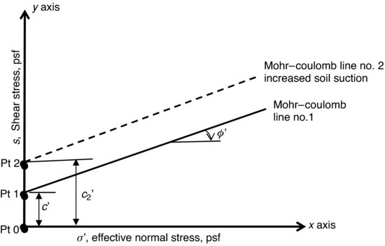
Point 0 is the point where the effective normal stress, the effective shearing stress and the matric suction are all equal to zero. The intercept of Mohr–Coulomb Line No. 1 with the vertical axis at point No. 1 is called the effective cohesion, c′. The effective cohesion is the minimum value of this soil's cohesion, where both the net normal stress and the matric suction are equal to zero.
Now let's dry the soil a bit to a saturation Sr value less than 100%. Some air has entered the soil pores and the pore water pressure has started to become negative, which means that the soil's matric suction has started to develop. When soil dries, its matric suction increases as the pore water pressure goes negative because matric suction equals (ua − uw) and when uw becomes negative ((ua – (−uw)) = (ua + uw). As a result of increased matric suction, the apparent confining normal stress on the soil mineral structure increases, resulting in increased soil shear strength (ΔS = Δσ tan ![]() ). Upon an increase in the soil's matric suction, the apparent cohesion of the soil moves from c′ to c2′ on the vertical axis because the effective normal stress, which is equal to the net normal stress, has not changed and is still equal to zero at the origin. The result of this increased cohesion intercept value is a shift in the Mohr–Coulomb line from Line No. 1 to Line No. 2 as shown in Figure 2.7.3. I have just illustrated three variables on a two-dimensional plot. Everything is done to illustrate the increase in shear strength due to soil matric suction, right? No not really. What we have done in Figure 2.7.3 is like looking at the front of a roof, see Figure 2.7.4. You can tell from looking at the front of a pitched roof that it is rising, but you need to look at the end of the roof, again in Figure 2.7.4, to see how steeply the roof is pitched, that is how flat or how steeply it is inclined.
). Upon an increase in the soil's matric suction, the apparent cohesion of the soil moves from c′ to c2′ on the vertical axis because the effective normal stress, which is equal to the net normal stress, has not changed and is still equal to zero at the origin. The result of this increased cohesion intercept value is a shift in the Mohr–Coulomb line from Line No. 1 to Line No. 2 as shown in Figure 2.7.3. I have just illustrated three variables on a two-dimensional plot. Everything is done to illustrate the increase in shear strength due to soil matric suction, right? No not really. What we have done in Figure 2.7.3 is like looking at the front of a roof, see Figure 2.7.4. You can tell from looking at the front of a pitched roof that it is rising, but you need to look at the end of the roof, again in Figure 2.7.4, to see how steeply the roof is pitched, that is how flat or how steeply it is inclined.
Figure 2.7.4 Frontal view of roof left, side view of roof right, you need to see the side view to measure the slope of the roof. With permission from John Wiley & Sons

When you are plotting independent parameters on the x- and z-axes, that is net normal stress on the x-axis and matric suction on the z-axis, you can plot them separately and add their affects on soil shear stress separately, as we did in Equation 2.7.1. So let's go ahead and look at the plot of matric suction on the z-axis versus soil shear stress on the y-axis, see Figure 2.7.5.
Figure 2.7.5 Matric suction versus shear stress
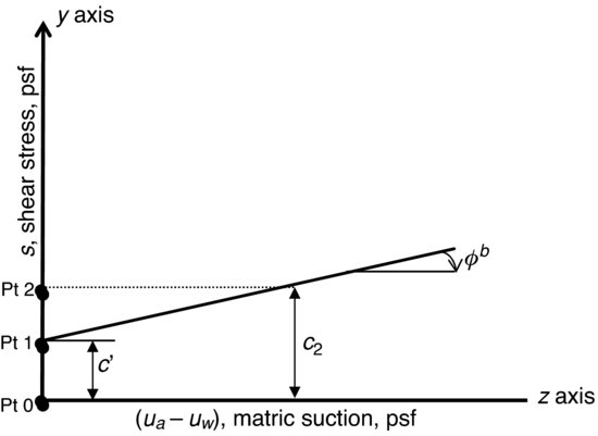
By looking at Figure 2.7.5 you can see the slope of the line of matric suction versus shear stress, like the slope on the roof in Figure 2.7.4. You can see from Figure 2.7.5 that the shear strength of the soil increases as the soil's matric suction increases. This is not a big discovery, because most of us know that drying a soil increases its shear strength, but now we have a way of illustrating and calculating how much the shear strength increases with a given decrease in water content (because the soil water characteristic curve gives you soil suction versus water content, see below). The slope of the matric suction versus shear strength line in Figure 2.7.5 is ϕb which is the term we need in Equation 2.7.1. Published data (Table 9.1 in Fredlund and Rahardjo, 1993) suggests that for a variety of soils the value of ϕb is less than the friction angle ![]() ′.
′.
I recommend that you study Fredlund and Rahardjo's text (Fredlund and Rahardjo, 1993) Chapter 9 for additional material on determination of shear strength of unsaturated soils.
Now when the laboratory technician calls you and asks if you want to run the direct shear test in an “as compacted” unsaturated state with a dry direct shear box, or do you want to run the direct shear test with the box saturated, what do you say? If you want lower bound shear strength values of c′ and ![]() ′, and you cannot provide assurance that the compacted soil will never become wetted, I'll bet you'll think of Figures 2.7.3 and 2.7.5 and ask the laboratory technician to make sure that the samples are thoroughly saturated before shearing each sample.
′, and you cannot provide assurance that the compacted soil will never become wetted, I'll bet you'll think of Figures 2.7.3 and 2.7.5 and ask the laboratory technician to make sure that the samples are thoroughly saturated before shearing each sample.
2.7.4 Expansive and Collapsible Soils
Two special cases of volume change of unsaturated soils are of particular interest to geotechnical engineers: (1) expansive soils and (2) collapsible soils. I'm going to discuss collapsible soils in depth in Section 3.2, so let me do an introduction to expansive soils here. First let me say that I don't particularly like the topic of expansive soils, and I'm not quite sure why. So what have I got against an inanimate object like a chunk of expansive soil? It might not be the soil at all, but rather the current rather heated debate in the geotechnical community about expansive soils that has me a bit down on the topic. I'm old fashioned, in case you didn't notice, and I really don't like to argue. I'm OK with discussing differing opinions, but I really don't like getting into an argument. You and I can disagree about any number of technical issues and still be friends. I have never been afraid to change my mind. If something new comes along to shed additional light on a geotechnical topic, I will gladly change my position if I'm proven to be wrong. It's not personal! It's professional. Several of my heroes, Einstein and Terzaghi among them, are famous for changing their minds. There is a famous case where Dr. Terzaghi is on the witness stand, and the opposing lawyer can't wait to point out that what Terzaghi just testified to was in conflict with his 1943 book, Theoretical Soil Mechanics. When confronted by the conflict between his testimony and his written opinion, Terzaghi said confidently, “Do you think that I haven't learned anything since 1943!”
The best way to visualize an expansive clay soil is to realize that this clay has very high soil suction when relatively dry. This soil suction generates high confining stresses that maintain the expansive clay in a compact state. As the expansive clay is wetted, the high confining stresses generated by this clay's soil suction reduces as the soil sucks in water. As the expansive clay's moisture content increases and its soil suction decreases, the expansive clay increases in volume, that is, it expands. If the same soil were dried, its soil suction would increase again, resulting in increasing confining stresses and decreasing volume, that is, it would shrink until it reached the shrinkage limit. Expansive clays are almost like living beings, they expand and contract as they take in and expel water in response to the environment. There are a couple of things to remember about the limitations of expansive clays. When expansive clays are wetted and prevented from increasing in volume they generate a swell pressure that is a function of the activity of the clay minerals present. At some depth in the ground the vertical effective stress equals the swell pressure of the soil and swelling does not occur at or below that depth. Free swell is when the clay is allowed to suck in as much water as it can and swell as much as it can without restraint. If you allow an expansive soil to freely swell, it does not generate measureable swell pressure. If after free swelling, you press the clay back down to its original volume you generate a vertical pressure that is usually less than the confined swell pressure. If you remold and highly compact an expansive clay on the dry side of optimum moisture content (i.e., modified Proctor compaction at minus 4% below optimum moisture content), you have just built a nice new expansive fill. If you moderately compact expansive clay at or above optimum moisture content (i.e., 90 to 95% of Standard Proctor compaction at 0 to 4% over optimum moisture content), you will initially have a weaker, more compressible fill, but if wetted it will not be a highly expansive fill. You may be able to lime treat an expansive clay to reduce its expansion potential, but be careful to make sure that it does not have significant amounts of sulfates (I personally try to keep the sulfates below 2000 ppm, but others quote the National Lime Association recommendation of 3000 ppm). Sulfates and lime grow a mineral called ettringite that causes chemical swell of the mixture during curing. There are construction techniques described in books published by the lime industry that describe how to temper lime-treated sulfate soils to help reduce chemical swelling. I personally prefer to avoid mixing lime with sulfates, but if you must, I suggest looking up the writings of Dr. Dallas N. Little for the National Lime Association. My advice is when in doubt, do your own testing of lime treatment on your project's soils, and maintain close quality control of the lime treatment process in the field.
2.7.5 Depth of Wetting
To estimate potential soil collapse or swell due to wetting, we need to test representative samples to determine the percentage collapse or percentage swell due to wetting, and we need to estimate or measure the depth of wetting. Determination of the depth of seasonal wetting is also important in evaluating the performance of landfill cover systems.
If you are not familiar with determining the depth of wetting, you might expect that it is no problem, no big deal, a slam dunk, and so on. I can hear you explaining how to solve the soil wetting problem:
Water flows onto the ground surface at a known rate of flow in inches per hour, gravity pulls the water down into the soil until the inflow stops, and then evaporation from the surface occurs until the liquid water is drawn out of the ground and the liquid phase changes into water vapor. If rainfall events are weeks or months apart like in the arid Southwest, and the evaporation rate is high, the ground will dry out completely. The depth of water penetration prior to reversal of inflow by evaporation is the depth of wetting … right? Then all you have to do is calculate the velocity of inflow by using Darcy's law, which says velocity of flow v = (k) (i). Where (k) is the soil permeability, and (i) is the inflow flux rate equal to ΔH / L. The hydraulic head loss ΔH in feet is the head loss while the water is flowing along the flow path of length L. I can get a lab to do a permeability test on the soil, and I'll use an upper bound limit value of gradient, i = 1. Using the inflow velocity, I can calculate how far the water penetrated … right?
Au contraire, not so fast, I told you geotechnical engineering could get complicated, and the depth of wetting issue is a prime example. Dr. John Nelson in a recent discussion (Nelson et al., 2011) in the ASCE Journal of Geotechnical and Geoenvironmental Engineering gave the following definitions of the depth of wetting:
1. Depth of Seasonal Moisture Fluctuation – This depth is that zone of soil within which water contents can change owing to climatic changes.
2. Depth of Wetting – This is the depth to which water contents can increase owing to external factors. Such factors could include capillary rise after elimination of evapotranspiration from the surface, infiltration from irrigation or precipitation, or water from off-site.
If I have interpreted Dr. Nelson's terms correctly, these definitions separate climate effects of wetting and drying from external factors which I interpret are somehow generated by the actions of man. I have noticed that the term depth of wetting is used in the literature for all kinds of soil wetting, whether it be by nature or affected by man. I agree with Dr. Nelson that it is prudent to pay attention to the sources of wetting, no matter what you call it. I wish we had consistent terms for geotechnical processes. It would surely make life easier. But alas we don’t.
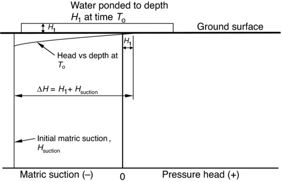
I'll just use the term depth of wetting and let you capture all of the potential sources of water involved in your problem. Ok, so what happens when water comes in contact with a relatively dry ground surface? Upon initial contact, the hydraulic gradient is very high. The hydraulic head ΔH = H1 – (−Hsuction) = H1 + Hs, that is change in hydraulic head is equal to the height of water above the ground surface (H1) plus the amount of soil suction acting at the soil surface, see Figure 2.7.6
Figure 2.7.6 Hydraulic head at ground surface of dry soil
Let's walk you through a rainfall event where the rain falls on an unsaturated soil surface. What is the infiltration rate of water into an unsaturated soil surface? As you might expect, the infiltration rate depends on the rainfall intensity and on soil properties. First consider a very light rain, where the rainfall intensity is less than the saturated hydraulic conductivity (a lower bound value of influx) of the soil. In this case all of the water that falls each second is sucked into the soil, and the infiltration rate equals the rainfall intensity. This is intuitively true. Using terminology of unsaturated soil mechanics, the infiltration rate is equal to the rainfall rate, since the minimum infiltration rate of the soil is equal to the saturated hydraulic conductivity (often called permeability) under a hydraulic gradient of one (Wilson, 1997). Whenever the rainfall intensity is less than the saturated hydraulic conductivity under a gradient of one (v = k * 1), all of the rainfall enters the ground surface immediately upon falling on the ground surface.
Next take the case that I discussed above, where there is a heavy rainfall and water ponds on the ground surface. Water ponds on the ground surface (assuming it doesn't run off to a drainage ditch) because the rainfall intensity is much greater than the soil's saturated hydraulic conductivity. This results in water piling up at the surface like a crowd trying to rush into an auditorium through too few doors. At the start of rainfall the hydraulic head at the ground surface is zero or a small positive number as water piles up while the suction just below the ground surface is very high. The soil suction for a very dry soil expressed as negative head may be as high as −33 500 feet (i.e., 100 000 kPa). Due to the extremely high hydraulic gradient between zero feet at the surface and −33 500 feet just below the ground surface, there is very rapid inflow of water into the ground. As time goes on and rainfall water penetrates deeper and deeper into the ground surface, the rate of inflow at the ground surface decreases because the hydraulic gradient decreases as the suction decreases due to wetting and as the distance between ground surface and wetting front increases.
After the rainfall stops, water starts to evaporate from the ground surface and flux in the saturated surface soil reverses from flow downward toward the soil suction to flow upward toward the atmosphere. During a given year rainfall water and snow melt soaks into the ground surface and evaporates back to the atmosphere. The depth of change of moisture content during annual seasonal precipitation and evaporation events is often referred to and used as the depth of wetting. This wetting is the “depth of seasonal moisture fluctuation ” that we were discussing above.
When the surface of the ground is artificially wetted by irrigation or ponding of water, saturated/unsaturated soil infiltration models are required to estimate the artificially induced additional depth of wetting.
During my work on the landfill projects, I learned about another method of increasing depth of wetting. We used riprap rock cover over our infiltration barriers on landfills to resist rainfall runoff erosion from severe storm events. The riprap rock acted like a mulch and retarded evaporation from the surface of the landfill cover. Retarding evaporation from the ground surface has the same effect as watering the ground surface: the depth of wetting into the ground increases.
2.7.6 The Soil Water Characteristic Curve
The soil water characteristic curve (SWCC) is the basic tool used by engineers to understand an unsaturated soil. The basic soil water characteristic curve is a plot of volumetric water content θw (Vwater/Vtotal) versus matric suction. Why do most groundwater engineers use volumetric water content rather than our normal geotechnical water content (Wwater/Wsolids)? I expect it is because they use porosity n (Vvoids/Vtotal) in many of their equations, and θw = n when the soil is 100% saturated.
Besides being a tool used to determine soil suction for a given water content value, the SWCC is used to model response of unsaturated soils to moisture changes. For example, permeability of unsaturated soils can be predicted by use of the soil water characteristic curve (Fredlund, Xing, and Huang, 1994).
In similar fashion to permeability, the SWCC is used in several computer models to estimate unsaturated soil material properties. The soil water characteristic curve for soil wetting is different than the curve for soil drying, see Figure 2.7.7 for typical wetting and drying SWCC curves for a sandy soil (from Fredlund and Rahardjo, 1993).
Figure 2.7.7 Soil water characteristic curves for wetting and drying, (Fredlund and Rahardjo, 1993)

2.7.7 Additional Study of Unsaturated Soils
The American Society of Civil Engineers has held several regional and national conferences on unsaturated soils and expansive soils. As a start, I recommend reading Geotechnical Special Publications numbers 39 and 68. Once you start to get some ideas about the topic, you will want to get a copy of Del Fredlund's book (Fredlund and Rahardjo, 1993) Soil Mechanics for Unsaturated Soils. If you want to look up papers in geotechnical publications about unsaturated soils and expansive clays, I suggest you start by searching for papers authored by Del Fredlund, Sandra Houston, Gordon McKeen, John Nelson, Warren Wray, Ward Wilson, and Robert Thompson. This is far from a complete list, but it will get you started.
References
ASCE (2003), A History of Progress – Selected US Papers in Geotechnical Engineering, American Society of Civil Engineers, Geotechnical Special Publication No. 118, vol.1, 1092 pages.
Fredlund, D.G. and Morgenstern, N.R. (1977) Stress state variables for unsaturated soils. American Society of Civil Engineers. Journal of the Geotechnical Engineering Division, GT5, 103, 447–466.
Fredlund, D.G. and Rahardjo, H. (1993) Soil Mechanics for Unsaturated Soils, John Wiley and Sons, 544 pages.
Fredlund, D.G., Xing, A., and Huang, S. (1994) Predicting the permeability function for unsaturated soils using the soil-water characteristic curve. Canadian Geotechnical Journal, 31(3), 533–546.
Holtz, R.D. and Kovacs, W.D. (1981) An Introduction to Geotechnical Engineering, 1st edn, Prentice-Hall, Inc., Englewood Cliffs, New Jersey, 733 pages.
Houston, S.L. (2011) Commentary: advancing the practice of unsaturated soil mechanics. Geo-Institute of the American Society of Civil Engineers. Geo-Strata Magazine, Issue No. 1, Vol. 15, January/February 2011, pp. 16–17.
Nelson, J.D., Chao, K.-C. and Overton, D.D. (2011) Discussion of “Method for evaluation of depth of wetting in residential areas” by Walsh, Colby, Houston and Houston, ASCE, Journal of Geotechnical and Geoenvironmental Engineering, 137, 293–296.
Terzaghi, C. (1925) Principles of soil mechanics, I–VIII. A History of Progress – Selected US Papers in Geotechnical Engineering, American Society of Civil Engineers, Geotechnical Special Publication No. 118, vol.1, edited by W. Allen Marr, pp. 2–38. Original articles in Engineering News Record 1925 Volumes 19, 20, 21, 22, 23, 25, 26 and 27, reprinted by the American Society of Civil Engineers.
Wilson, G.W. (1997) Surface Flux Boundary Modeling for Unsaturated Soils. American Society of Civil Engineers, Geotechnical Special Publication No. 68, pp. 38–67.