3.6
Laterally Loaded Piles and Shafts
3.6.1 Introduction of Laterally Loaded Piles and Shafts
In the 1950s and 1960s laterally loaded piles were analyzed primarily by three methods. The first method specified the allowable lateral loading on vertical piles or poles. These allowable lateral loadings were based on local load test experience. For example, a 12-inch diameter timber pile driven into sand or medium clay had an allowable lateral loading of 1500 pounds per pile; if soft clay was present the allowable lateral force was often limited to 1000 pounds per pile or less. To resist a 15 000 pound lateral loading by vertical piles driven into medium stiff clay, you needed 10 piles.
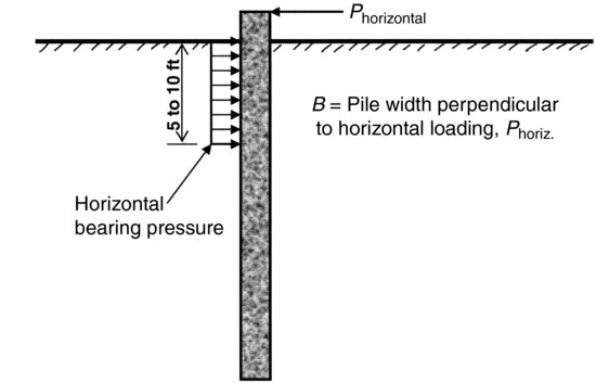
The second method was based on the assumption that lateral loading on piles was similar to vertical loading on spread footings. The upper 5 to 10 feet of the pile was assumed to resist lateral forces (some codes allowed up to 15 feet of pile), and so the area resisting lateral forces was assumed to be equal to the width of the pile times 5 or 10 feet, see Figure 3.6.1. Building codes gave values of allowable lateral bearing pressure or allowable lateral loading per foot of pile for soils described as loose, dense, soft, or hard. The 2000 International Building Code gave allowable lateral bearing pressures for isolated poles supporting buildings as 400 pounds per square foot for sandy gravel, 300 pounds per square foot for silty sand, and 200 pounds per square foot for silty clay. All you had to do to check the design of a pile or pole foundation for lateral loading was to divide the lateral pile force by the resisting pile area and compare the resulting stress to the allowable lateral pile pressure based on your assumed soil type. For years I thought that these building-code allowable lateral bearing pressure values were intended for spread footings only. It was after a structural engineer pointed out the paragraph on isolated flagpoles, signs, and pole-supported buildings that I learned that these values were actually being used for design of laterally loaded piles.
Figure 3.6.1 Laterally loaded pile with horizontal bearing pressure
Notice that I used the words “assume or assumption” several times in the above description of the second lateral pile analysis method. Bridge engineers who design piles to resist lateral loadings on a regular basis didn't particularly like either of the building-code-specified allowable lateral force or the allowable lateral bearing pressure concepts. Unlike building pile foundations that are in or adjacent to heated spaces, bridge piles are exposed to freeze–thaw conditions so bridge designers concluded that the upper 3 to 4 feet of their piles would not develop reliable lateral resistance. Bridge piles are often subjected to erosion from streams and rivers which remove near-surface soils, exposing the upper portion of these piles and reducing lateral pile resistance. Since available 10- to 12-inch diameter bridge piles did not have large diameters, bridge engineers in the 1950s and 1960s assumed that their piles did not have any bending resistance. To resist lateral loadings bridge engineers used battered pile, that is they used piles installed on an incline to vertical as shown in Figure 3.6.2.
Figure 3.6.2 Laterally loaded battered pile
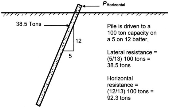
Notice that the battered pile's lateral resistance is calculated by using vector analysis from statics. The ratio of pile forces is taken as equal to the ratio of pile dimensions, as shown in Figure 3.6.2 for a 5 on 12 battered pile.
Geotechnical engineers and structural engineers in the 1960s were not satisfied with the use of allowable lateral pile force, allowable lateral pile bearing pressure and battered pile methods to resist lateral forces. Using earth pressure theories developed by Terzaghi, Wayne C. Teng of Teng and Associates in Chicago wrote a geotechnical text in the early 1960s (Teng, 1962) that used soil mechanics to analyze laterally loaded piles. Teng's work was with sheet piles walls that were used for lake-front construction and retaining of deep building foundation excavations. The simplified lateral earth pressure approach used by Teng to design laterally loaded sheet piles is shown in Figure 3.6.3. This method assumed that the pile was a rigid structure and that active and passive pressures are present on the loaded and unloaded sides of the pile.
Figure 3.6.3 Lateral loaded pile with active and passive soil pressures

Active earth pressure develops at relatively small lateral pile deflections and passive earth pressure develops at relatively large lateral pile deflections, so the lateral pressures shown on both sides of the pile in Figure 3.6.3 couldn't act at the same time at the same point on the laterally loaded pile. Besides, all piles are not rigid, so lateral bending of the laterally loaded pile would also modify the earth pressures generated on opposite sides of the laterally loaded pile. Teng's methods were widely distributed by reproduction in the United States Steel Sheet Pile Design Manuals (USS, 1969 and 1975) and in the US Navy's NAVFAC manuals. Teng's methods with some modifications are still used by present-day designers and are included in several lateral pile design computer codes.
The main problem with all of the methods discussed above is the lack of strain compatibility between the laterally loaded pile and the soil. This is where structural engineers come into the laterally loaded pile analysis history. A famous structural mechanics engineer named Stephen P. Timoshenko (1878–1972) (I recommend you look up Timoshenko's book on advanced strength of materials, it is the second volume of a two volume set (Timoshenko, 1956)) presented the equations for deflection, shear and bending moment of a beam on elastic (i.e., soil) foundation. Up until 1930, you would have had to read German or be a German engineer to study the works of Winkler (1867) or Zimmermann (1888). Timoshenko used a term he called the modulus of the foundation which denotes the foundation reaction that we now call the modulus of subgrade reaction. Timoshenko's modulus of subgrade reaction is the foundation reaction per unit length of the beam when the beam deflection is equal to one unit. Timoshenko's beam was a line, and its subgrade reactions were one-dimensional springs. Reviewing Timoshenko's book, he emphasized that the springs beneath his beam on an elastic foundation were capable of exerting both upward and downward forces. In other words, Timoshenko's subgrade could exert tension stresses on the beam, which is not likely with real-world soils. The beam's subgrade reactions are sometimes referred to as Winkler springs (Winkler, 1867). Since Timoshenko's beam was one-dimensional and his subgrade material was linearly elastic, the modulus of subgrade reaction used in his equations was a series of linear springs and his subgrade modulus k has units of pounds per inch length per inch deflection. Given the length of Timoshenko's beam is along the x-axis, and vertical beam deflection is along the y-axis, and the axis of bending is about the z-axis, Timoshenko's equation of a beam on elastic foundation is:
(3.6.1) ![]()
Turning Timoshenko's beam on an elastic foundation up into a vertical orientation several engineers, notably Reese and Matlock (Matlock and Reese, 1960), in the middle to late 1950s solved the equations for laterally loaded pile foundations. The main advantages of these numerical solutions were beam–soil deflection compatibility and the development of non-linear soil springs by use of p–y curves. We know that soil materials are not elastic, so the development of non-elastic stress–deflection relationships was a big advancement in modeling lateral deflection of piles in real soils. The main problem with these laterally loaded pile numerical solutions was timing. They were developed before the personal computer was invented. To use the Reese and Matlock method, you had to have access to a mainframe computer or use cumbersome graphs. Thanks to Federal Highway Administration support, the program COM624 was developed for use on mainframe and early personal computers, and not soon after a commercial version called L-Pile was developed as a PC application and put on the market in 1986. From the time I got my first IBM XT personal computer to the present day, I have used COM624 and then the successor versions of the L-Pile program to analyze laterally loaded piles and drilled shafts.
But what if you don't want to perform a computer analysis or if you want to check the L-Pile program by a hand calculation method, are you out of luck? No you are not out of luck; you have an alternate method available for hand calculation of laterally loaded piles. The hand calculation method that I use is Broms’ method (Broms, 1965). Broms’ method is discussed in the FHWA 2006 pile manual (Hannigan et al., 2006). The New York State Department of Transportation has developed a step by step procedure for the Broms method that is available on their website. The FHWA also has a free download of their manual FHWA-HI-97-013 (Hannigan et al., 1998) that includes the Broms method with all charts, tables and figures required to use this method. A few things to consider when using the Broms method:
1. Broms’ method is a hand calculation method for analyzing single vertical laterally loaded piles using charts and graphs to determine applicable parameters.
2. You can calculate the pile head deflection and loading, but you cannot calculate pile deflections at any other point along the pile. If pile deflection criteria are project critical, another method should be used.
3. Broms’ method ignores axial pile loading.
4. Broms’ method calculates the maximum soil resistance to lateral loading.
5. Broms’ method calculates the pile's maximum bending moment induced by lateral loading.
6. Broms’ method considers both free- and fixed-head piles. Free head means that the top of the pile is completely free to rotate during lateral loading. Fixed head means that the pile's top remains vertical, and that a bending moment is generated by the pile cap that restrains the pile head from rotating during lateral loading.
7. Broms’ assumes only one soil type at a time; either the soil is all cohesive or all cohesionless. Layered soils are not considered.
8. FHWA-HI-97-013 indicates that Broms’ method over-estimates the lateral load resistance for long, fixed-head piles in sands.
3.6.2 L-Pile Program Use – A Few Pointers
When asked by my young geotechnical engineers if there is any bit of general advice I can give them about the L-Pile program, I always say, “Remember that L-Pile was developed by structural engineers, so it is a structural engineering program with all of the conventions that go along with beam analyses.” Nearly every time I give this advice, I get the same response … a blank stare. What I consistently forget is that geotechnical engineers these days don't start out as structural engineers. Ralph Peck started as a structural engineer; I started as a structural engineer, and my friend Bob Meyers started as a structural engineer. Ralph has passed away, I am 65 years old, and my friend Bob is 57 or 58 years old (sorry Bob, I forgot). The point I'm making is that nearly every geotechnical engineer under 55 years of age has specialized from the beginning of their career in geotechnical or geological engineering. If I'm about to tell you some things that you already know well, consider this a refresher and please humor me.
The model of a vertical beam-pile in structural engineering is a one-dimensional line. It has no width or diameter like a real pile. All loading on the beam is a point load, a concentrated moment, a line load, or a variation on a triangular loading. All loadings are one-dimensional. The line loading has only length; it has no width, so it has units of pounds per lineal foot along the length of the beam, not pounds per square foot. If the model beam-pile has a free head, it can have a shear, but not a moment, at the head because it is free to rotate. If the beam-pile has a fixed head, it can have both a shear and a moment at the head because it is restrained against rotation. At every point of zero shear along the beam-pile, a maximum or minimum value of bending moment occurs. The equivalent point of fixity of a beam-column is not the point where the pile lateral deflection becomes zero, nor is it the point where the pile rotation is zero. The equivalent point of fixity is the point along the length of the pile where a fixed cantilevered pile would have the same deflection at the pile top when analyzed by the structural (above grade analysis) analysis program as the deflection computed by the (below grade) L-Pile program. This means that both computer programs (the structural engineer's bridge program and the geotechnical engineer's L-Pile program) have considered compatible stiffness when calculating lateral deflection of the top of pile. OK, I've adequately vented on structural versus geotechnical issues.
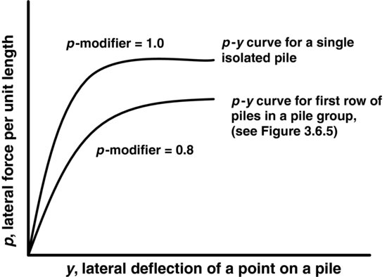
The L-Pile program is intended for analysis of a single pile or drilled shaft that is far removed from other piles, that is, no lateral pile interaction is assumed in the analysis. Lateral pile interaction factors are given in FHWA guidance documents, but they are considered by many engineers to be overly conservative. To include the pile interaction affect in an L-Pile analysis, the simplest technique is to use the “p–y modifiers.” For example, if the resisting soil in front of a laterally loaded pile is stressed by other piles in the group, the FHWA might suggest using a group reduction factor of 0.8 for this pile, I reduce the lateral soil resistance by using a p-modifier of 0.8. By use of a p-modifier in the L-Pile program, we reduce the reaction generated by pile deflection y as shown in Figure 3.6.4.
Figure 3.6.4 Pile-soil-pile group interaction, p-modifier
If you have a group of piles to analyze, you can roughly estimate group effects using the L-Pile program by analyzing individual piles using group reduction factors, but I don't recommend it. If you can afford the investment, I recommend you use the GROUP program, which was developed by the same engineers who wrote L-Pile. A word of caution, please read the GROUP manual carefully. There are several pile group interactions to consider. Geometry and stiffness of piles (lateral and vertical stiffness) making up a pile group affect the distribution of lateral and vertical loading in individual piles, the GROUP program considers these stiffness effects. You might be fooled to believe that the result of the GROUP program considers all of the factors required to provide specific “real” group reduction factors. Oh, I wish that were the case.
The GROUP program does not consider pile-to-soil-to-pile interaction affects. That is, the program still doesn't help you with the soils that are stressed by more than one pile. The pile group designer has to evaluate what p-modifier terms to use to include these pile–soil–pile interaction effects, as shown in Figure 3.6.5. I know this is difficult, but pile group interactions are one of the most difficult topics in geotechnical engineering.
At this point you have some choices, you can use guidance on group shadowing affects in FHWA manuals, you can read the group analysis material in Poulos and Davis book (Poulos and Davis, 1980), or you can perform a huge full-scale pile group load test. If you decide to do the load test, please let me know, because I am interested in the results of such tests.
What references do I recommend? I know that some geotechnical engineers don't like Bowles’ books (Bowles, five editions, 1968–1996), but then he was a structural engineer and his material on beams on elastic foundations and laterally loaded piles are good background information. In addition to carefully reading of the L-Pile and GROUP manuals, I recommend that you purchase and study a copy of Poulos and Davis’ book (Poulos and Davis, 1980). If you start to look over Poulos and Davis’ pile analysis book you will notice that their pile group analyses are based on elasticity principles, and I expect you might comment that soils are not elastic. True enough! With all of the complexity and multiple levels of variables involved in pile group analyses, if you use group reduction factors developed from elasticity principles you will be better off than guessing or better off than using factors that are not specific to your pile group. Then again, if you are up for a full-scale pile group load test, I'm game!
3.6.3 L-Pile Soil Input Parameters
When deciding what soil parameters to use for input into L-Pile, remember that clayey soils are c only, sandy soils are ![]() only, and soils with both c−
only, and soils with both c−![]() parameters used to characterize the soil shear strength are called silts. I know, your c-
parameters used to characterize the soil shear strength are called silts. I know, your c-![]() soil is a clayey silt or a silty clay or a sandy silty clay, no matter, if you want L-Pile to consider both the c and the
soil is a clayey silt or a silty clay or a sandy silty clay, no matter, if you want L-Pile to consider both the c and the ![]() properties of your soil, you will have to call it a silt. It's not geotechnical reality, it's just a computer convention used in this program.
properties of your soil, you will have to call it a silt. It's not geotechnical reality, it's just a computer convention used in this program.
I work mostly with silty sandy soil in New Mexico, so I use the API sand option in the L-Pile program, and I use the L-Pile Technical Manual figure that shows modulus of subgrade reaction ks (pounds per cubic inch) versus relative density versus angle of internal friction ![]() ′ to select a suitable value of ks.
′ to select a suitable value of ks.
Now is as good a time as any to discuss the modulus of subgrade reaction, ks. First of all the units of ks are not pounds per cubic inch. Pounds per cubic inch are units for density or unit weight, not modulus! The units of ks are pounds per square inch per inch deflection. When the pile applies a lateral pressure to the soil it causes a lateral deflection, the pressure applied to the soil divided by the resulting deflection of the soil is modulus of subgrade reaction for use in L-Pile. OK, I'm a purist, but I think that use of the units pounds per cubic inch for ks is just short-hand laziness!
I have given several lectures over the years on what modulus of subgrade reaction is and is not. I normally start out by saying that ks = p/δ where p is the applied stress and δ is the displacement caused by application of p. I also say that ks is not a constant, because it varies with stress level and it also varies with the width b of the applied stress (where b can be the footing width, the pile diameter, etc.). Since ks varies with stress level, it varies with depth z for deep foundations. The variation of subgrade modulus with foundation width and depth has led to two alternate definitions of soil subgrade modulus. To account for footing width, another subgrade modulus Ks in some references and ks' in other references is defined as Ks = ks' = ks b, where Ks or ks' has units of pounds per square inch and b has units of inches. The third alternate modulus of subgrade reaction that takes both foundation width and depth into account is most commonly called nh because it is applied most frequently to horizontal loadings where the horizontal modulus kh is required. The equation for kshorizontal = kh = nh (z/b), where nh has units of pounds per square inch per inch deflection or (it hurts) pounds per cubic inch.
When it comes to describing soil moduli in general, and modulus of subgrade reaction in specific, I am a fan of a short paper written by Jean-Louis Briaud. Dr. Briaud's paper is called Introduction to Soil Moduli and I highly recommend it (Briaud, 2001). I got a copy of this paper on Dr. Briaud's web page at the Texas A&M University website. Dr. Briaud summarizes the modulus (i.e., coefficient) of subgrade reaction as follows:
… the coefficient of subgrade reaction is not a soil property and depends on the size of the loaded area. Therefore, if a coefficient of subgrade reaction k is derived from load tests on a footing or a pile of a certain dimension, the value of k cannot be used directly for other footing or pile sizes.
3.6.4 Lateral Pile/Shaft Group Reduction Factors
It seems as if every time I turn around, there is a new published set of recommended lateral pile/shaft group reduction factors expressed as p-modifiers (i.e., for use in the L-PILE and GROUP programs). Remember my discussion of complexity in Section 1.2, and the saying hanging on my office wall, “You have to see it to solve it.”
I expect that the reason we see so many changes in recommended lateral pile/shaft group reduction factors is that there are too many unidentified variables impacting the results of lateral pile/shaft group reduction factor determinations. Let's take a look at some of the lateral pile/shaft group reduction factor recommendations from AASHTO/FHWA publications and see if we can identify where the hidden variables might be lurking. As you will see, the guidance and testing of laterally loaded piles and shafts seems to blend together, with many references to the words “piles” and “shafts” being used interchangeably in the literature. This is not too much of a problem if all of the piles and shafts are installed by drilling. A point to keep in mind is that driven displacement piles densify granular soils between piles and drilled piles/shafts loosen granular soils between piles. Driven piles should have higher values of p-multipliers than drilled piles for the same pile group installed at the same site. Many reported pile group reduction recommendations seem to ignore this fact. I suggest reading NCHRP Report 461 (Brown et al., 2001) for an interesting report on a full-scale lateral group load test on driven and drilled piles at Taiwan High Speed Rail Authority near the city of Chaiyi, Taiwan.
Tables 3.6.1 and 3.6.2 illustrate lateral pile group reduction factors given in the 1996 AASHTO ASD Design Manual. Table 3.6.3 gives similar recommendations for laterally loaded pile groups group reduction factors (GRF) from the AASHTO LRFD manuals published in 2007 and 2010. Best I can tell the data presented in Tables 3.6.1, 3.6.2, and 3.6.3 was intended for use with drilled piles and shafts, and would be conservative if used for driven pile groups.
Table 3.6.1 Load perpendicular to line of piles, group reduction factors from 1996 AASHTO ASD design specification
Table 3.6.2 Load parallel to line of piles, GRF 1996 ASD design specification
Table 3.6.3 FHWA 2007/2010 group reduction factors for lateral loading
One of the first things I notice when comparing lateral pile group reduction factors from earlier AASHTO Bridge Design Specification manuals that use allowable stress design (ASD) with the 2007 and 2010 load and resistance factor design (LRFD) group reduction factors is the use of soil descriptions in earlier guides and the lack of soil descriptions in the newer design guides. I have always been a bit skeptical of geotechnical guidance that divided all soil types into clay versus sand, and I expected that the new LRFD guidance would have provided more specific soil descriptions when giving group reduction factors. I was surprised, they not only didn't give more soil information, they dropped reference to soil types altogether! Why do you think they eliminated soil descriptions when specifying lateral group reduction factors? My guess is that they were trying to reduce complexity. Like I said in Section 1.2 engineering practice is becoming more and more complex with passing time, and the latest research into pile/shaft group reduction factors is no exception. The entire AASHTO 2007 Design Guide is 3.5 inches thick. The 2010 Design Guide is two volumes and the second volume by itself is 3.5 inches thick. I believe the authors of AASHTO's 2010 Design Guide were thinking of their primary audience, which is bridge design engineers, not geotechnical or foundation engineers, when deciding what material to include in the new manual. If every design topic from aluminum to timber structural design were covered in increasing detail in each issue of AASHTO's manual, it would become a 20 volume encyclopedia of bridge design.
The next difference that I noticed when comparing older ASD guidance for lateral loading perpendicular to a line of piles/shafts is the minimum spacing to achieve a group reduction factor (GRF) of 1.0. As shown in Table 3.6.1, older ASD design guidance used a group reduction factor of 1.0 (that is no reduction) when piles were spaced more than 2.5B apart (center to center spacing equal to 2.5 diameters). Both the 2007 and the 2010 LRFD design guidance requires shaft spacing of 5.0B or more to get a group reduction factor of 1.0. The 2007 LRFD guidance reduced the GRF to 0.7 for shaft spacing of 3B (which I believe is excessive reduction) and the 2010 LRFD guidance adjusted the GRF to 0.8 for shaft spacing of 3B. It has been my understanding that the guidance of 2.5B spacing given in the 1996 AASHTO ASD pile design guidance for perpendicular loading to a line of shafts resulting in a GRF of 1.0 went back to the early 1950s and was based on bench scale testing of anchor blocks at Princeton University (Merkin, 1951).
I have always assumed that computer modeling was used to double the spacing requirement from 2.5B to 5.0B to achieve a GRF of 1.0, and I have been on the lookout for a publication or reference that would define the assumptions used in the model runs. In the 2010 AASHTO manual a reference is given for this GRF change from earlier GRF values and the reference is the 2006 FHWA Pile Manual (Hannigan et al., 2006). That got me thinking, so I looked up the GRF guidance in both the FHWA 2006 pile manual and the 2010 Drilled Shaft Manual. As I expected, they don't spare us the pain of complexity in these geotechnical-based references.
In the 2006 AASHTO Pile Manual (Hannigan et al., 2006) on page 9–153 in Table 9-19, the authors report group reduction factors for 10 cases, including laterally loaded pile groups in stiff clays, medium clays, clayey silt, loose sands, medium dense sand, and very dense sand. None of the 10 cases indicate whether the piles were driven displacement piles or drilled piles. Eight of the reported 10 cases are at pile spacings of 3B, while the remaining two cases are at 5B spacings. Five of the tests are full-scale field studies, four tests are in the centrifuge, and one of the tests is a scale model with cyclic loading. Knowing the problems with scale models at 1g testing, I would be somewhat suspicious of the scale-model test results. Group reduction factors reported in the 2006 AASHTO Pile Manual for the first row, second row, and third or higher rows (see Figure 3.6.5) do vary with soil type, as summarized in Table 3.6.4 below:
Figure 3.6.5 FHWA 2007/2010 guidelines for group reduction factors

Table 3.6.4 Pile group reduction factors from the 2006 AASHTO Pile Manual

It looks like the GRF recommendations for 5B pile spacing included in the 2010 AASHTO Design Manual is based on loose to medium dense sand tested by McVay et al., in 1995. It looks like the GRF recommendations for 3B spacing included in the AASHTO 2010 Design Manual are based on medium dense to very dense sand tested by McVay et al., in 1995 and by Brown et al., in 1988. I see enough variations in GRFs for 3B spacing in Table 3.6.4, that is, varying from 0.65 to 0.80 for the first row of piles that I would like to see many more tests to determine soil-specific group reduction factors.
What group reduction factors are recommended in the 2010 AASHTO Drilled Shaft Manual (Brown, Turner, and Castelli, 2010)? They say that it is important to consider group reduction factors when drilled shafts are spaced less than about six diameters apart in any direction. This seems like reasonable advice since older design guides recommended a GRF of 1.0 for shafts spaced five diameters apart in clays and eight diameters apart in sands.
Table 3.6.5 Shaft group reduction factors, p-multipliers for each row

The AASHTO 2010 Drilled Shaft Manual covers similar group reduction p-multipliers as discussed in the 2006 Driven Pile Manual, in fact they reference the same full-scale and centrifuge studies described in the pile manual. This might make the reader believe that there is no difference between driven piles and drilled shafts. But later in the text of the drilled shaft material, they explain that there is a difference in the impact on group reduction factors between soil types and pile/shaft installation techniques. Reduction factors recommended in the 2010 Drilled Shaft Manual are given above in Table 3.6.5.
Although it doesn't say specifically in the 2010 Drilled Shaft Manual, I believe the factors listed in Table 3.6.5 are for loadings parallel to the piles as shown in Figure 3.6.5. Notice that for spacings of three and five diameters, the reduction factors given in Table 3.6.5 are identical to those given in the AASHTO 2007 Design Manual for Piles, see Table 3.6.3.
I have always thought that the lateral group reduction factors included in Table 3.6.2 were conservative. I first recall seeing these values in the 1996 AASHTO Design Guide, and was confused why these factors were so much smaller (that is a much greater reduction of lateral resistance) than those included in Reese and O’Neill's Drilled Shaft Manual of 1988 (Reese and O’Neill, 1988). Upon review of my 1988 manual, the problem became clearer, or at least I began to understand the difference. In the 1988 FHWA Drilled Shaft Manual Reese and O’Neill recommended a minimum shaft spacing of 3B and a group reduction factor of 0.67 for 3B shaft center-to-center spacing for sands and clays. They recommended 6B spacing for both sands and clays to achieve a GRF of 1.0 and they allowed you to linearly interpolate between shaft spacings of 3B and 6B to find intermediate GRFs. But then I realized the big difference between the 1996 and the 1988 recommendations, in 1988 the given group reduction factors were for vertical loadings only. Group reduction factor research for drilled shafts was just beginning in the 1980s. Up until that time engineers generally assumed drilled shafts had large load capacities and that they would replace pile groups. Since single drilled shafts were replacing pile groups they were assumed to be widely spaced. Group reduction factor research was initially conducted for vertically loaded shaft groups, and not for laterally loaded shaft groups. The 1988 Drilled Shaft Manual does not include recommendations of group reduction factors for laterally loaded drilled shaft groups, which explains why the 1996 lateral GRF values seemed so restrictive to me, I'd never seen them before!
As shown in Table 3.6.3, a spacing of 5B with no regard to soil type gives a reduction factor of 1.0 for the first row of piles, 0.85 for the second row of piles, and 0.70 for the third row and all higher numbered rows, as illustrated in Figure 3.6.5. This change back to something closer to earlier recommendations makes me wonder if they have more data or a change of mind or both.
Thinking about the difference in installation techniques, it doesn't seem right that the 2010 AASHTO Design Guide gives the same GRF for drilled shafts as augercast piles, and it surely doesn't seem right that the GRF for driven displacement piles is the same that given for augered piles. If, as I mentioned earlier, you check the 2001 NCHRP Report 461, Static and Dynamic Lateral Loading of Pile Groups, you will see that they report higher group reduction factors (i.e., less reduction of lateral resistance) for driven displacement piles versus smaller GRFs for augered piles (i.e., more reduction of lateral resistance). This makes sense to me.
It doesn't seem right to neglect soil types when considering group reduction factors for lateral loading, and it doesn't seem right that densification of loose soils by installation of driven displacement piles is not considered in determining group reduction factors.
My suggestion to you the reader is to focus on specific driven pile and drilled shaft manuals and reports for guidance in selecting lateral group reduction factors, and use the AASHTO LRFD Design Manual as general guidance when applying the geotechnical LRFD design methods.
References
Bowles, J.E. (1996) Foundation Analysis and Design, 5th edn, McGraw Hill Inc., 1024 pages.
Briaud, J.-L. (2001) Introduction to Soil Moduli, Geotechnical News, vol. 19(2), June 2001, BiTech Publishers Ltd, Richmond, B.C., Canada, pp. 54–58.
Broms, B.B. (1965) Design of laterally loaded piles. Journal of the Soil Mechanics and Foundation Division, The American Society of Civil Engineers, 91(SM 3), pp. 79–99.
Brown, D.A., Reese, L.C., and O'Neill, M.W. (1987) Cyclic lateral loading of a large-scale pile group in sand. American Society of Civil Engineers. Journal of Geotechnical Engineering, 113(11), 1326--1343.
Brown, D.A., Morrison, C., and Reese, L.C. (1988) Lateral load behavior of pile group in sand. American Society of Civil Engineers. Journal of Geotechnical Engineering, 114(11), 1261–1276.
Brown, D.A., O’Neill, M.W., Hoit, M., McVay, M., El Naggar, M.H., Chakraborty, S. (2001) Static and Dynamic Lateral Loading of Pile Groups, NCHRP Report 461, National Academy Press, Washington, D.C., 59 pages and 6 Appendices.
Brown, D.A., Turner, J.P., and Castelli, R.J. (2010) Drilled Shafts: Construction Procedures and LRFD Design Methods, NHI Course No. 132014, FHWA NHI-10-016, Geotechnical Engineering Circular No. 10, 970 pages.
Hannigan, P.J., Goble, G.G., Likins, G.E., and Rausche, F. (2006) Design and Construction of Driven Pile Foundations – Volumes I and II, Report Number FHWA-NHI-05-042, U.S. Department of Transportation, Federal Highway Administration, 968 pages.
Hannigan, P.J, Goble, G.G., Thendean, G., Likins, G.E. and Rausche, F. (1998) Design and Construction of Driven Pile Foundations —- Volumes I and II, Report Number FHWA-HI-97-013, U.S. Department of Transportation, Federal Highway Administration, 828 pages.
Matlock, H. and Reese, L.C. (1960) Generalized solutions for laterally loaded piles. Journal of the Soil Mechanics and Foundation Division, The American Society of Civil Engineers, 86(SM 5), 63–91.
Merkin, T.A. (1951) Small-scale Model Tests of Dead-man Anchorages. Master's Thesis, Princeton University, May 18, 1951, number of pages unknown. Photographs and data from Merkin's work are included in Tschebotarioff, G. P., 1973, Foundations, Retaining and Earth Structures, 2nd edn, McGraw Hill Book Company, New York, pp. 538–539.
McVay, M., Casper, R., and Shang, T.-I. (1995) Lateral response of three-row groups in loose to dense sands at 3D and 5D pile spacing. American Society of Civil Engineers, Journal of Geotechnical Engineering, 121(5), 436–441.
Poulos, H.G. and Davis, E.H. (1980) Pile Foundation Analysis and Design, John Wiley and Sons, pages 397.
Reese, L.C. and O'Neill, M.W. (1988) Drilled Shafts: Construction Procedures and Design Methods'', Federal Highway Administration Publication No. FHWA-HI-88-042 and ADSC: The International Association of Foundation Drilling Publication No. ADSC-TL-4, 564 pages.
Rollins, K.M., Peterson, K.T., and Weaver, T.J. (1998) Lateral load behavior of full-scale pile group in clay. American Society of Civil Engineers, Journal of Geotechnical and Geoenvironmental Engineering, 124(6), 468–478.
Ruesta, P.F. and Townsend, F.C. (1997) Evaluation of laterally loaded pile group at Roosevelt Bridge. American Society of Civil Engineers. Journal of Geotechnical and Geoenvironmental Engineering, 123(12), 1153–1161.
Teng, W.C. (1962) Foundation Design, Civil Engineering and Engineering Mechanics Series (eds Newmark, N.M. and Hall, W.J.), Prentice-Hall International, Inc., 466 pages.
Timoshenko, S.P. (1956) Strength of Materials, Part II, Advanced Theory and Problems, 3rd edn, D. Van Nostrand Company, p. 572.
United States Steel Corporation (no author given) (1969 and 1975), Steel Sheet Piling Design Manual, printed by USS, 132 pages (1969) and 132 pages (1975).
Winkler, E. (1867) Die Lehre v. d. Elastizität u. Festigkeit, Prag, 182 pages.
Zimmermann, A. (1888) Die Berechnung des Eisenbahn-Oberbaues, Berlin, pages unknown.