4.3
Tieback Walls
4.3.1 Introduction to Tieback Walls
Abutments for the proposed bridge planned at the gorge site shown in Figure 4.2.11 are a good place to consider use of tieback walls and rock bolts with shotcrete facing. In fact, any retaining structure over 15 feet in height is a candidate for tiebacks. A retaining wall that uses tiebacks may be called an anchored wall, although use of the term “anchor” has a nautical flavor that seems to be fading in favor of tiebacks when construction moves inland from the ocean fronts to Midwestern United States highways. Personally I use the terms “tieback ” and “tieback anchor ” interchangeably as you will see below.
Why do we use tieback anchors? The primary purpose of tiebacks is to provide additional lateral support to a retaining structure because it is too tall to be cantilevered. Retaining walls with tiebacks are, as you might expect, highly statically indeterminate structures. We have to make many assumptions about the nature of the retained soil and the wall structure to design tieback walls.
I like to think of this wall design process as one of self-fulfilling predictions, or as the old saying goes, “It is a self-fulfilling prophecy.” What do I mean? The idea is that you pick the magnitude and location of a retaining wall's tieback loading, and the tieback loading develops where you selected if the relative stiffnesses of the component wall parts are designed properly. Take a look at Figure 4.3.1; in this figure I propose that you can analyze a sheet-pile wall with a single level of tiebacks in two alternate ways (there are more than two ways, but we're just using this as an example).
Figure 4.3.1 Are these loading cases self-fulfilling prophecies?
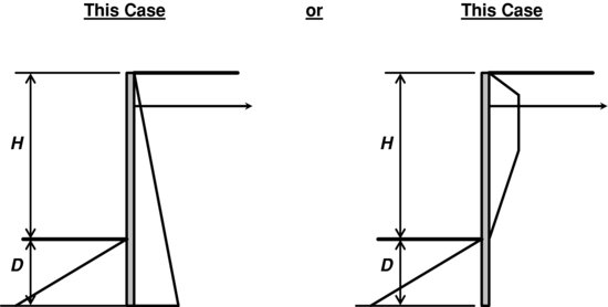
The method on the left in Figure 4.3.1 has an active earth pressure distribution on the back side of the sheet piling and a passive earth pressure distribution in front of the piling. This distribution of lateral earth pressures is identical to that proposed for analysis of a cantilevered sheet-pile wall. The tieback loading has added a lateral force near the top of the sheet piling, but it has not changed the earth pressure distribution. The method on the right in Figure 4.3.1 has an increased lateral earth pressure toward the top of the sheet piling with the same passive earth pressure acting below the toe of wall.
I've heard my students say many times, “Which case is the right answer? One of these cases has to be right and the other one is wrong, which one is it?”
The answer is that they are both correct. Which one you choose to use depends on your design assumptions and how the tieback is installed.
The wall illustrated on the left in Figure 4.3.1 has apparently deflected sufficiently for an active earth pressure distribution to develop. After the pile deflected and active earth pressure developed, the tieback anchor was installed without prestressing. All the tieback anchor does in this case is provide a greater factor of safety and prevent the top of wall from moving much further.
The wall illustrated on the right in Figure 4.3.1 has not deflected sufficiently for an active earth pressure distribution to develop. The tieback in this case was installed prior to excavating in front of the sheet pile thus preventing the pile top from moving. Alternately, the tieback could have been stressed to develop compression stresses in the retained soil. By prestressing the tieback anchor, the top of the sheet pile wall can be prevented from moving, or it may actually be pulled into the soil mass. The required depth of pile embedment D, the bending stresses generated in the sheet piling, and the tieback anchor force can be significantly different in the two cases illustrated in Figure 4.3.1. You can control the distribution of loading and the lateral stresses by changing the loading applied to the tieback anchor. Within limits of geometry and soil strength, it is a self-fulfilling prophecy!
4.3.2 Retaining Structures with One Row of Tiebacks
You have the choice to analyze a wall with a single row of tiebacks by either method illustrated in Figure 4.3.1. For years I used the method illustrated on the left, which I will call Case 1. To support the top of my sheet-pile walls, I used anchor rods tied to deadmen. Today with the variety of drilled and driven anchors that are prestressed, post-tensioned and proof-loaded, I frequently use the case shown on the right side of Figure 4.3.1, which I will call Case 2. The decision on which method to use depends on your understanding and control of lateral deflections of the sheet-pile wall.
4.3.2.1 Case 1
First I will explain how to analyze a sheet-pile or soldier-pile wall for Case 1, assuming that active earth pressures are generated as shown in the case on the left in Figure 4.3.1. To further illustrate this analysis method, please refer to Figure 4.3.2.
Figure 4.3.2 Analysis of one row of tiebacks – Case 1

When we start analysis of the tieback sheet-pile wall illustrated in Figure 4.3.2, we don't know what values to assign to the tieback force P and to the pile embedment length D. To isolate these two variables, take summation of moments about point O, which is the connection point of the tieback anchor to the sheet pile. Since the lever arm distance of force P about point O is zero length, the moment of force P about O is zero and we have eliminated the force P from our first calculation. Now you have one variable left in your summation of moments about point O, and that variable is D:

This looks a bit messy doesn't it? You don't know the value of D, and the variable D is included in five terms in Equation 4.3.1. I start by assuming D is ½ H, if the resulting summation of moments is a large positive number, I reduce D and resolve Equation 4.3.1. If the result of my first estimate of D gives a summation of moments that is a large (absolute value) negative number, I increase D and resolve Equation 4.3.1. An alternate to this trial and error method is to set up a spreadsheet with D varying from 1 foot to H feet, and select the value of D that gives a value of Equation 4.3.1 closest to zero. I often use the spreadsheet method of solving for D these days because I have to include calculation of D in my calculation data package.
OK, now you have a theoretical value of the sheet-pile embedment depth D, and can calculate a value for the passive resistance Pp. Next you need to calculate a theoretical value of the tieback anchor force P. Force P is on a per foot of wall basis. To determine P, I take summation of forces in the horizontal direction:
(4.3.2) ![]()
Now we have a theoretical embedment and a theoretical tieback-anchor force (per foot of wall), and all we need to do is determine the required design values of D and P. We also need to check bending stresses in the sheet piling or select a sheet piling size. For the design value of D, I increase D by 30% as recommended in the USS Manual (US Steel Manual, 1969 and 1975), so design embedment equals 1.3D. For the required design tieback-anchor force, equal to P times anchor spacing S, the required factor of safety depends on the level of anchor testing planned for the project. If all of the anchors are proof-tested to 125% of design tieback-anchor force, I use a design tieback-anchor force of P, which is equal to the theoretical anchor force. If no anchors are proof-tested, and a few representative anchors are tested to failure, I use a design tieback anchor force equal to 50% of the failure loading, 0.5PFailure. Even if all tieback anchors are proof-tested to 125% of design loading (some specifications require 130%), I always recommend testing a few representative tieback anchors to pullout failure or a minimum of 2P, 200% of design loading. The actual numbers of failure tests depends on site variability and the size and importance of the project.
Finally we need to size the sheet piling or check bending stresses in the sheet piling suggested by the project contractor. In the old days when United States Steel and Bethlehem Steel were still in business, we always calculated the required sheet-pile section modulus and selected the next larger size of sheet piles from the steel design manual. Today, we often have to use the sheet piling that the contractor has available or the size of sheet piling that he can reasonably obtain. In this case, we don't calculate the required section modulus, we have to use the section modulus provided by the available piling. Most sheet piles these days have yield strengths of 50 kips per square inch. Don't take my word for it; always check the provided steel members’ yield strength! To check bending stresses in sheet piling provided, you have to find the point of zero shear in the piling.
Start at the top of pile and working toward the bottom, take summation of forces in the horizontal direction until the value equals zero (don't stop at the location of the tieback). At the point on the piling where the shear equals zero, calculate the bending moment of the forces above the point of zero shear. Using an allowable bending stress of 0.6Fyield, divide the bending moment in kip inches by the allowable bending stress in kips per square inch to find the required section modulus Sx–x. If you have a given pile with section modulus Sx–x, divide the maximum bending moment in kip inches by the section modulus Sx–x in inches cubed and find the bending stress in kips per square inch. Finally you compare the calculated maximum bending stress to the allowable bending stress of 0.6Fyield (30 ksi for commonly found 50 ksi yield strength steel).
4.3.2.2 Case 2
Prior to my return to highway project work in the late 1990s, I used the triangular active lateral earth pressure distribution for walls with one row of tiebacks, and I used the Terzaghi and Peck lateral earth pressure distributions (Terzaghi and Peck, 1967) for walls with multiple levels of tiebacks. I might add that Ralph Peck gave all of the credit to Karl Terzaghi for these lateral earth pressure distributions, but in modern day usage, authors of multiple texts and manuals give Ralph credit also, thus the name “Terzaghi and Peck method.”
I first became aware of the Case 2 lateral earth pressure distribution while reading an FHWA manual on ground anchors and anchored systems in late 1999 (Sabatini, Pass, and Bachus, 1999). This is still a good reference and I recommend that you download it from the FHWA website. This manual is currently called “Geotechnical Engineering Circular No. 4, Ground Anchors and Anchored Systems, FHWA-IF-99-015, June 1999.”
To analyze a sheet-pile or soldier-pile wall for Case 2, we assume that lateral earth pressures generated are as shown on the right side of Figure 4.3.1. I say “assume” to describe these earth pressures because they are not based on earth pressure theories such as Rankine's or Coulomb's theories, rather the earth pressure distribution shown in Figure 4.3.3 below comes from field testing of anchored walls. The basic method used to develop earth pressure distributions from field testing involves measuring tieback anchor loads and dividing them by a tributary area of the wall supported by each anchor.
Figure 4.3.3 Analysis of one row of tiebacks – Case 2

The analysis of Case 2 starts similarly to Case 1 because we don't know what values to assign to the tieback force P and we don't know the pile embedment length D. To isolate these two variables for Case 2 take summation of moments about point O. In the equation of moments you have one unknown variable which is the depth of embedment D, see Equation 4.3.3 below:
When solving Equation 4.3.3, you can start at 1 foot embedment and go up to a depth equal to H in a spreadsheet, then pick the value of D that gives you a summation of moments close to if not equal to zero. After you determine D, calculate a value of PTieback (again on a per foot of wall basis) by taking summation of forces in the horizontal direction equal to zero. After you have theoretical values of D and PTieback required for static equilibrium, increase the value of D by 30% and calculate the final embedment 1.3D. Using factors of safety on the tieback anchor force that are based on your anchor-testing program (as described above or in FHWA-IF-99-015), calculate the design tieback anchor force. After you have the pile embedment and tieback force, you can calculate the point of zero shear and determine the maximum bending moment for sizing sheet piling or checking piling bending stresses.
Now you are done with the tieback wall design, right? No way; there are many more details to consider. You have to design the anchor embedment to secure your tieback. You have to make sure that the tieback length is adequate to allow development of the anchor force beyond the zone of active shear wedge development. You have to design and detail the anchor connection system to the face of your sheet pile wall or to your soldier piles. If you use waler beams, you have to design them.
There are 10 potential failure modes for tieback-wall systems listed in the FHWA-IF-99-015 manual. All 10 of these failure modes need to be considered when analyzing and designing a stable retaining wall-tieback system. These failure modes include:
1. Tension failure of the tieback tendon (i.e., the tieback rod or cable snaps!)
2. Tieback's anchor pulls out of the soil because adequate bond and passive resistance of the anchor to the soil was not generated.
3. The grouted anchor rod pulls out of the anchor's grout due to a lack of rod to grout bond strength.
4. Failure of sheet-pile or soldier-pile members in bending or excessive deflection due to high bending stresses.
5. Kick out of the toe of wall due to insufficient passive resistance of soil in front of the toe. This can be caused by installing piles in very soft, wet clay, then rapidly backfilling behind the wall causing settlement and excessive lateral shearing stresses due to excess pore water pressure, resulting in very low undrained shear strength of embedment soils. Excessive consolidation settlements in this case can also shear off the tieback anchor connection to the sheet pile wall.
6. Excessive leaning of the top of cantilevered pile prior to installing the first tiebacks. This is a construction sequencing problem that requires evaluation of the maximum allowable height of the cantilevered wall prior to installing tiebacks.
7. Failure of the piling in vertical bearing. This occurs when battered anchors and downward pile–soil friction generated during development of the active wedge apply an excess vertical loading on the piles causing them to punch into soils below the tip of pile.
8. Overturning failure of the sheet-pile wall plus anchor system acting as a whole. This type of failure is considered a global stability analysis problem, where the entire wall with tiebacks acts as a unit that slides and rotates outward.
9. Sliding block failure where the sheet piles and anchors act as a unit block. Again this type of failure is a global stability analysis problem that requires analysis of the entire wall system as a unit.
10. Rotational slide failure where a minimum factor of safety failure surface passes outside of and beneath the entire tieback-wall system. This tenth type of wall failure can affect any retaining wall system, because it is a deep-seated landslide problem that takes your retaining wall along for the ride.
4.3.3 Retaining Structures with Multiple Rows of Tiebacks
Analysis of retaining walls with multiple rows of tiebacks should never be done with a triangular active earth pressure acting on the wall. It has been known almost since the beginning of geotechnical engineering that the lateral earth pressure generated behind sheet-pile and soldier-pile walls with multiple rows of tieback anchors is a rectangular or trapezoidal stress distribution. You can find details of these stress distributions in early works by Terzaghi and Peck (Terzaghi and Peck, 1967), and in Tschebotarioff's textbook (Tschebotarioff, 1973). Discussions of retaining walls with multiple rows of tiebacks are also included in the US Army Corps of Engineers and NAVFAC publications that are available for free on the internet.
I recommend that you study and review FHWA-IF-99-015 (Sabatini, Pass, and Bachus, 1999) to help you decide which lateral earth pressure distributions to use for retaining walls with multiple rows of anchors. This reference gives updated stress distribution recommendations for sands and soft to medium clays, including the Henkel method, and it also compares and contrasts six alternate methods of determining lateral stresses in stiff to hard clays.
References
Sabatini, P.J., Pass, D.G., and Bachus, R.C. (1999) Geotechnical Engineering Circular No. 4, Ground Anchors and Anchored Systems, Report No. FHWA-IF-99-015, Office of Bridge Technology Federal Highway Administration, 281 pages.
Terzaghi, K. and Peck, R.G. (1967) Soil Mechanics in Engineering Practice, John Wiley & Sons, Inc., New York, N.Y., 729 pages.
Tschebotarioff, G.P. (1973) Foundations, Retaining and Earth Structures, 2nd edn, McGraw Hill Book Company, New York, 704 pages.
United States Steel Corporation (1969 and 1975) Steel Sheet Piling Design Manual, 133 pages both editions. Much of the material included in these USS manuals can be found in Wayne C. Teng's book, 1962, Foundation Design, Chapter 12, Prentice Hall, Englewood Cliffs, New Jersey, pp. 347–386.