Chapter 8. Automatic Garden-Irrigation System
In Chapter 6 you combined what you had learned about Arduino into a project, the Arduino Networked Lamp. Part of the fun was to combine some of the simple exercises into a practical project. You also learned about the Processing language and how to use it to create a proxy on your computer to do things that would be difficult or impossible with your Arduino.
In this chapter you will again combine simple examples with some new ideas to make a practical project. Along the way you’ll learn more about electronics, communication, and programming, and we’ll give some attention to construction techniques.
The goal of this project is to automatically turn the water on and off at the right time each day, except if it’s raining.
Note
If you don’t have a garden, you can still have some fun with this project. If you just have a small houseplant you want to water, try building this with only one valve. If you need to dispense a tasty beverage of your choice at 5 p.m. each day, consider using a food-grade pump instead of the water valve. For example, Adafruit sells a Peristaltic Liquid Pump with Silicone Tubing.As a professor, I teach many students to build things. Along the way it occurred to me that students sometimes think that I instantly know exactly how to build a project. In fact, designing a project is an extremely iterative process.
—Michael
To create a project, start with an idea, and rough out little pieces of it; as you go, this sometimes requires making changes to the initial idea. We often have to take a detour to learn how a new electronic part works, or to figure out a programming concept we’ve not encountered before, or remind ourselves how to use a feature of Arduino we’ve not used in a long time or is new to us. Sometimes we have to turn to our textbooks, the Internet, or ask someone for advice. We review many examples, tutorials, and projects that contain bits related to what we are doing. We take bits and pieces from different places and combine them, perhaps very roughly at first, like Frankenstein’s monster, to see how things will work together.
As the project progresses from concept to rough design to testing parts of the hardware and software, we keep having to go back and make changes in something we did earlier, so that everything will work together properly. We don’t know a single engineer who starts with a blank piece of paper, designs a whole project from start to finish, which then works exactly as planned, without ever having to go back and change anything.
All of the preceding is true for hardware as well as software.
The point here is that even if you are a beginner, you are ready to design projects. Start with what you know, and slowly add features, one new idea or part at a time. Don’t be afraid to explore intriguing ideas that have no immediate use.
Whenever I hear of an electronic part or programming concept or trick that seems interesting, I try it out, even if I don’t have a use for it right away. This knowledge then becomes another tool in my toolkit. If you get stuck or don’t know something, remember that even professional engineers have to learn new things all the time.
—Michael
Thanks to the wide and generous Arduino community, you have many resources via the Internet, and unless you are a hermit on a mountain top you can probably find a local Arduino meetup, club, makerspace, hackerspace, or even individual who can help. For some hints on how to make the best use of online resources, see “How to Get Help Online”.
So, in addition to teaching you more about electronics, programming, and construction, I’m going to show you a bit about the design process. You’ll see that some of the simplistic circuits or sketches will get modified again and again until we arrive at the final project. Even so, I’ve skipped over some iteration steps in order to keep this chapter from becoming an entirely new book. Iterations take time!
Planning
As in Chapter 6, start by thinking about what you want to achieve and what bits and pieces you’ll need.
This project will use common gardening electric water valves, available in home improvement stores. While at the store, you will also need one power supply, or transformer, suitable for these water valves. In Chapter 5 you learned how to use a MOSFET to control a motor. This might work for the water valves, except that some water valves might use alternating current (AC), and MOSFETs can control only direct current (DC). In order to control AC, you need a relay, which can control both AC and DC.
Note
In “Driving Bigger Loads (Motors, Lamps, and the Like)” in Chapter 5, you learned that a MOSFET is a type of transistor, in which the gate pin can control whether electricity flows between the drain and source pins. In this sense, a MOSFET is a switch. A relay is also a switch. Inside the relay is a tiny mechanical switch controlled by an electromagnet: by turning on and off the electromagnet, you control whether electricity flows through the mechanical switch.
In order to know when to turn the water on and off, we’ll need a clock of some kind. You could try to do this in your program using the Arduino built-in timer, but it would be complicated, and worse, it’s not terribly accurate. As it turns out, a device that does this exists, is quite inexpensive, and is easy to use with Arduino. The RTC (Real Time Clock) is similar to the device in your computer that keeps track of the date and time even if you leave it turned off for a long time.
We’ll also need a sensor to tell us if it’s raining. We’ll use a Temperature and Humidity Sensor, as they are inexpensive and easy to use. We don’t need to know the temperature, but you get that extra feature “for free” and it might be useful.
Finally, we’ll need a way to set the on-times and off-times, i.e., the user interface. To keep this project from getting out of hand, I’ll use the serial monitor for the user interface. As you become more fluent in Arduino, you could replace this with an LCD display and pushbuttons.
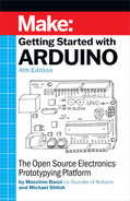
Before you start programming, you need to think about how the hardware will be connected. I like to use a rough block diagram to help me see all the parts I need and to think through how they should be connected. Eventually, you’ll need to know exactly how to connect things, but in the block diagram (Figure 8-1) we just use one line to symbolize some kind of connection.
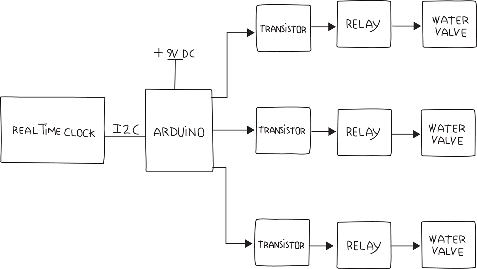
Figure 8-1. Block diagram showing Real Time Clock, Arduino, MOSFETs, relays, valves, and power supplies
In this diagram we assumed three separate water valves, but you can see how this can be generalized to whatever your needs are.
As this is a more advanced project, I’ll introduce construction techniques. This project must work reliably for many months, perhaps even years, so you’ve got a different goal from a simple example that is only meant to show you how something works. The solderless breadboard you used earlier is great for prototyping or experimenting, but for reliability we’ll build this project by soldering components to a Proto Shield. We’ll also consider how to distribute power and make all the connections to the various external parts like the water valves. We’ll even look at how this project could be protected in some kind of enclosure.
Note
Shields are boards that plug into the pins of an Arduino and provide additional functionality. The Arduino Proto Shield is a particular shield that is designed to let you build your own circuit on it.Another feature that is useful as your projects get more complex is an indication of what is going on. This is helpful for debugging, and is especially useful when parts of your system are far away, such as the water valves. We’ll add LEDs to indicate that the water valves are activated. Don’t forget the resistors for the LEDs.
Now that we have a few more details, I like to make a tentative shopping list. With complex systems, I expect that I’ll have to make changes: for example, as I work on the sketch, I might realise that I need another part. (The final, complete shopping list, with links, is at “Irrigation Project Shopping List”.)
Don’t worry if you don’t know what all these parts are. We’ll cover them in detail as we go:
-
One Real Time Clock (RTC)
-
One Temperature and Humidity Sensor
-
One Proto Shield
-
Three electric water valves
-
One transformer or power supply for the water valves
-
Three relays to control the water valves
-
Three sockets for relays
-
Three LEDs as valve activation indicators
-
Three resistors for LEDs
-
One power supply for Arduino (so it will work even when a computer isn’t attached)
Now that you have a tentative list, let’s look at each item and work out the details. Let’s start with the RTC.
Testing the Real Time Clock (RTC)
When I plan to use a device that is new to me, I like to first verify that I understand how it works, before designing the whole system. Because the RTC is new to you, let’s take a look at how it works.
The main part of an RTC is the chip itself. The most common one is the DS1307, which requires a crystal for correct timekeeping and a battery to keep it running when the rest of the system is switched off. Rather than build this ourselves, we’ll use one of the many RTC modules available, saving us time for very little cost.
DS1307 RTC modules are available from many different sources. Fortunately, they all function and interface in very similar ways. I ended up with the TinyRTC, available from Elecrow.
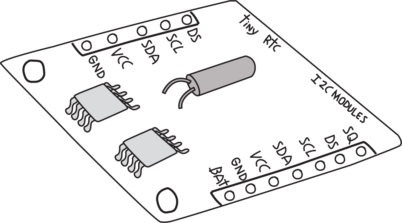
Figure 8-2. TinyRTC Real Time Clock module
Note that the pins are not always included; you may have to order those separately and solder them in. You can get pins from many sources; for example, Adafruit part #392 includes plenty of pins for this and future projects.
Note
If you’re new to soldering, there is a link to a great soldering tutorial in “Soldering Your Project on the Proto Shield”.This device uses an interface called I2C, sometimes also called the Two Wire Interface (TWI) or simply Wire. Arduino provides a built-in library for the I2C interface (conveniently called Wire), and Adafruit provides a library for the DS1307 called RTClib. To install RTClib, do the following in the Arduino IDE:
- Open the library manager by selecting Sketch->Include Library->Manage Libraries
- In the “Filter your search” box type RTCLib
- Click on the “Install” button for the RTClib by Adafruit
- Click on the “Close” button
You can check that you’ve installed the library correctly by checking the example that comes with this library. You don’t need to build a circuit for this, and technically you don’t even need to have your Arduino handy. In the Arduino IDE, open the File menu and select Examples→RTClib→ds1307 to open an example program. Instead of clicking the Upload button, click the Verify button (see Figure 4-2). If you get the message “Done compiling,” then you have installed the library correctly.
Note
After installing a new library, it’s wise to verify that the library is installed properly, and that any libraries it depends on are also installed properly, before you try writing your own program.
Most libraries written for Arduino include examples, and because they were probably written by the same people who wrote the library, they are most likely correct.
The TinyRTC module comes with two sets of pins: one consists of five positions and the other of seven positions. Most of the pins are duplicated, and other pins provide additional features. To test the RTC, you only need to worry about four pins: the two pins that form the I2C interface, power, and ground; the RTC must be provided with 5 V on its pin labeled VCC; and its ground must be connected to the Arduino ground.
Note
On the hardware side, I2C is supported by two specific Arduino pins (SDA and SCL), as described in the Arduino Wire Library reference.For a quick test, you can make use of a common trick: for devices that use very little power, such as the RTC, you can use the digital outputs to provide power by setting one pin to HIGH and another to LOW, if the pins line up properly. An I/O pin that is set to output HIGH is essentially the same as 5 V, and an I/O pin that is set to output LOW is essentially the same as the ground.
On an Uno, SCL is A5 and SDA is A4. In addition to these two interface pins, we need to connect VCC and GND to any other I/O pins to provide 5V and GND. This can be accomplished by aligning the TinyRTC as shown in Figure 8-3 on the Arduino Uno analogue input pins. You could also use a breadboard and jumper wires to make the connection.
Figure 8-3. TinyRTC plugged directly into Arduino Uno analogue input pins. The offset is intentional and enables SCL to plug into A5, and SDA to A4.
Warning
Note that on some Arduinos with different microcontrollers, the I2C signals (SDA and SCL) could be on different pins. For this reason, all recent Arduinos with the Uno R3 footprint comply with a new standard pin layout, which adds the 12C pins after AREF. This is in addition to and duplicates whatever other pins happen to be the 12C pins.
Analogue input A4 and A5 will deal with I2C communication, while A2 and A3 will provide power and ground. A3 needs to provide 5 V to the RTC pin labeled VCC, so we will set it HIGH, while A2 will be set LOW to provide ground.
Now we are ready to test! In the Arduino IDE, open the File menu and select Examples→RTClib→ds1307 to open the example program. Before you compile and upload, remember that you need to set up pins A2 and A3 to deliver power to the TinyRTC. Add the following four lines to setup(), right at the very top:
voidsetup(){pinMode(A3,OUTPUT);pinMode(A2,OUTPUT);digitalWrite(A3,HIGH);digitalWrite(A2,LOW);
Note
If you are using a board that’s wired differently, you’ll need to use a breadboard and jumper wires to connect it, so you should not add those extra lines of code. Just be sure to wire the board as instructed by the supplier.You can also download the example with this modification from the example code link on the book’s catalog page.
While here, note that the example opens the serial port at 57,600 baud.
Now you can upload, and after the upload has completed, open the serial monitor. Check the baud rate selection box in the lower-right corner of the serial monitor, and select “57600 baud”. You should see output resembling this:
2013/10/20 15:6:22
 since midnight 1/1/1970 = 1382281582s = 15998d
 now + 7d + 30s: 2013/10/27 15:6:52

2013/10/20 15:6:25
 since midnight 1/1/1970 = 1382281585s = 15998d
 now + 7d + 30s: 2013/10/27 15:6:55
Note that the date and time may be wrong, but you should see the seconds count increasing. If you get an error, double-check that the RTC is in the right position, i.e., that SCL is connected to A5 etc., and double-check that you set pins A2 and A3 properly in setup().
To set the correct time in the RTC, look in the setup() function. Towards the end you will see this line:
rtc.adjust(DateTime(__DATE__, __TIME__));This line takes the date and time at which the sketch was compiled (__DATE__ and __TIME__, respectively) and uses that to set the RTC. Of course, it might be off by a second or two, but that’s close enough for our purposes.
Copy that line so that it’s outside the if() condition, e.g., just below the rtc.begin():
    rtc.begin();
    rtc.adjust(DateTime(__DATE__, __TIME__));
Compile and upload the sketch, and now the serial monitor should display the correct date and time:
014/5/28 16:12:35
 since midnight 1/1/1970 = 1401293555s = 16218d
 now + 7d + 30s: 2014/6/4 16:13:5
Of course, if your computer has the wrong date and time, this will be reflected here.
After you set the time on the RTC you should comment out the rtc.adjust (and upload the code), otherwise you will keep resetting the time to when that sketch was compiled. This RTC will now keep time for years.
For more information on the library and examples, read Arduino Library and Understanding the Code on Adafruit’s tutorial for theirDS1307 Breakout Board kit.
Note that while the Adafruit board is different, the code is the same.
Now that you feel comfortable with the RTC, let’s move on to the relays.
Testing the Relays
What kind of relays do we need? It depends on how much current the water valves need. Most garden valves seem to use 300 milliamps. This is a small amount of current, and so a small relay is enough. Relays that can be operated at different voltages are available; we’ll use one that uses 5 V so we don’t need another power source. Figure 8-4 shows a popular small 5 V relay.
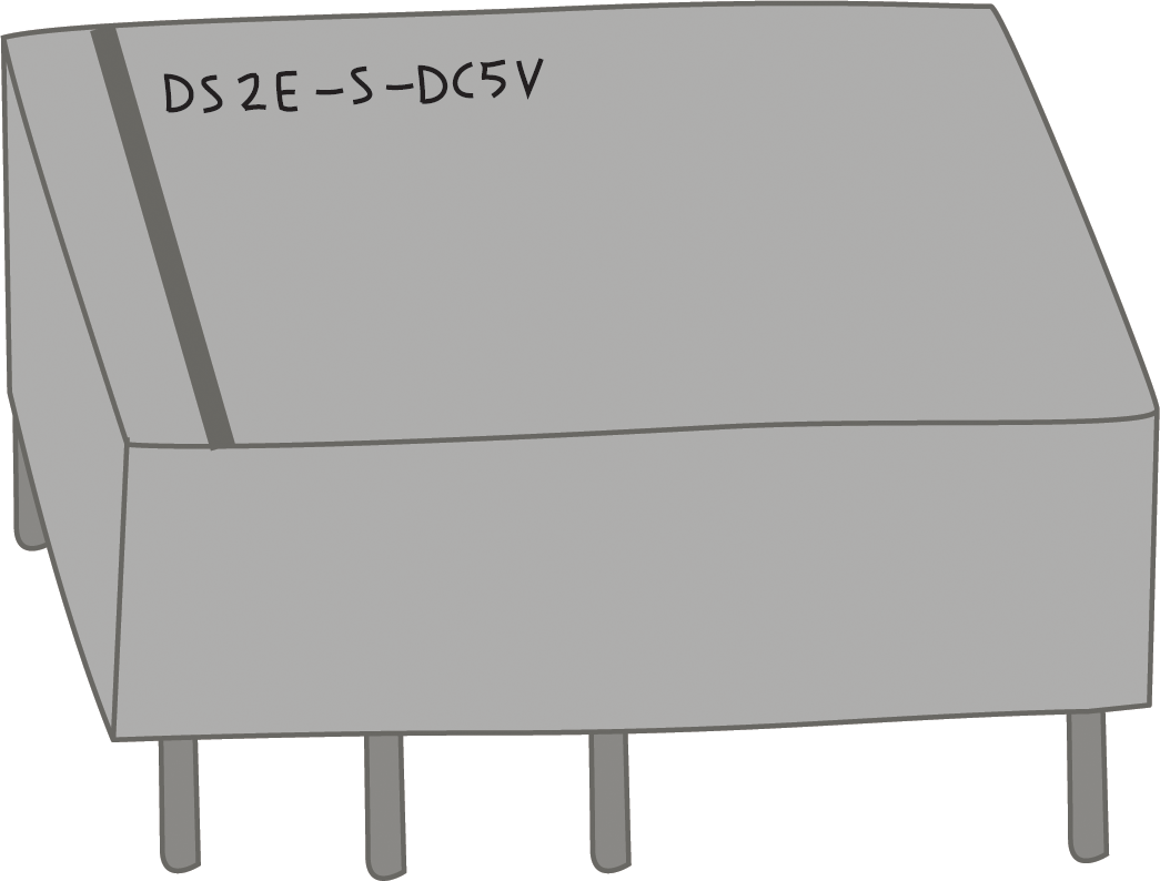
Figure 8-4. 5 V relay
You can buy it at Digi-Key, as well as from many other vendors.
Almost every electronic device has what’s called a data sheet, where all the detailed technical information on the device is documented. It can be a little overwhelming for the beginner, as there is so much information, and usually you need only a very tiny part of it. As you get more experienced, you’ll learn what’s important and how to find it quickly. If you search for the data sheet for the relay we’ve chosen, you’ll see that it can handle up to 2 amps and 30 volts of direct current (DC), or 1 amp and 125 volts of alternating current (AC), which is more than enough for us. This relay also has the advantage of being compatible with our solderless breadboard as well as the Proto Shield you will use later.
Whenever you want to control something with an Arduino output, you have to remember that an Arduino pin should power only devices that use up to 20 milliamps (see “Driving Bigger Loads (Motors, Lamps, and the Like)”). If you search for the current used by this relay in the data sheet, you won’t find it. However, you will find the resistance. Now you have to do some math, because knowing the resistance of the relay (125 ohms) and voltage that Arduino puts out on the I/O pins (5 V), you can calculate the current by using Ohm’s law, which you learned about near the end of “What Is Electricity?”. Dividing the voltage (5) by the resistance (125), we get the current: 40 milliamps.
Since that’s over our limit, we’ll need MOSFETs. For a change, we’ll use a different MOSFET from the one we used in “Driving Bigger Loads (Motors, Lamps, and the Like)”. We’ll use the 2N7000, and you can find its data sheet posted on the Onsemi Semiconductor website.
Just as in “Driving Bigger Loads (Motors, Lamps, and the Like)”, the gate will be controlled by the Arduino I/O pin, and the drain and source will be the switch that will control the relay. You’ll have to to add three 2N7000 MOSFETs to the shopping list, one for each relay.
To avoid the MOSFET gates from floating, add three 10K ohm resistors to your shopping list, one for each relay.
Warning
When you turn on or reset an Arduino, all the digital pins start off as inputs, until your program starts running and your pinMode() changes any pins to outputs. This is important because in that brief period of time, before the pinMode() function changes your pin to an output, the gate will be neither HIGH nor LOW: it will be left floating, which means that the MOSFET could easily turn on, causing the water to come on briefly. While this might not be the end of the world in most projects, it’s a good habit to account for this. As hinted at in “Driving Bigger Loads (Motors, Lamps, and the Like)” in Chapter 5, a 10K ohm between the I/O pin and ground prevents this. 10K ohms is a low enough resistance to make sure the gate doesn’t “float”, but it’s also a large enough resistance that it won’t get in our way when we want to turn on the water.
A resistor used this way is called a pull-down resistor, because it “pulls” the gate down to ground. Sometimes a connection needs to be “pulled” to 5V; in this case, it’s called a pull-up resistor.
Whenever we control a relay or motor, we should add a diode to protect the MOSFETs from the flyback voltage generated by the collapsing magnetic field when the relay is turned off. Although our MOSFET has a built-in diode, it is a relatively small one, so for reliability, it is wise to add an additional, external diode. So, another addition to your shopping list, this time for three 1N4148 (or similar) diodes. While we’re at it, we should add the relay part number, and because we know the type of relay, we can also indicate the correct socket for the relay. Here are the additions that take the shopping list to what we’ll call revision 0.1:
-
Add three MOSFETs to control the relays, 2N7000
-
Add three resistors, 10K ohm
-
Add three diodes, 1N4148 or equivalent
-
Add three relays, DS2E-S-DC5V
Sounds like this circuit is getting complex, doesn’t it? It’s hard to visualise how all the components are supposed to be connected to each other.
Fortunately, a clever system exists for capturing this information. It’s called a schematic diagram.
Electronic Schematic Diagrams
Most electronic circuits are completely defined by two things: 1) which components are used and 2) how they are to be connected. By capturing only this information as clearly as possible, a schematic diagram is the clearest way to visualise and communicate an electronic circuit.
A schematic diagram intentionally does not convey the size, shape, or colour of components, or how they are physically placed next to each other, because this information is not relevant to the definition of the circuit; rather, these are construction details for a particular implementation of that circuit.
Each component is represented by a schematic symbol, which unambiguously identifies the component, but says nothing about its size, colour, etc.
In some cases, schematic symbols look very much like the components they represent, while in other cases they are quite different. In particular, you will see that the schematic symbol for an Arduino does not look at all like an Arduino. From the point of view of a schematic diagram, the only thing that matters about an Arduino is that it has certain pins (power, inputs, outputs, etc.). Thus, it is drawn as a very plain box with just the pins indicated.
Electronic schematic symbols and diagrams are designed to convey their functions as quickly and clearly as possible, and some conventions have become common. Two of the most important conventions are as follows:
-
The lowest voltage is shown at the bottom of the schematic diagram, and the highest voltage is at the top. Usually this means that the GND connection is at the bottom and that 5V (or a higher voltage if that’s used) is at the top.
-
The information flows from left to right. Thus sensors and other input devices are shown on the left, and outputs such as motors, LEDs, relays, and water valves are on the right. If the information travels from Arduino to the MOSFET to a relay to a water valve, they will be shown on a schematic diagram in that order from left to right, even though when you build your circuit, you will have different priorities and your layout may be quite different.
The schematic symbol for an Arduino reflects these conventions too: VIN, 5V, and 3V3 are at the top, GND is at the bottom, and the various controls (RESET, AREF, etc.) are on the left because they are inputs to the Arduino. Although Arduino has three GND pins, only one is shown on the schematic symbol since they are electrically identical. Because the digital and analogue pins can be either inputs or outputs, their placement is somewhat arbitrary.
You can learn more about schematic diagrams in Appendix D.
Back to the project at hand: Figure 8-5 shows the schematic diagram for the circuit we’ve been discussing. Remember, the goal is to verify that we can control a relay by using a MOSFET (although the finished system will have three water valves, for the purpose of verifying that the plan works, we need to check only one).
Warning
Note the pin numbers next to the schematic symbol of the relay. These are important because they tell you which pin is connected to what inside. It is critical to understand this in order to wire up your circuit properly. Note that the pin spacing is not equal: pins 1 and 4 are farther apart than pins 4 and 8. Note that there is a black stripe on the top between pins 8 and 9. Finally, note that the pin numbers are as viewed from the bottom.
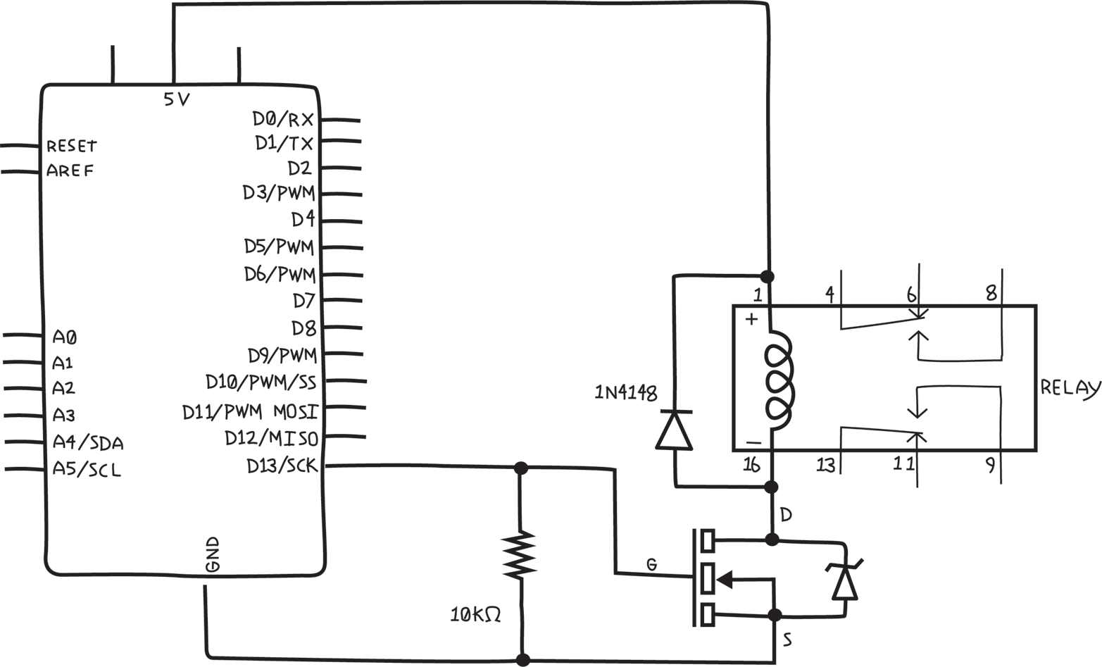
Figure 8-5. Circuit schematic diagram for testing Arduino control of a relay
For reference, Figure 8-6 is a picture of the same circuit on a solderless breadboard in the style we’ve used up to now. You might think of this as a pictorial circuit diagram, as opposed to the schematic in Figure 8-5.
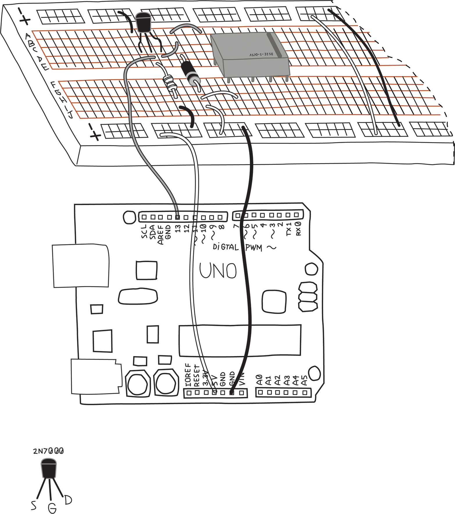
Figure 8-6. Pictorial circuit diagram for testing Arduino control of a relay
Warning
Just like the relay, the MOSFET pins must be properly identified and wired up correctly. Note that the MOSFET has a curved side and a flat side, as shown in Figure 8-6. This is necessary to indicate the proper order of the pins. Be aware that this order is particular to the 2N7000, but is not necessarily universal. Other MOSFETs might have a different order of the pins. You always have to check the data sheet to find the order of pins for your particular MOSFET.
Pay attention to the diodes, MOSFET, and the relay: the diodes are polarized, the MOSFET must have the flat side facing the right way, and the relay needs to have the stripe at the proper end for everything to work.
If you look at Figure 8-5 and Appendix D, you’ll notice that some components, like resistors, light sensors, and (some) capacitors, have circuit symbols that are symmetrical, in that you can flip them upside down and they look exactly the same, while other components, like LEDs, diodes, and MOSFETs, are not symmetrical. Resistors, light sensors, and (some) capacitors are unpolarized, meaning they work the same regardless of which way the current flows through them, while components, like LEDs and diodes, are polarized, meaning they work differently depending on which way the current flows through them. Similarly, MOSFET pins have very specific functions, and can’t be used interchangeably. While not uniformly true, generally components that have symmetrical schematic symbols are unpolarized, and components with asymmetrical schematic symbols are polarized.
Once you’ve built the circuit, the next step is to write the sketch. For testing, I prefer to use one of Arduino’s built-in examples, if possible, since I know the sketch is correct. Because the relay will make a faint clicking sound when activated, if you run the Blink example, you should hear the relay clicking once a second, and you won’t have to write a line of code.
Before uploading the sketch, verify that the sketch is controlling the pin that is attached to the MOSFET. If you have followed the schematic, you will be connected to pin 13, which is in fact the pin that is controlled in the Blink example sketch. Additionally, the LED will blink at the same time the relay should click.
Warning
Before you upload a sketch, it’s a good habit to verify that the pins used in the sketch are indeed the pins that you have wired up. You might have a perfectly correct sketch, and a perfectly built circuit, but if your sketch uses different pins than your circuit, things won’t work, and you might waste lots of time trying to find the problem.
If you don’t hear the relay clicking, check the troubleshooting hints in Chapter 11. Remember, the clicking is very faint; you’ll need to put your ear very close to the relay and be in a very quiet room.
Now we can add the water valve. The water valve will connect to the relay and its own power supply. The water valve and power supply probably come with stranded wire, which is almost impossible to use with a solderless breadboard. You’ll find it handy to attach a short piece of solid-core wire to the stranded wire when you’re working with a solderless breadboard, as shown in Figure 8-7.
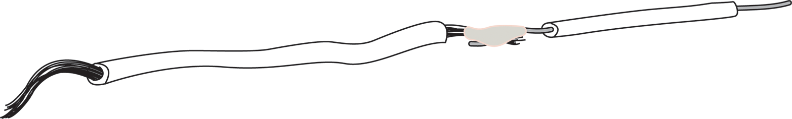
Figure 8-7. Short piece of solid-core wire soldered to stranded wire for solderless breadboard work
You’ll need to insulate the joint with some electrical tape or heat shrink tubing to prevent it from touching a wire that it shouldn’t.
Warning
Whenever you have an exposed piece of metal, such as the wires you just joined together, or the long, bare leads of a photoresistor, or even something that is not part of the circuit, like a screw, you need to make sure that it can’t touch other parts of a circuit, making a connection that you don’t want. This is called a short circuit, and it can make your project fail to work properly. To prevent short circuits, always insulate any exposed wires or secure things in such a way that they can’t move and touch something that they shouldn’t.
You are probably already familiar with electrician’s or insulating tape, which is a common, inexpensive, and easy method. A more professional technique is to use heat shrink tubing. The tubing is cut to size and slipped over the exposed wires or connections, and then heated up with a heat gun, which causes the tubing to shrink tightly around the connection.
At this point you might realise that you’ll need a way to make this connection when you build the final system. There are many ways to do this, but good-quality screw terminals are a great choice, as shown in Figure 8-8.
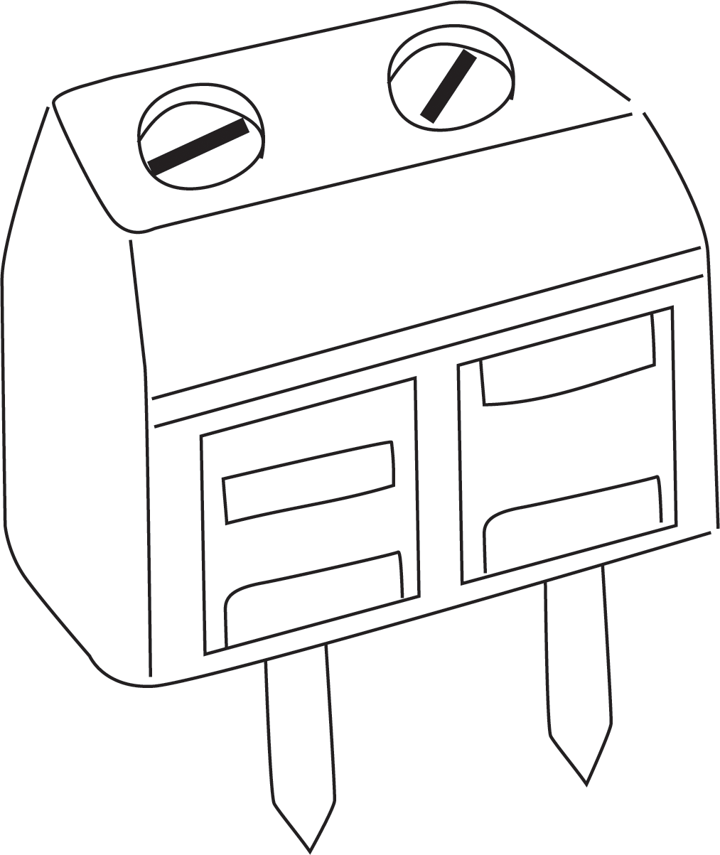
Figure 8-8. Good-quality screw terminal with two positions
So you have another addition to your shopping list. Here are the additions to take us to revision 0.2 of the shopping list:
-
Four two-position screw terminals (one pair for each water valve, plus one pair for the water valve power supply) e.g., Jameco part no. 1299761
Figure 8-9 shows the circuit schematic with the water valve and power supply added.

Figure 8-9. Circuit schematic for testing Arduino control of one water valve
And Figure 8-10 shows the pictorial circuit diagram of exactly the same circuit.
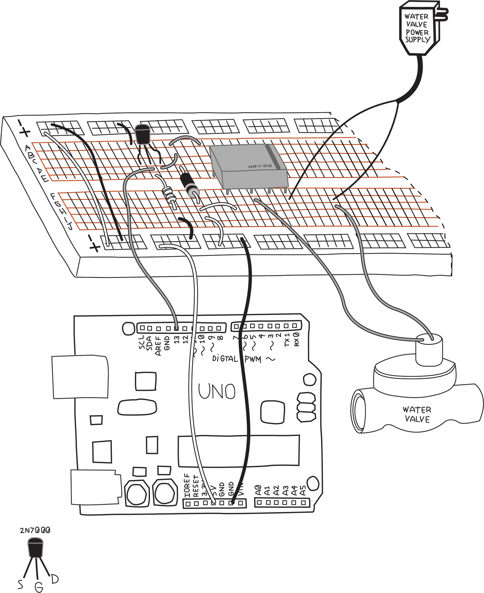
Figure 8-10. Pictorial circuit diagram for testing Arduino control of one water valve
Note
The order of the water valve and the water valve power supply are changed in these two views. I did this to avoid having wires cross in the diagrams for clarity. When connecting a component and a power supply via a switch, the order doesn’t matter, as long as the switch controls whether the circuit is closed or open.You can use the same Blink sketch; you should still hear the relay clicking. You might not hear the water valve clicking, because some water valves work only when they have water pressure inside of them. I was fortunate; my water valves made a very loud click when they were turned on.
What about the LEDs? They can be installed in a number of different places: at the digital outputs, at the MOSFET output, or at the relay output. When possible, I like to put the LED on the farthest point, to verify as much as possible, so let’s put it at the relay output. (If you want, you can put LEDs at all mentioned stages, making it very easy to spot exactly where the signal stops.)
What resistor should we use? This LED will be getting power from the water valve power supply. Most water valves seem to be either 12 or 24 volts. For safety, let’s design for a 24 V system, and if yours is a 12 V system, you can either reduce the value or have a slightly dimmer LED. It should still be quite visible.
LED resistor = (voltage of supply - voltage of LED)/(desired LED current)
Note
If you’re uncertain about what value resistor to use when you’re using it to limit current, it’s always safer to choose a bigger-value resistor. The LED will be visible over quite a wide range of values, and, if it’s too dim, you can always reduce the resistance.
Most LEDs use about 2 volts and are safe below 30 mA, so we have R = (24-2)V/30mA = 733 ohms. You can safely round this up to 1K ohm; the result will be a little less current and a slightly dimmer LED.
But wait, in “Planning”, I told you that some water valves use AC, and then later in “Electronic Schematic Diagrams”, I told you that LEDs are polarized. Polarized means that the LEDs care which way the current flows, and AC means that the current changes direction all the time. Won’t that damage the LEDs? As it turns out, LEDs can withstand a certain amount of voltage in the wrong direction, but if the voltage is too high, the LED might be damaged. Fortunately, other diodes can withstand much higher voltages safely, so let’s use another three 1N4148 diodes to protect the LEDs, giving us an addition that takes the shopping list to revision 0.3:
-
Change quantity of 1N4148 or similar diodes to six
- Specify the LED resistor value is 1K ohm
Figure 8-11 shows the circuit schematic with the LED and diode added. We’ve indicated the polarity of the water valve power supply and of the water valve, but this is relevant only if you have a DC system. If you have an AC system (which seems to be more common), these have no polarity.

Figure 8-11. Schematic diagram for testing the water valve with added LED
And Figure 8-12 shows the pictorial circuit diagram. I’ve left off the resistor values, so make sure you compare with the schematic and get the right resistor in the right place. Also pay attention to the LED and diode polarity—the LED anode connects to the water valve and the diode anode connects to the LED cathode.
Before you plug in the water valve power supply, double check your wiring, especially the relay connections. You don’t want the water valve power supply voltage to get into the Arduino, as it would almost certainly cause damage. Once again, run the Blink sketch. In addition to hearing the relay and possibly the valve clicking, you should see the LED light up.
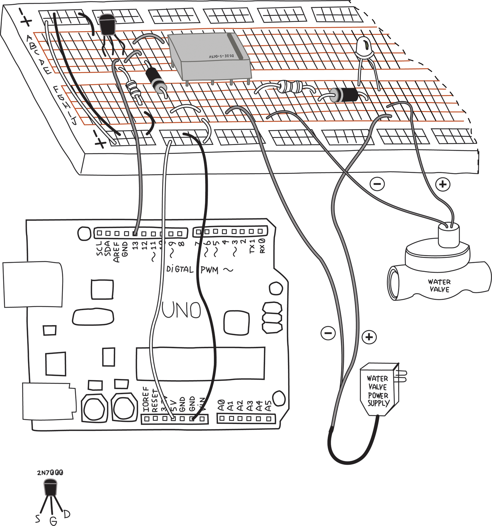
Figure 8-12. Pictorial circuit diagram for testing the water valve with added LED
Now that we have the relay and water valve figured out, let’s test the Temperature and Humidity Sensor.
Testing the Temperature and Humidity Sensor
The DHT11 is a popular Temperature and Humidity Sensor. Like the RTC, it is inexpensive and easy to use with Arduino. According to the data sheet, the DHT11 is connected as shown in Figure 8-13. Note the pullup resistor on the data pin.

Figure 8-13. Schematic diagram for testing the DHT11 Temperature and Humidity Sensor
Because we’re adding a component that needs one, let’s add another 10K ohm resistor to our shopping list. We’re now at version 0.4:
-
Add one resistor, 10K ohm (for Temperature and Humidity Sensor)
Because of the pull-up resistor, we can’t use the trick we did with the RTC (snapping it directly onto the Arduino), so we’ll have to put this on a breadboard (Figure 8-14).
Tip
The schematic diagram of a circuit is the same regardless of whether you build the circuit on a breadboard or in some other way.
Figure 8-14. Pictorial circuit diagram for testing the DHT11 Temperature and Humidity Sensor
You can install the Adafruit DHT11 library exactly as you did the RTClib library.
Check that you’ve properly installed the library by opening the DHTtester example in the DHT category of examples, and then click the Verify button (see Figure 4-2). If you get the message “Done compiling”, you have installed the library correctly.
Before you upload the sketch to your Arduino, note that the example supports three different models of DHT sensors: DHT11, DHT21, and DHT22. To correctly select the proper model, a constant named DHTTYPE is defined to be either DHT11, DHT21, or DHT22:
// Uncomment whatever type you're using!//#define DHTTYPE DHT11 // DHT 11#define DHTTYPE DHT22// DHT 22 (AM2302)//#define DHTTYPE DHT21 // DHT 21 (AM2301)
Notice that DHT11 and DHT21 are ignored, because those two lines are comments or, as programmers say, those lines are commented out. Because you are using a DHT11 sensor, you need to comment out the line with the DHT22, and “uncomment” the line with the DHT11:
// Uncomment whatever type you're using!#define DHTTYPE DHT11// DHT 11//#define DHTTYPE DHT22 // DHT 22 (AM2302)//#define DHTTYPE DHT21 // DHT 21 (AM2301)
The lines with the DHT22 and the DHT21 aren’t doing anything, but they serve to remind us that the library will work with these three sensors, and that this is how you specify which one you are using.
Note
You may have encountered another type of constant: the constant variable. Apart from the awkward name, it too is important and useful.
The differences between a variable (like an integer), a constant variable, and a named constant value are subtle and a bit complicated. In broad terms, a constant variable uses a tiny bit of your Arduino’s memory and obeys scope rules. In contrast, a named constant value does not use any memory and always has global scope.
As a general rule, you should avoid using named constant values and use them only if a library requires them.
You can learn more about named constant values, the const keyword, and variable scope on the Arduino website.
Once you have defined the correct type of DHT sensor, verify that the sketch uses the same pin that you have connected to the sensor, and upload the DHTtester example to your Arduino and open the serial monitor. You should see something like this:
DHTxx test!
Humidity: 47.00 % Temperature: 24.00 *C 75.20 *F Heat index: 77.70 *F
Humidity: 48.00 % Temperature: 24.00 *C 75.20 *F Heat index: 77.71 *F
You can check the humidity sensor by gently exhaling on it. The moisture in your breath should make the humidity rise. You can try to raise the temperature by placing your fingers around the sensor, but since you’re touching the plastic case and not the sensor itself, you may not be able to raise the temperature by much.
Now that you can feel confident in your components, you can start designing the software.
Coding
Guess what? Writing code (coding) requires planning as well. You need to think a little about what you are trying to do before you start typing away. Similar to the way you tested the new electronics before doing the whole design, you’ll test each piece of code before going on. The less code there is, the easier it is to find problems.
Setting the On and Off Times
We want to turn the water valves on and off at different times of the day. We’ll need some way to record those values. Because we have three valves, we might use an array, with one entry for each valve. This will also make it easier if we later want to add more water valves. You might recall that we used an array named buffer (see Example 6-2 in Chapter 6) to store the characters as they were sent from the Processing sketch. Arrays are described briefly in “Variables”.
Here’s one way to do that:
constintNUMBEROFVALVES=3;constintNUMBEROFTIMES=2;intonOffTimes[NUMBEROFVALVES][NUMBEROFTIMES];
Note
For simplicity, we’ll assume you turn the water on and off at the same time every day of the week. As your programming skills increase, you can modify this to accommodate different schedules on different days of the week, and even multiple times in one day. When you start a project, it’s good to start with the most simple system possible, and add features as you verify that things work properly.Note that instead of using fixed numbers for the dimensions of the array, I first created two constant variables. This serves to remind me what these numbers mean, and make it easier to change later. Constant variable names are in uppercase letters to remind us that they are constants.
If you’ve never seen a two-dimensional array, don’t be frightened. Think of it as a spreadsheet. The number in the first [] is the number of rows, and the number in the second [] is the number of columns. A row represents a valve, and we’ll use the first column to store the time at which to turn the valve on, and the second column to store the time at which to turn the valve off.
Let’s make constant variables for the column numbers as well. Remember that the index of elements within an array always starts at zero:
constintONTIME=0;constintOFFTIME=1;
Next we need a way to input this information; that is, some sort of user interface. Typically, a user interface is a menu, but we’re going to make something extremely simple using the serial monitor.
Remember in Chapter 6 we needed a way to tell Arduino what colour to make the light? As I mentioned there, because Arduino is a simple device, we chose a simple way to codify the colour.
We’re going to do a similar thing here: codify the times in as simple a way as possible.
We need to be able to set the ON time and OFF time for each valve. We could use a number indicating the desired valve followed by the letter N for “on” and F for “off,” followed by the time. We could input the time in 24-hour notation, e.g., 0135 for 1:35 a.m. Thus, we would type
2N1345 2F1415
to turn valve 2 on at 1:45 p.m. and off at 2:15 p.m.
To make our life easier, let’s insist that we always use uppercase letters for N and F.
In our code, we would need to parse, or separate, the string that we type into the correct groups.
Note
A group of consecutive characters is called a string.
If you look at the Arduino sketch (Example 6-2), you’ll see we made use of Serial.available() and Serial.read(), which are functions of the serial object. It turns out the serial object has more functions, as described at Arduino.
We’ll use the Serial.parseInt() function, which reads digit characters and converts them to integers. It stops when it sees a character that isn’t a number. We read the letters (N or F) directly with Serial.read().
For the purposes of testing, we’ll just print out the entire array after each line is read, as shown in Example 8-1.
Example 8-1. Parsing the commands sent to the irrigation system
/*Example 8-1. Parsing the commands sent to the irrigation system*/constintNUMBEROFVALVES=3;constintNUMBEROFTIMES=2;intonOffTimes[NUMBEROFVALVES][NUMBEROFTIMES];constintONTIME=0;constintOFFTIME=1;voidsetup(){Serial.begin(9600);};voidloop(){// Read a string of the form "2N1345" and separate it// into the first digit, the letter, and the second number// read only if there is something to readwhile(Serial.available()>0){// The first integer should be the valve numberintvalveNumber=Serial.parseInt();// the next character should be either N or F// do it again:charonOff=Serial.read();// next should come the timeintdesiredTime=Serial.parseInt();//Serial.print("time = ");//Serial.println(desiredTime);// finally expect a newline which is the end of// the sentence:if(Serial.read()==' '){if(onOff=='N'){// it's an ON timeonOffTimes[valveNumber][ONTIME]=desiredTime;}elseif(onOff=='F'){// it's an OFF timeonOffTimes[valveNumber][OFFTIME]=desiredTime;}else{// something's wrongSerial.println("You must use upper case N or F only");}}// end of sentenceelse{// Sanity checkSerial.println("no Newline character found");}// now print the entire array so we can see if it worksfor(intvalve=0;valve<NUMBEROFVALVES;valve++){Serial.("valve # ");Serial.(valve);Serial.(" will turn ON at ");Serial.(onOffTimes[valve][ONTIME]);Serial.(" and will turn OFF at ");Serial.(onOffTimes[valve][OFFTIME]);Serial.println();}}// end of Serial.available()}
You can download this sketch from this book’s catalog page.
After loading the sketch into Arduino, open the serial monitor and check the baud rate and line-ending selection boxes in the lower-right corner of the serial monitor. Select Newline and 9600 baud. The line-ending type makes sure that every time you end a line by pressing the Enter key on your computer, your computer will send a newline character to your Arduino.
For instance, if you want to turn on valve #1 at 1:30 p.m., type 1N1330 and press Enter. You should see this:
valve # 0 will turn ON at 0 and will turn OFF at 0
valve # 1 will turn ON at 1330 and will turn OFF at 0
valve # 2 will turn ON at 0 and will turn OFF at 0
In the sketch, notice that I check to make sure that the character between the numbers is either N or F, and that after the second number is a newline character. This sort of “sanity checking” is handy to catch mistakes you might make while typing, which might confuse your program. These sort of checks are also useful for catching mistakes in your program. You might think of other sanity checks; for instance, you might check that the time is valid, e.g., it is less than 2359, and that the valve number is less than NUMBEROFVALVES.
Note
A program that is designed to handle only the correct data is very delicate, as it is sensitive to any errors, whether caused by user input or a mistake elsewhere. By checking the data before operating on it, your program will be able to identify errors instead of trying to operate with faulty data, which could lead to unexpected or erroneous behavior. This makes your program robust, which is a highly desireable quality, especially since humans won’t always do what they are supposed to do.
Before we go on, I want to show you a new trick. This chunk of code we just developed is lengthy, and we still have a lot to add. It’s going to start getting confusing to read and manage the program.
Fortunately, we can make use of a very clever and common programming technique. In “Pass Me the Parmesan” we explained what a function is, and that setup() and loop() are two functions that Arduino expects to exist. So far you’ve created your entire program within these two functions.
What I didn’t emphasize is that you can create other functions the same way you create setup() and loop().
Why is this important? Because it’s a very convenient way to break a long and complicated program into small functions, each of which has a specific task. Furthermore, since you can name those functions anything you want, if you use names that describe what they do, reading the program becomes much simpler.
Note
Any time a chunk of code that does a specific task becomes large, it is a good candidate for becoming a function. How large is large enough? That’s up to you. My rule of thumb is that as soon as a chunk of code takes up more than two screens, it is a candidate for becoming a function. I can keep two screenfuls in my head, but not more than that.
An important consideration is whether the chunk of code can easily be extracted. Does it depend on many variables that are visible only within another function? As you learn more about variable scope, you’ll see this is important too.
For instance, the code we just developed reads a command from the serial monitor, parses it, and then stores the times into the array. If we made this a function called expectValveSetting(), our loop is simply:
voidloop(){expectValveSettings();}
That’s much easier to read, and most important, easier to understand as we develop the rest of the program.
Of course we need to create this function, which we do like this:
voidexpectValveSettings(){// Read a string of the form "2N1345" and separate it// into the first digit, the letter, and the second number// read only if there is something to readwhile(Serial.available()>0){// ... rest of the code not repeated here}
The rest is exactly the same as Example 8-1; I left out the rest of the function because I didn’t want to waste another two pages.
Now we can turn to the other things we need to do, and make them functions as well.
Checking Whether It’s Time to Turn a Valve On or Off
Next, let’s look at the data from the RTC and figure out how we’ll use this to decide whether it’s time to turn something on or off. If you go back to the RTC example ds1307, you’ll see how the time is printed:
Serial.(now.hour(),DEC);
Conveniently, this is already a number, so comparing with the hours and minutes we have stored will be easy.
In order to access the RTC, you’ll need to add parts of the ds1307 example to your program. At the top, before setup(), add this:
#include <Wire.h>#include "RTClib.h"RTC_DS1307rtc;
This time we won’t use the analogue input pins to provide 5V and GND. Why? Because analogue inputs are scarce; there are only six of them, and we already lost two for the 12C interface to the RTC. At the moment our project doesn’t need any analogue inputs, but we might think of something later.
In setup() you’ll need the following:
#ifdef AVRWire.begin();#else// I2C pins connect to alt I2C bus on Arduino DueWire1.begin();#endifrtc.begin();
Now think about what you need to do: as long as the current time is greater than the time you want to turn a valve ON, and less than the time you want to turn the valve OFF, you should turn it on. At all other times you want it turned OFF.
From the RTC library you can get the current time like this:
dateTimeNow=rtc.now();
and then you can access parts of the time like this:
    dateTimeNow.hour()
    dateTimeNow.minute()
Can you see the problem? We’ve stored time as a four-digit number, where the first two digits are the hour and the last two digits are the minutes. We can’t do a mathematical comparison without separating this number into hours and minutes, and then the comparison gets complicated.
It would be nice if we could have just one number. We can do this if, instead of storing the time as hours and minutes, we just converted the hours to minutes and stored the number of minutes since midnight. That way, we only have to deal with one number and the mathematical comparison is easy. (We have to remember never to turn on the water before midnight and off after midnight. This would be another opportunity for a sanity check to make our program more robust.)
The following code illustrates this:
intnowMinutesSinceMidnight=(dateTimeNow.hour()*60)+dateTimeNow.minute();
and then the comparison looks like this:
if((nowMinutesSinceMidnight>=onOffTimes[valve][ONTIME])&&(nowMinutesSinceMidnight<onOffTimes[valve][OFFTIME])){digitalWrite(??,HIGH);}else{digitalWrite(??,LOW);}
Wait a minute, what about those question marks? We need to know the pin number of each valve. Our for() loop just counts off the valves: 0, 1, and 2. We need a way to indicate what pin number corresponds to which valve. We can use an array:
intvalvePinNumbers[NUMBEROFVALVES];
By using the same constant variable we created earlier, this array will always have exactly the same number of rows as the other array, even if you later change the number of valves.
In setup() we’ll insert the correct pin numbers into the array:
valvePinNumbers[0]=6;// valve 0 is on pin 6valvePinNumbers[1]=8;// valve 1 is on pin 8valvePinNumbers[2]=3;// valve 2 is on pin 3
Note
Whenever you need to look up some information based on an index, an array is a good way to do that. Think of it as a lookup table.
Now we can fix our question marks:
if((now.hour()>onOffTimes[valve][onTime])&&(now.hour()<onOffTimes[valve][offTime])){Serial.println("Turning valve ON");digitalWrite(valvePinNumbers[valve],HIGH);}else{Serial.println("Turning valve OFF");digitalWrite([valve],LOW);}
One last thing: we’re going to need to separate the four-digit numbers in the array into hours and minutes. It might be easier to do that when the user types in the information. We’ll ask the user to add a : between the hours and minutes, we’ll read them as separate numbers, do the conversion to minutes since midnight right there, and store the minutes since midnight in the array. When we print the times we’ll have to convert this back to the usual time format. Example 8-2 now shows our modified expectValveSetting() function along with the new printSettings() function.
Note
You have probably thought of two or three different ways of doing this. Most programming problems, in fact most engineering problems, can be solved many different ways. A professional programmer might consider efficiency, speed, memory usage, perhaps even cost, but as a beginner you should use whatever is easiest for you to understand.
Example 8-2. The expectValveSetting() function
/** Example 8-2. expectValveSetting() and printSettings() functions* Read a string of the form "2N13:45" and separate it into the* valve number, the letter indicating ON or OFF, and the time*/voidexpectValveSetting(){// The first integer should be the valve numberintvalveNumber=Serial.parseInt();// the next character should be either N or FcharonOff=Serial.read();intdesiredHour=Serial.parseInt();// get the hour// the next character should be ':'if(Serial.read()!=':'){Serial.println("no : found");// Sanity checkSerial.flush();return;}intdesiredMinutes=Serial.parseInt();// get the minutes// finally expect a newline which is the end of the sentence:if(Serial.read()!=' '){// Sanity checkSerial.println("You must end your request with a Newline");Serial.flush();return;}// Convert desired time to # of minutes since midnightintdesiredMinutesSinceMidnight=(desiredHour*60+desiredMinutes);// Put time into the array in the correct row/columnif(onOff=='N'){// it's an ON timeonOffTimes[valveNumber][ONTIME]=desiredMinutesSinceMidnight;}elseif(onOff=='F'){// it's an OFF timeonOffTimes[valveNumber][OFFTIME]=desiredMinutesSinceMidnight;}else{// user didn't use N or FSerial.("You must use upper case N or F ");Serial.println("to indicate ON time or OFF time");Serial.flush();return;}printSettings();// print the array so user can confirm settings}// end of expectValveSetting()voidprintSettings(){// Print current on/off settings, converting # of minutes since// midnight back to the time in hours and minutesSerial.println();for(intvalve=0;valve<NUMBEROFVALVES;valve++){Serial.("Valve ");Serial.(valve);Serial.(" will turn ON at ");// integer division drops remainder: divide by 60 to get hoursSerial.((onOffTimes[valve][ONTIME])/60);Serial.(":");// minutes % 60 are the remainder (% is the modulo operator)Serial.((onOffTimes[valve][ONTIME])%(60));Serial.(" and will turn OFF at ");Serial.((onOffTimes[valve][OFFTIME])/60);// hoursSerial.(":");Serial.((onOffTimes[valve][OFFTIME])%(60));// minutesSerial.println();}}
Checking for Rain
What about checking for rain with the humidity sensor? You can do this at the same time you check the time, but it becomes a very long line. It’s OK to use another if() statement; long-time programmers might tell you this is less efficient, but your garden won’t care if the water comes on a split second later. Much more important is that you can read and understand the program.
Warning
Be aware of well-intentioned experienced programmers who might show you clever tricks for reducing the number of lines in your program, or for improving efficiency. As you gain experience, it’s good to understand why these tricks work, but as a beginner, you should always choose whatever is easiest for you to understand.
Example 8-3 shows a way to turn the water on only if it’s not raining.
Example 8-3. Turn on the water only if it’s not raining
if((nowMinutesSinceMidnight>=onOffTimes[valve][ONTIME])&&(nowMinutesSinceMidnight<onOffTimes[valve][OFFTIME])){// Before we turn a valve on make sure it's not rainingif(humidityNow>50){// Arbitrary; adjust as necessary// It's raining; turn the valve OFFSerial.(" OFF ");digitalWrite(valvePinNumbers[valve],LOW);}else{// No rain and it's time to turn the valve ONSerial.(" ON ");digitalWrite(valvePinNumbers[valve],HIGH);}// end of checking for rain}// end of checking for time to turn valve ONelse{Serial.(" OFF ");digitalWrite(valvePinNumbers[valve],LOW);}
Of course we’ll make another function for this. Let’s call it checkTimeControlValves().
We’ll also create a separate function for reading the humidity sensor and the RTC. Let’s call that getTimeTempHumidity().
Now our loop looks something like this:
voidloop(){// Remind user briefly of possible commandsSerial.("Type 'P' to print settings or 'S2N13:45'");Serial.println(" to set valve 2 ON time to 13:34");// Get (and print) the current date, time,// temperature, and humiditygetTimeTempHumidity();// Check for new time settings:expectValveSettings();// Check to see whether it's time to turn any// valve ON or OFFcheckTimeControlValves();// No need to do this too frequentlydelay(5000);}
Putting It All Together
We’re almost done with the sketch. Just a couple of other minor things to consider, and then we can put this all together.
First, what if the user wants to see the current valve schedule? That’s easy, but how does the user tell us? The user could type the letter P for “Print”, but now the sketch needs to be ready for either the letter P or a number. This is tricky; it would be easier if we always expect the first character to be a letter and then decide whether to expect a number. Let’s say that if the first letter is P, then we print the current settings, and if the first letter is S, then we expect a new setting to follow. If the user types anything other than P or S, we’d better remind them what’s OK to type:
/** Check for user interaction, which will* be in the form of something typed on* the serial monitor.** If there is anything, make sure it's* properly-formed, and perform the* requested action.*/voidcheckUserInteraction(){// Check for user interactionwhile(Serial.available()>0){// The first character tells us what to expect for the// rest of the linechartemp=Serial.read();// If the first character is 'P'// then print the current settings// and break out of the while() loopif(temp=='P'){printSettings();Serial.flush();break;}// end of printing current settings// If first character is 'S'// then the rest will be a settingelseif(temp=='S'){expectValveSetting();}// Otherwise, it's an error. Remind the user// what the choices are and break out of the// while() loopelse{printMenu();Serial.flush();break;}}// end of processing user interaction}
The following code is the printMenu() function. It’s short, but we might want to use it elsewhere. Also, in my experience, the menu tends to grow as the project becomes more and more complex, so this function is actually a nice way to document the menu within the sketch. For instance, later you might want to add a menu item to set the RTC time:
voidprintMenu(){Serial.println("Please enter P to print the current settings");Serial.println("Please enter S2N13:45 to set valve 2 ON time to 13:34");}
Note
Any time a block of code is to be used more than once, it is a good candidate for becoming a function, no matter how short it is.
Finally, Example 8-4 shows the entire sketch.
Example 8-4. The irrigation system sketch
/* Example 8-4. The irrigation system sketch */#include <Wire.h>// Wire library, used by RTC library#include "RTClib.h"// RTC library#include "DHT.h"// DHT temperature/humidity sensor library// Analog pin usageconstintRTC_5V_PIN=A3;constintRTC_GND_PIN=A2;// Digital pin usageconstintDHT_PIN=2;// temperature/humidity sensorconstintWATER_VALVE_0_PIN=8;constintWATER_VALVE_1_PIN=7;constintWATER_VALVE_2_PIN=4;constintNUMBEROFVALVES=3;// How many valves we haveconstintNUMBEROFTIMES=2;// How many times we have// Array to store ON and OFF times for each valve// Store this time as the number of minutes since midnight// to make calculations easierintonOffTimes[NUMBEROFVALVES][NUMBEROFTIMES];intvalvePinNumbers[NUMBEROFVALVES];// Which column is ON time and which is OFF timeconstintONTIME=0;constintOFFTIME=1;#define DHTTYPE DHT11DHTdht(DHT_PIN,DHTTYPE);// Create a DHT objectRTC_DS1307rtc;// Create an RTC object// Global variables set and used in different functionsDateTimedateTimeNow;// to store results from the RTCfloathumidityNow;// humidity result from the DHT11 sensorvoidsetup(){// Power and ground to RTCpinMode(RTC_5V_PIN,OUTPUT);pinMode(RTC_GND_PIN,OUTPUT);digitalWrite(RTC_5V_PIN,HIGH);digitalWrite(RTC_GND_PIN,LOW);// Initialize the wire library#ifdef AVRWire.begin();#else// Shield I2C pins connect to alt I2C bus on Arduino DueWire1.begin();#endifrtc.begin();// Initialize the RTC objectdht.begin();// Initialize the DHT objectSerial.begin(9600);// Initialize the Serial object// Set the water valve pin numbers into the arrayvalvePinNumbers[0]=WATER_VALVE_0_PIN;valvePinNumbers[1]=WATER_VALVE_1_PIN;valvePinNumbers[2]=WATER_VALVE_2_PIN;// and set those pins all to outputsfor(intvalve=0;valve<NUMBEROFVALVES;valve++){pinMode(valvePinNumbers[valve],OUTPUT);}};voidloop(){// Remind user briefly of possible commandsSerial.("Type 'P' to print settings or ");Serial.println("'S2N13:45' to set valve 2 ON time to 13:34");// Get (and print) the current date, time,// temperature, and humiditygetTimeTempHumidity();checkUserInteraction();// Check for request from the user// Check to see whether it's time to turn any valve ON or OFFcheckTimeControlValves();delay(5000);// No need to do this too frequently}/* Get, and print, the current date, time,* humidity, and temperature*/voidgetTimeTempHumidity(){// Get and print the current timedateTimeNow=rtc.now();if(!rtc.isrunning()){Serial.println("RTC is NOT running!");// Use this to set the RTC to the date and time this sketch// was compiled. Use this ONCE and then comment it out// rtc.adjust(DateTime(__DATE__, __TIME__));return;// if the RTC is not running don't continue}Serial.(dateTimeNow.hour(),DEC);Serial.(':');Serial.(dateTimeNow.minute(),DEC);Serial.(':');Serial.(dateTimeNow.second(),DEC);// Get and print the current temperature and humidityhumidityNow=dht.readHumidity();floatt=dht.readTemperature();// temperature Celsiusfloatf=dht.readTemperature(true);// temperature Fahrenheit// Check if any reads failed and exit early (to try again).if(isnan(humidityNow)||isnan(t)||isnan(f)){Serial.println("Failed to read from DHT sensor!");return;// if the DHT is not running don't continue;}Serial.(" Humidity ");Serial.(humidityNow);Serial.("% ");Serial.("Temp ");Serial.(t);Serial.("C ");Serial.(f);Serial.("F");Serial.println();}// end of getTimeTempHumidity()/** Check for user interaction, which will be in the form of* something typed on the serial monitor If there is anything,* make sure it's proper, and perform the requested action.*/voidcheckUserInteraction(){// Check for user interactionwhile(Serial.available()>0){// The first character tells us what to expect// for the rest of the linechartemp=Serial.read();// If the first character is 'P' then print the current// settings and break out of the while() loop.if(temp=='P'){printSettings();Serial.flush();break;}// end of printing current settings// If first character is 'S' then the rest will be a settingelseif(temp=='S'){expectValveSetting();}// Otherwise, it's an error. Remind the user what the choices// are and break out of the while() loopelse{printMenu();Serial.flush();break;}}// end of processing user interaction}/** Read a string of the form "2N13:45" and separate it into the* valve number, the letter indicating ON or OFF, and the time.*/voidexpectValveSetting(){// The first integer should be the valve numberintvalveNumber=Serial.parseInt();// the next character should be either N or FcharonOff=Serial.read();intdesiredHour=Serial.parseInt();// the hour// the next character should be ':'if(Serial.read()!=':'){Serial.println("no : found");// Sanity checkSerial.flush();return;}intdesiredMinutes=Serial.parseInt();// the minutes// finally expect a newline which is the end of the sentence:if(Serial.read()!=' '){// Sanity checkSerial.println("Make sure to end your request with a Newline");Serial.flush();return;}// Convert the desired hour and minute time// to the number of minutes since midnightintdesiredMinutesSinceMidnight=(desiredHour*60+desiredMinutes);// Put time into the array in the correct row/columnif(onOff=='N'){// it's an ON timeonOffTimes[valveNumber][ONTIME]=desiredMinutesSinceMidnight;}elseif(onOff=='F'){// it's an OFF timeonOffTimes[valveNumber][OFFTIME]=desiredMinutesSinceMidnight;}else{// user didn't use N or FSerial.("You must use upper case N or F ");$Serial.println("to indicate ON time or OFF time");$Serial.flush();return;}printSettings();// print the array so user can confirm settings}// end of expectValveSetting()voidcheckTimeControlValves(){// First, figure out how many minutes have passed since// midnight, since we store ON and OFF time as the number of// minutes since midnight. The biggest number will be at 2359// which is 23 * 60 + 59 = 1159 which is less than the maximum// that can be stored in an integer so an int is big enoughintnowMinutesSinceMidnight=(dateTimeNow.hour()*60)+dateTimeNow.minute();// Now check the array for each valvefor(intvalve=0;valve<NUMBEROFVALVES;valve++){Serial.("Valve ");Serial.(valve);Serial.(" is now ");if((nowMinutesSinceMidnight>=onOffTimes[valve][ONTIME])&&(nowMinutesSinceMidnight<onOffTimes[valve][OFFTIME])){// Before we turn a valve on make sure it's not rainingif(humidityNow>70){// It's raining; turn the valve OFFSerial.(" OFF ");digitalWrite(valvePinNumbers[valve],LOW);}else{// No rain and it's time to turn the valve ONSerial.(" ON ");digitalWrite(valvePinNumbers[valve],HIGH);}// end of checking for rain}// end of checking for time to turn valve ONelse{Serial.(" OFF ");digitalWrite(valvePinNumbers[valve],LOW);}Serial.println();}// end of looping over each valveSerial.println();}voidprintMenu(){Serial.println("Please enter P to print the current settings");Serial.println("Please enter S2N13:45 to set valve 2 ON time to 13:34");}voidprintSettings(){// Print current on/off settings, converting # of minutes since// midnight back to the time in hours and minutesSerial.println();for(intvalve=0;valve<NUMBEROFVALVES;valve++){Serial.("Valve ");Serial.(valve);Serial.(" will turn ON at ");// integer division drops remainder: divide by 60 to get hoursSerial.((onOffTimes[valve][ONTIME])/60);Serial.(":");// minutes % 60 are the remainder (% is the modulo operator)Serial.((onOffTimes[valve][ONTIME])%(60));Serial.(" and will turn OFF at ");Serial.((onOffTimes[valve][OFFTIME])/60);// hoursSerial.(":");Serial.((onOffTimes[valve][OFFTIME])%(60));// minutesSerial.println();}}
You can also download this sketch from from the example code link on the book’s catalog page.
Assembling the Circuit
Finally, we’re done with the sketch and we’ve tested all the components! Are we ready to start soldering? Not quite: we’ve tested the various components separately, but not together. You might think that this step is unnecessary, but integration testing is vital. This step discovers unexpected interactions between components, whether hardware or software. For instance, two components might require the same feature on Arduino that is available on only one pin, or two libraries might conflict with each other, or the sketch logic might need to be reorganised. It’s better to do this on the solderless breadboard in case wiring changes need to be made.
To get our full automatic garden-irrigation system, we need to combine three schematics: Figure 8-11, Figure 8-13, and the schematic for the RTC. Although our final system will have three valves, it will be quite a lot of work (and quite a squeeze for the solderless breadboard), for not much gain in information. If it works for one water valve, it should work for all three, so let’s do just one valve for now.
Warning
Be very careful making assumptions, as they may be wrong and could come back to haunt you later. Never assume that if things work OK by themselves that they will work well together. Any engineer will tell you that integration testing is vital and very often finds problems that were not seen earlier.
Notice that I made an assumption: that testing with only one valve would be sufficient. This is exactly the sort of assumption I’m warning you against. For instance, more valves and more relays consume more power. Can the Arduino digital outputs provide power to all three relays if they are all on at the same time? Can the water valve power supply provide power to all three water valves if they are all on at the same time?
I’ve allowed myself to make these assumptions because I’ve done the rough calculations in my head, and because my years of experience tell me this is very low risk. However, as a beginner, you should avoid making such assumptions and test everything before you start soldering or assembling a project inside a case.
I’ve seen too many students have to take beautifully constructed projects apart because something didn’t work the way they expected it to. (Even worse, it always seems to be the part that’s hardest to get to.)
—Michael
Figure 8-15 shows the schematic and Figure 8-16 the pictorial circuit diagram for the entire system for one valve. Again, I’ve indicated the polarity of the water valve power supply and of the water valve, but this is relevant only if you have a DC system. If you have an AC system (which seems to be more common), these have no polarity.
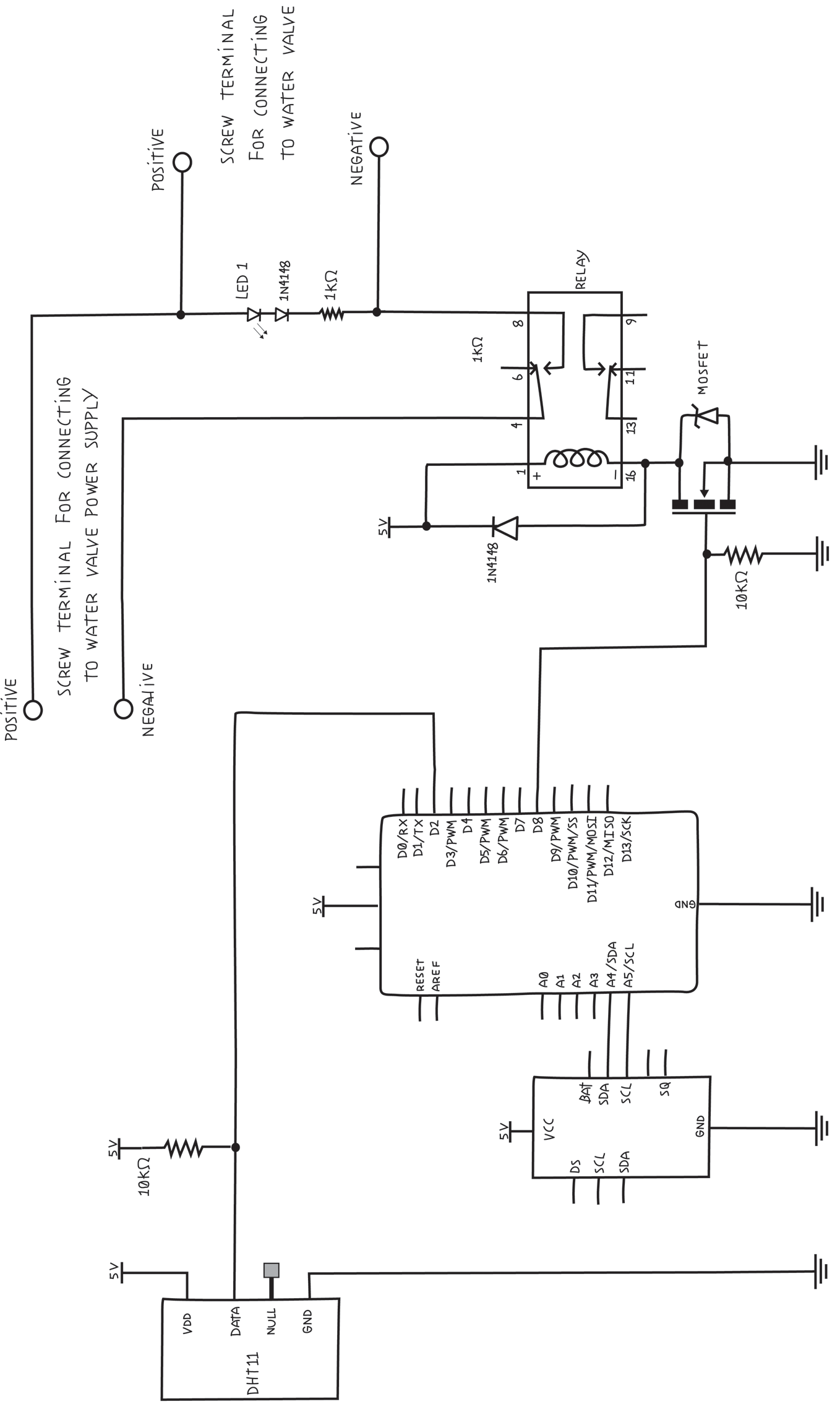
Figure 8-15. Circuit schematic for full automatic garden-irrigation system, one valve
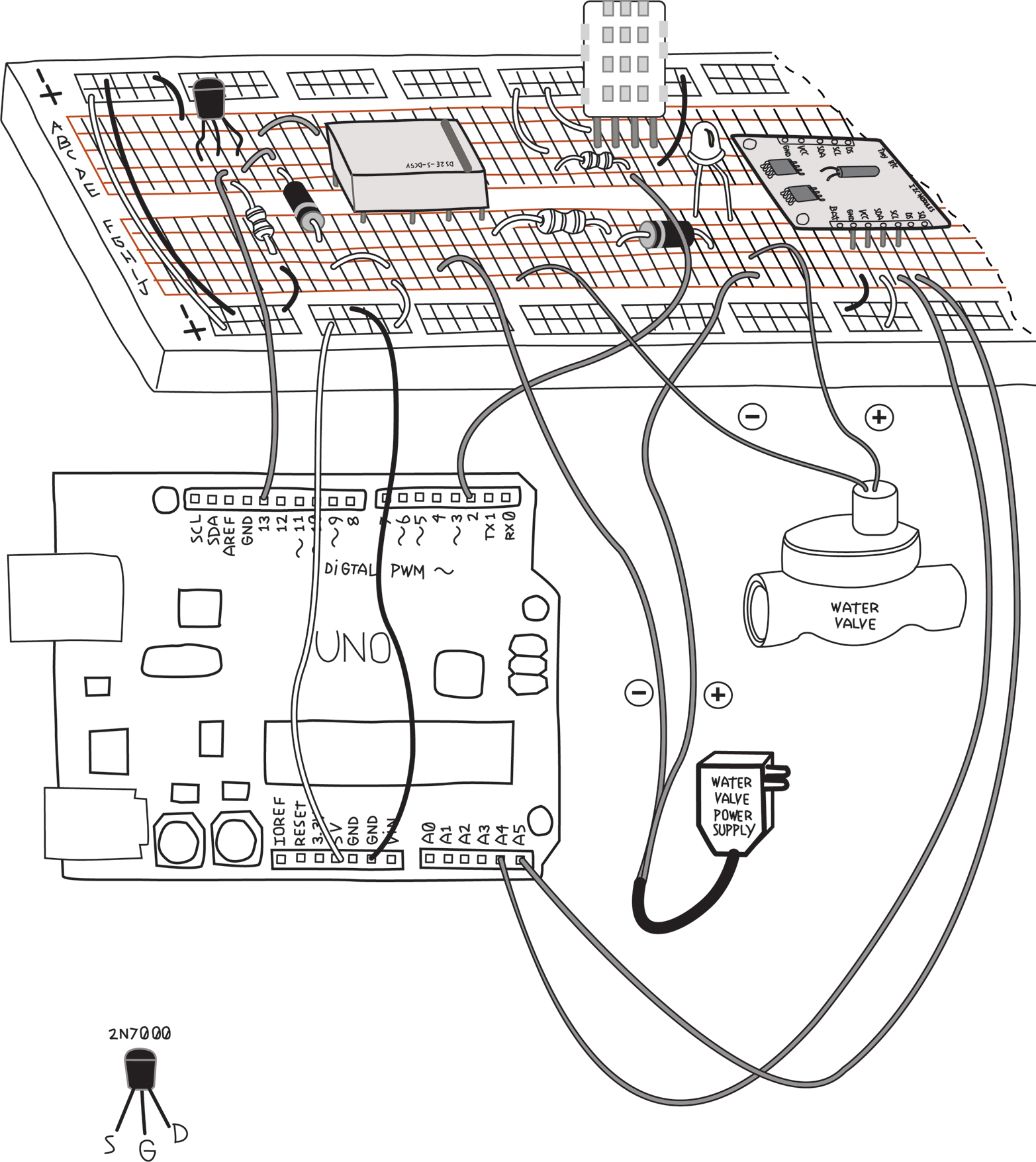
Figure 8-16. Pictorial circuit diagram for full automatic garden-irrigation system, one valve
Note
Before building a complex circuit, print out the schematic. As you build your circuit, use a coloured pen or highlighter to mark each connection you make. This will make it easy to see what you’ve done and what you’ve not yet done.
This is also useful when verifying a circuit, marking each connection as you verify it.
Build this on your breadboard and upload the complete system sketch from Example 8-4. It’s OK that the sketch assumes three valves and we have only one: you can set times and allow the other two to activate, but nothing will happen.
Now test it: Press P to display the current settings and verify that they are all zero. Note the current time. Press S and set an ON time that is a minute or so away, and then set an OFF time for a minute after that. Your relay should click and the LED should come on. Your water valve may or may not do anything, depending on whether it works without any water pressure (mine makes a very reassuring click even without water).
Problems? Double-check your wiring. Pay particular attention to the diodes, the MOSFETs, and the relay. Remember that each pin of the MOSFET has a particular function, and you must use the correct pin. Remember that the diode is polarized. The black band indicates the cathode. Remember that the relay has a black strip indicating pins 8 and 9. If your water valve power supply and water valves use direct current (DC), make sure the positive and negative ends are connected where they are supposed to be. Check out Chapter 11.
This step also helps remind you of the importance of getting the MOSFETs, diodes, and relays wired up the right way. Once you solder these components, it won’t be so easy to change. So once you get things working, make sure you understand why. Make notes of any mistakes you made and how you fixed them. You might even want to take some pictures of your breadboard for reference. It’s always a good idea to document your work.
Once you’re happy with that, you can move on to the Proto Shield.
The Proto Shield
As I mentioned earlier, we’ll use the Proto Shield because it provides a secure and easy way to connect a project to Arduino. You can buy this from the Arduino Store. There are many other Proto Shields available. Any will work, but you may have to make changes to the layout to fit your particular shield. Some shields come with the pins, while others require that you buy them separately.
As you can see, the shield has pins on the bottom that will plug into your Arduino, bringing all the Arduino pins to the shield. The shield has holes next to each Arduino pin for soldering wires, which are connected by the shield to the Arduino pin. To make a connection to an Arduino pin, simply solder a wire into the corresponding hole. This makes a much more reliable connection than poking the wires in to the headers as we’ve done in the past.
Most of the shield is taken up by a grid of tiny holes. They are a little like the holes on the solderless breadboard, in that you can place components and wires anywhere (almost) that you like, but unlike the solderless breadboard, very few connections are provided. You will be making most of the connections by soldering wires directly to the components, usually on the bottom of the board. You can minimize the number of connections you have to wire yourself by making clever use of any busses or other connected holes the shield offers.
Note
When using a Proto Shield, or in fact any perforated soldering breadboard, it is common to put the components and wires on top and do the soldering on the bottom. This is especially important with a Proto Shield, as the bottom of the shield will be quite close to the Arduino, and there isn’t much room there. Remember that none of your connections on the bottom of the shield must touch any metal on top of the Arduino, such as components, traces, or the USB port.
If you do have to place any components or wires on the bottom, make sure they are as flat as possible.
Laying Out Your Project on the Proto Shield
The first step is to think about what needs to fit on here, and where they will be. We need to make room for the MOSFETs, relays, LEDs, and screw terminals. The screw terminals should be along a side that is accessible, and it would be nice if the LEDs were near the appropriate screw terminals. The MOSFETs are pretty small and can go anywhere, but it would be nice if each were next to the relay it controlled.
The relays are the biggest objects, so we need to give them space before we fill up the shield.
Warning
It’s easy to confuse the top of the shield and the bottom, so make sure you place the components on the right side. I have written TOP and BOTTOM on the following illustrations to remind you. I suggest you write TOP and BOTTOM on your shield with a permanent marker.Warning
Make sure you don’t use any holes that already have a function, such as the ICSP connector or the lone ground not far from the IOREF pin. In the illustrations, I have indicated these holes with a black-filled circle.Avoid the area that sits above the USB connector. If you are using the Arduino Proto Shield, this area is intentionally free of holes.
Note
Whenever you are soldering a circuit, think about where you will place things before you start any soldering. Start with connectors and the big items, and then place the smaller components close to where they need to connect. You can use the leads of the components to make the connections by bending the leads over on the underside of the shield and soldering them directly to the correct pins.
Don’t solder anything until you are happy with the placement. Document your placement either by drawings or photographs before you begin soldering, in case anything falls out before you solder it into place.
I promised I’d explain what the sockets are for. You can see that the relays would have to be soldered into the Proto Shield. What happens if one of the relays goes bad? Happily, the relays will fit a socket. The socket gets soldered onto the Proto Shield, and the relay plugs into the socket.
If the relays get sockets, why doesn’t every component get a socket? For a couple of reasons: resistors are easy to remove by desoldering. In the worst case, they can be cut out. Same thing for the MOSFETs. The relays would be very hard to desolder because they have eight pins. By the time we heat up the second pin, the first would have cooled down already. Also, once the relay is soldered in place, it’s impossible to cut it out. Finally, the relay is a mechanical device with moving parts, and moving parts are more likely to fail than purely electronic parts. (Still, the relay should work for many years.)
Note that the sockets have an orientation: there is a small semicircle in the plastic indicating the top, or where pin 1 goes. The socket really doesn’t care; it would work either way. This is meant to help you put the component in the right way around, so make sure you put the socket in facing the way you intend to wire it up. Again, making drawings and notes to yourself will help you later. Remember that when you flip the shield over, the orientation of the sockets will be reversed. I like to draw a circle around pin 1 of each socket on the bottom side of the board, to make sure I’m oriented properly.
When you flip the shield over, the sockets will fall out, so bend the leads over to hold them in place. They can be bent almost all the way as long as they don’t touch any other holes.
Note
Whenever you are soldering a circuit, use sockets for relays and chips.
Figure 8-17 shows one possible layout.
Note that I have distorted the image a little to enlarge certain areas. We’ll be doing lots of work there later, and I wanted to make it easier to see the details. The number of holes and the orientation of the rows and columns is accurate.
As we add the smaller components, I’ll show you a trick. We’ll make use of their leads to make some of our connections.
Look at the schematic. You’ll see that the three diodes that go near the relay go from pin 1 to pin 16. If we place the diodes on that end, we can just bend the leads over on the underside of the shield and solder them directly to the correct pins. Make sure you observe the polarity of the diodes or you’ll be cursing later. (I know because I’ve done that many times too.) The cathode is indicated by the ring near one end of the diode, and it goes to pin number 1 of the socket.

Figure 8-17. One possible way to place the large components on the Proto Shield (note the orientation of the relay sockets)
Bending the leads of the diode also helps keep it in place when you flip over the shield to solder the bottom.
The MOSFET has one pin (the drain) that is connected to the relay pin 16. Let’s place that right next to the diode, and we can bend the MOSFET lead over and solder it to the diode. The 10K ohm resistor that connects the gate of each MOSFET to the GND can go between the gate and the source of the MOSFET, since the source also goes to GND. We do this by standing the resistor on its end and using the resistor’s leads to make the necessary connections, without having to add any wire.
Try to get all components as close to the shield as possible. The diodes should lie flat against the shield. You can bend the leads of the MOSFETs a little to make them low, but don’t bend them too much or they will break. The resistor is standing, but one end of the resistor should be sitting on the shield.
I’ll show you how to make all these connections in a moment.
Figure 8-18 shows the top view with the relay sockets, MOSFETs, diodes, and resistors added.
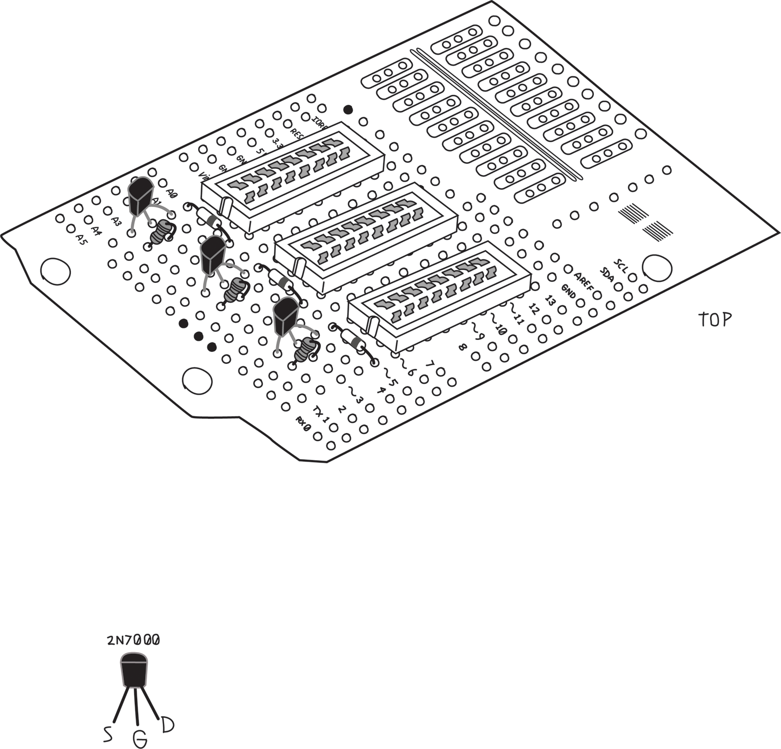
Figure 8-18. Top view with the relay sockets, MOSFETs, diodes, and resistors added
What about the RTC and DHT11? The DHT11 needs to be out in the garden on four long wires. Rather than solder these wires directly to the Proto Shield, we’ll solder a strip of pins to the wire and mount a strip of sockets on the shield so that we can unplug it if necessary. I’ll show you how to do this later. The 10K ohm resistor (on the data pin of the DHT11) can be made to fit almost anywhere, so leave that for later.
The RTC already has pins, so another socket will be perfect for the RTC. Remember that the RTC takes up quite a bit of space, so place this somewhere where there is room. The top edge of the board, after the MOSFETs and their related circuitry, might be a good place. I placed them in the very last row. This still left me an empty row between the MOSFETs and the sockets for any related wiring, as shown in Figure 8-19.
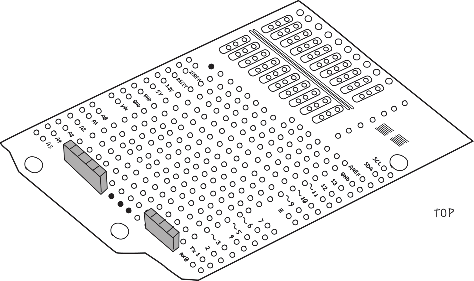
Figure 8-19. A four position socket for the DHT11 sensor and a five position female header for the RTC
Note
Whenever you have to attach long wires from elsewhere to a board, don’t solder the wires directly to the board. Instead, use a connector of some sort to make it easy to remove. A pair of pins and sockets of the right number of positions make a good, inexpensive choice for small wires; screw terminals are good for larger wires.
Whenever you have to attach a module with headers to a board, don’t solder the module headers directly to your board. Instead, mount a corresponding header of the other gender on your board. This will allow you to remove the module in case you need to for any reason.
Better add all these headers to the shopping list! These headers usually come in long strips and often multiple pieces. They are designed to be cut to whatever length you need. When you cut the pins, you can usually break the strip exactly where you need it. When you cut the sockets, you have to sacrifice one position. Here are the additions that take our shopping list to version 0.5:
Soldering Your Project on the Proto Shield
For a great tutorial on how to solder, study the “Adafruit Guide to Excellent Soldering.”
Now, finally, you’re ready to start soldering!
Warning
Don’t rush. Be careful. Remember to breathe and relax. Double-check the schematic for each connection before you solder it. Inspect your work often for bad solder joints or other mistakes.
Don’t try to make all the connections at once. Do them in small groups, and take a short break between groups. When you come back, double-check what you just did.
Try not to follow my directions blindly. Try to understand what’s being done and make sure you agree with it.
You can remove the screw terminals and the sockets for now so that you can place the shield flat on your work surface to keep the parts in place.
Solder the sockets in place first to keep them from falling out. This will also give you a chance to practice soldering a little.
Next come the sets of diode, MOSFET, and resistor. Remember that we wanted to use their leads (on the bottom of the board) to make the connections. Bend them over very flat against the board so that the components are pulled tight against the board, and then over to where you need to make the connection. You don’t need to wrap the lead around the pin; it’s enough that the lead overlaps the pad around the pin. Make sure the solder flows onto all leads that are being connected.
When you’re done soldering a connection, cut any excess leads as close as possible to the solder joint. You don’t want any extra bit poking out that might touch something else later. This is detailed in the “Making a good solder joint” tutorial by Adafruit.
Warning
When you trim a lead or wire after soldering, make sure you catch the piece you cut off and throw it away, to make sure it does not fall back on your work, where it might touch something it shouldn’t and make a short circuit.The MOSFET source pins all go to GND, so they chould be connected together. You can use the long leads of the resistors to connect all three together, which will provide a useful GND strip for anything else that needs to be connected to GND. These common strips are often called buses. Note that at this point our GND bus is not yet connected to the Arduino GND. I usually leave that for later so as not to occupy a hole that I later might need, but we have to remember to make this connection at the end.
Figure 8-20 shows the bottom view, with all the leads folded over and soldered in place. The shadowed areas indicate the relay sockets on the top side, and the cones indicate the solder.
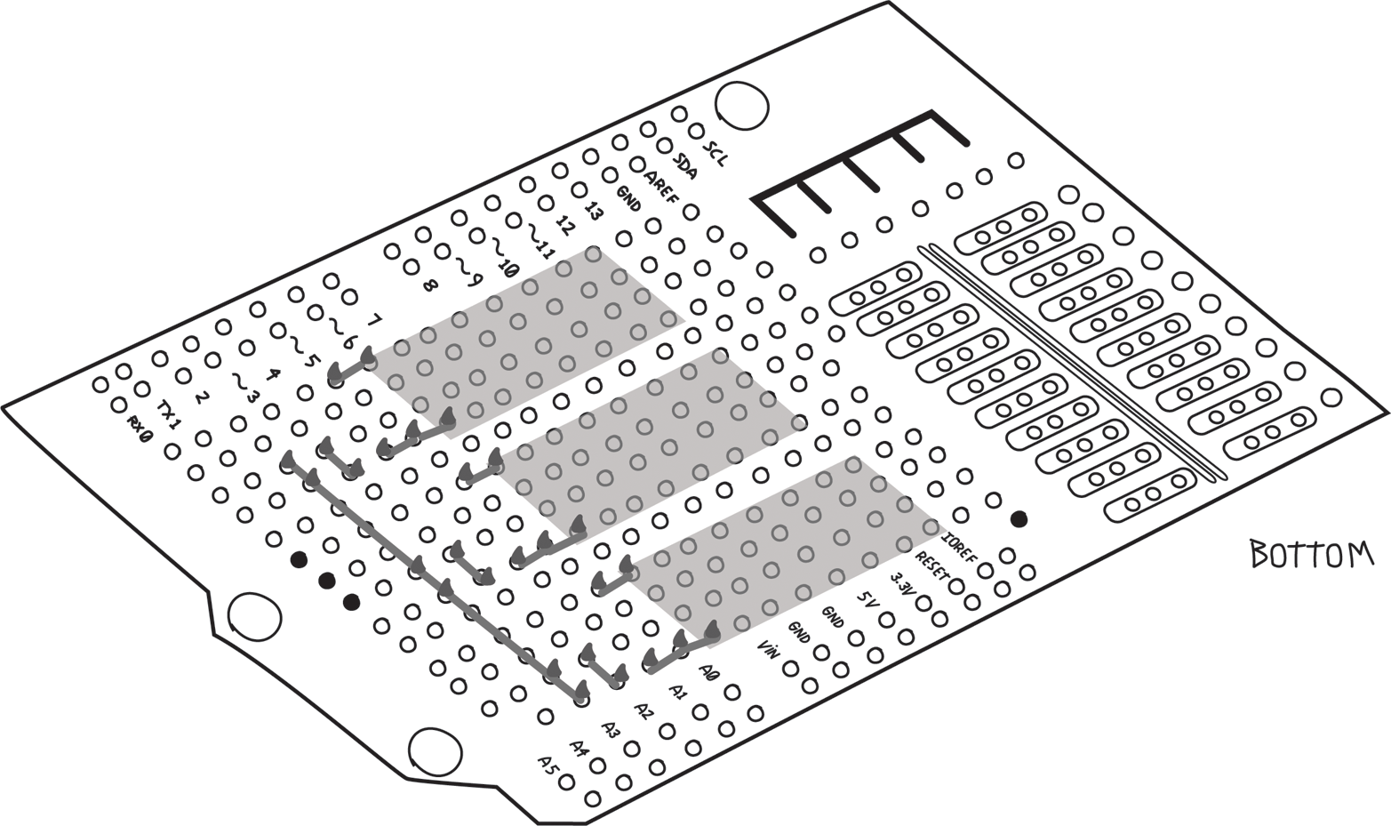
Figure 8-20. Bottom view of the relay socket, MOSFET, and diode
Now you can replace the screw terminals. Before you solder them in place, make sure the openings for the wire are facing the right direction, towards the outside of the board! (Another mistake I learned the hard way.) As always, make sure they are flush against the shield. Leave the sockets for later.
At this point it’s a good idea to decide which screw terminal is what. Document this as shown in Figure 8-21 so that you don’t forget and make the wrong connection later.
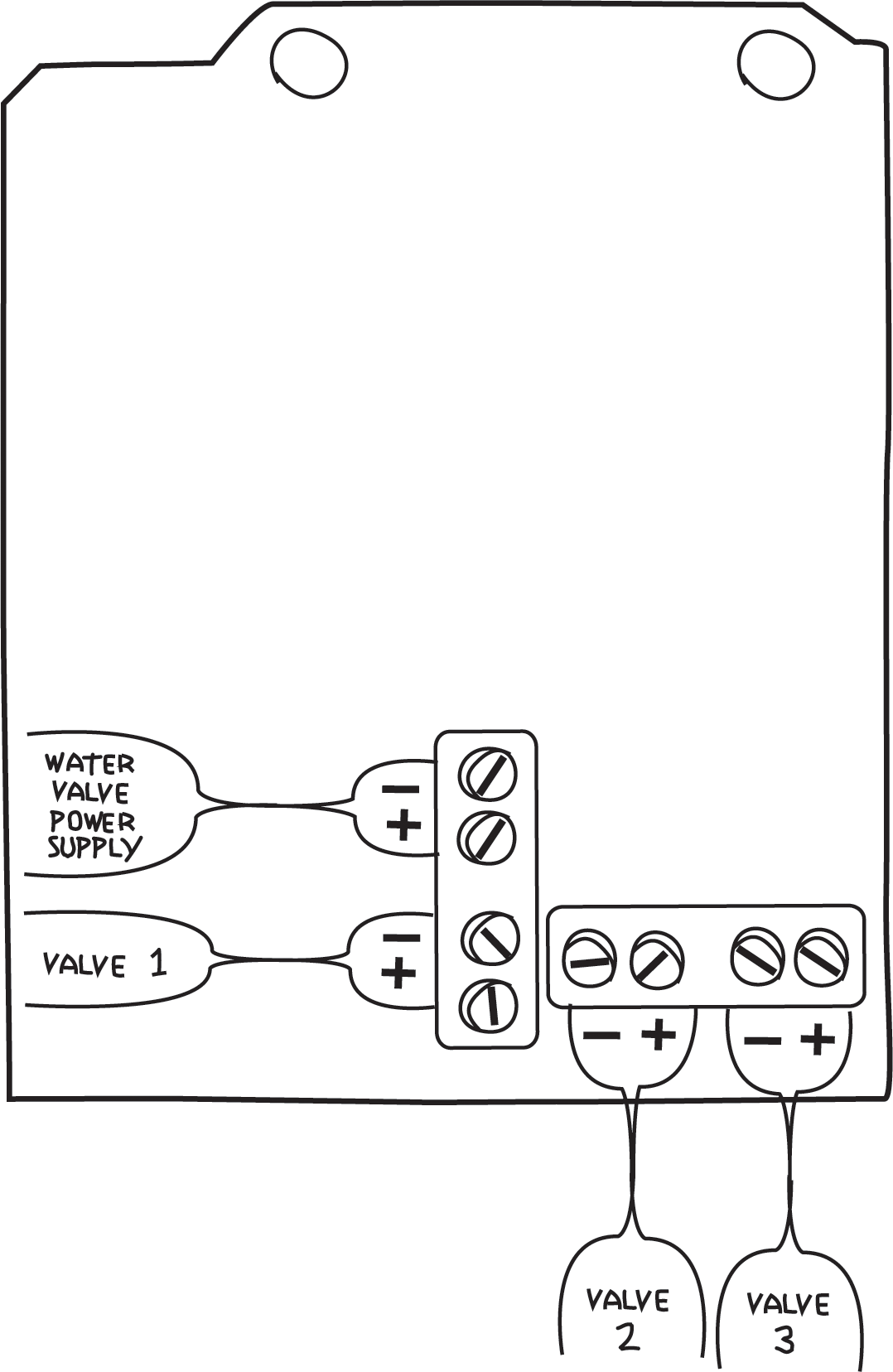
Figure 8-21. Documenting which screw terminal does what
Now you can add the indicator LEDs and their associated diodes and resistors. Again, by cleverly placing these components, you can use the component leads to make the connections. Note that this particular Proto Shield has some rows of three connected pins. I used these to help with the connections. Remember that LEDs and diodes are polarized: the anode (longer lead) of each LED goes to the screw terminal, and the anode of each diode goes the cathode of its LED.
It’s important to note that there are two strips (buses) of 5V and GND that we’re not using, so you have to carefully make sure the LED leads are above these and do not touch them. If the LED accidentally touched 5V or GND, this could bring the 24 V from the water valve power supply into Arduino, which would probably damage the Arduino. To be safe, you can cut a piece of electrical tape to the proper size and tape it over the 5V and GND buses. These buses are on the bottom side as well and must be avoided there too.
In Figure 8-22 we’ve shown the components quite high so that you can see where they are all connected, but when you build the circuit, place them as close to the shield as possible, as mentioned earlier. Remember that this illustration is distorted to enlarge certain details, but that the holes used are accurate.
In this and many of the following figures I’ve left off most of the components from previous steps so that you can see more clearly the components and locations of each step.

Figure 8-22. Top view showing LED, resistor, and diode placement
Figure 8-23 shows the bottom view. As before, we’ve used the component leads to make connections to each other and to the screw terminals. It’s a good thing we documented the screw terminals, because we’d get confused now as to which one does what.

Figure 8-23. Bottom view showing LED leads soldered to screw terminal pins
Note the black circle near IOREF. That’s a ground connection and must not be used unless you’re making a connection to ground.
This is a complicated section. Study it carefully and don’t solder anything until you are sure you understand what it’s doing and are convinced it’s going to the right place.
Now that all the components are on the shield, you have to wire up the remaining connections; use 22 AWG solid-core wire. Smaller would work as well but might be harder to work with. Use whatever works for you.
Note
Choose a consistent color scheme: use red wire for anything connecting to 5V and black wire for anything connecting to ground. You can make up your own colour coding for the others, but don’t use red or black for anything else. You might want to use orange for the water valve power supply positive connections, and green for the water valve power supply negative connections. Any wires that connect together should be the same colour, and any wires that do not connect together should be different colours.The general principle is this: wires go on the top, and into holes that are next to the pin you need to connect to. On the bottom, you fold the wire over and solder to the appropriate pin, just as you did earlier with the component leads.
All the Arduino pins have their own holes, so you don’t need to fold the wire over. Just solder the wire in the appropriate hole.
Sometimes you simply can’t get close to the pin you need from the top. In these cases, it’s OK to put the wires on the bottom, but make sure to keep them as flat as possible.
Let’s start with the MOSFETs and their related circuitry. We’ve made all the connections we could with the leads. We need to connect the pin number 1 of all the relays to 5V. I’ve added red wires to make the 5V connection as shown in Figure 8-24 (remember the GND connection we’ll make at the end).
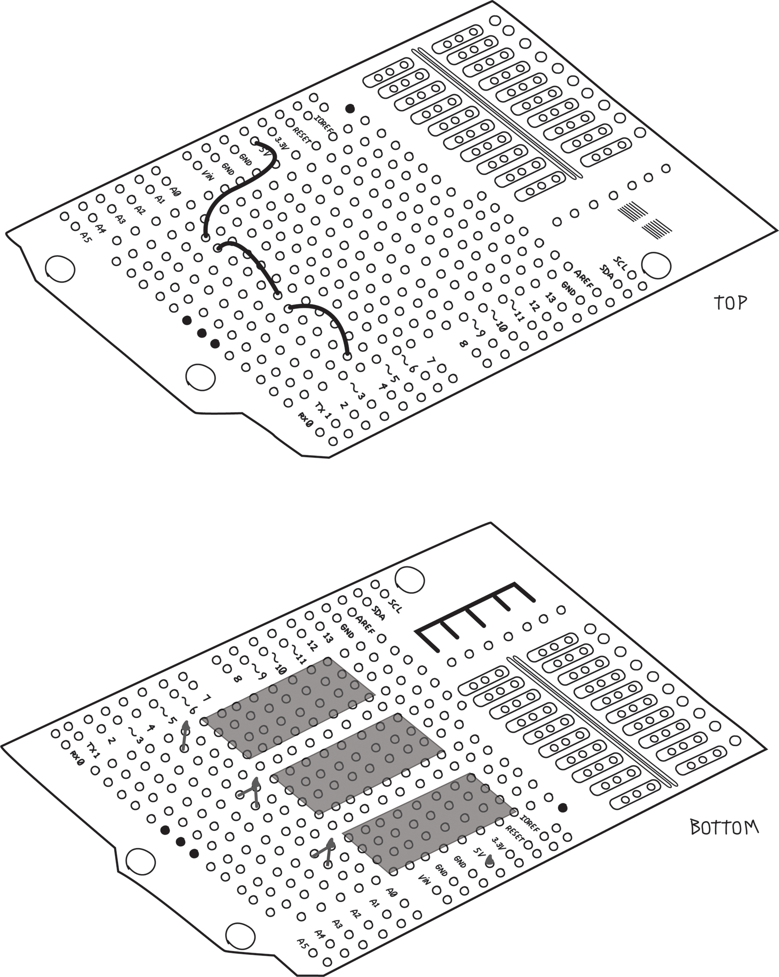
Figure 8-24. Making the 5V connections to the relay circuitry
Next, connect all the positive screw terminals. This is all done on the bottom of the board, as shown in Figure 8-25. Make sure not to allow any leads or solder to touch those 5V and GND buses!
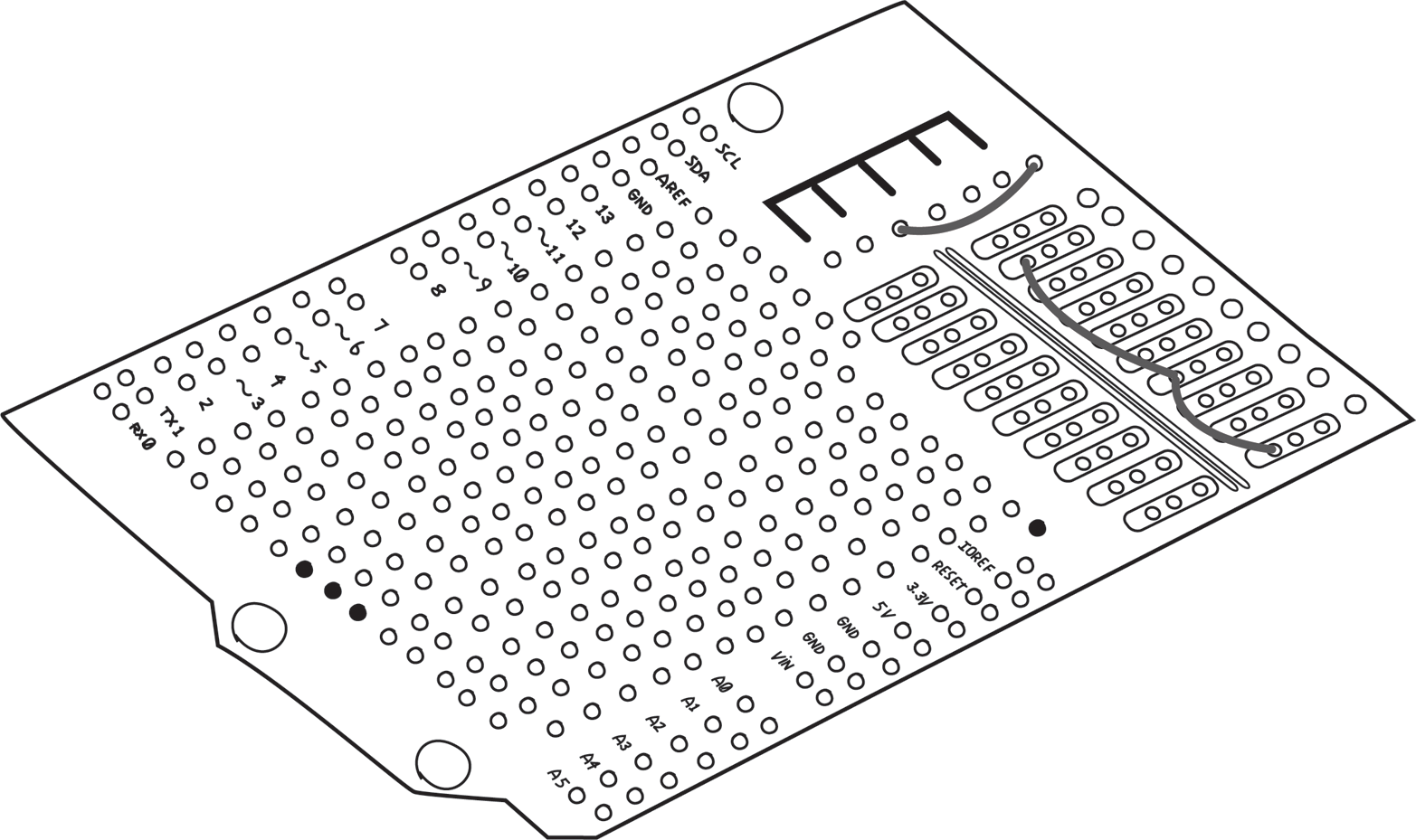
Figure 8-25. Connecting all the positive screw terminals
Connect the LED/resistor/diode chain to the negative screw terminal. Keep the middle hole clear, as we’ll use it in the next step to connect to the relays. In this case, I used two wires on the top and one on the bottom, as shown in Figure 8-26.
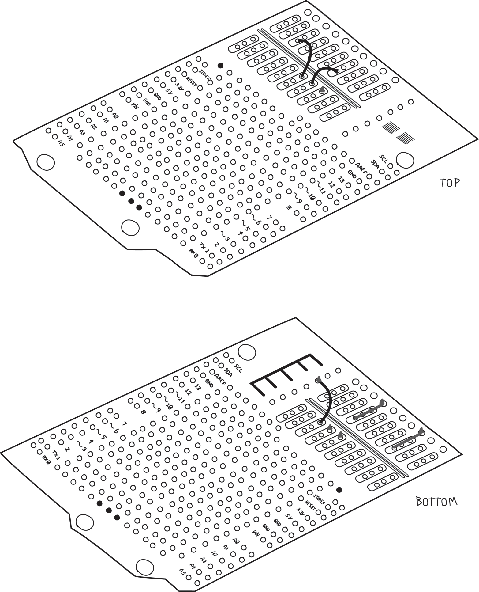
Figure 8-26. Connecting the negative screw terminals
Now connect pin 8 of each relay to the appropriate negative screw terminal, as shown in Figure 8-27.
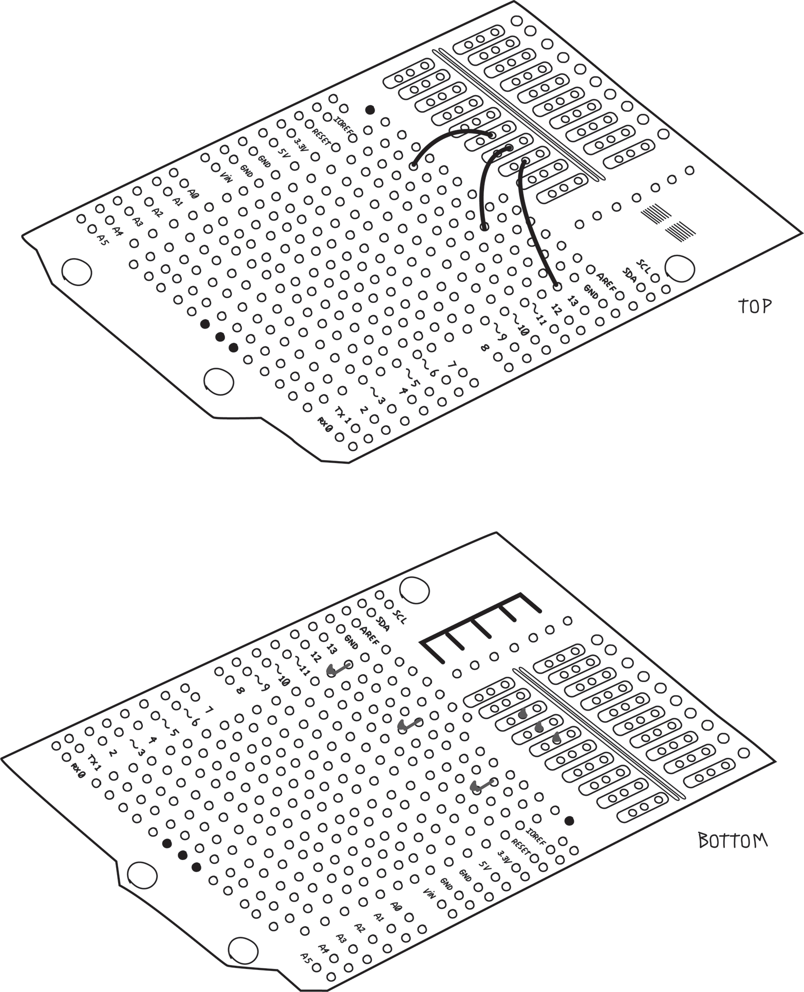
Figure 8-27. Connecting pin 8 of each relay to the appropriate negative screw terminal
Pin 4 of all the relays connect to the negative screw terminal of the water valve power supply. This is done with two wires on the top and one on the bottom, as shown in Figure 8-28.

Figure 8-28. Connect pin 4 of all the relays to the water valve power supply’s negative screw terminal
Next, connect the Arduino digital pins to the MOSFET gates, as shown in Figure 8-29. Remember the holes next to the Arduino pins are already connected to the Arduino pins so you don’t need to bend the wire and solder it directly to the pin.
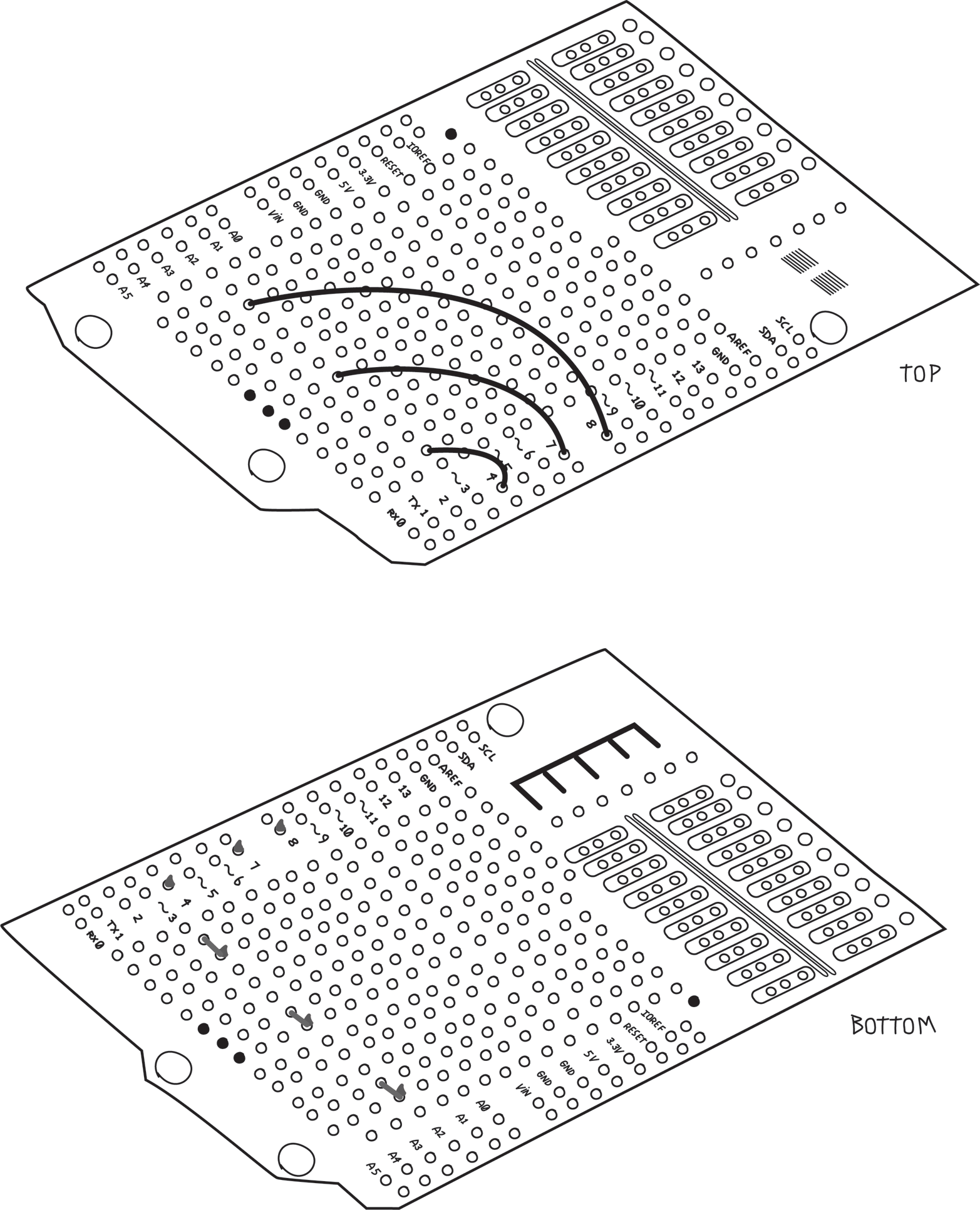
Figure 8-29. Connecting the Arduino pins to the MOSFET gates
Finally, add the two sockets: one for the RTC and one for the DHT11, and connect them to the appropriate Arduino pins. Don’t forget the 10K ohm resistor that the DHT11 needs, as shown in Figure 8-30. I’ve also taken this opportunity to connect the ground bus we created earlier to the Arduino GND pin.
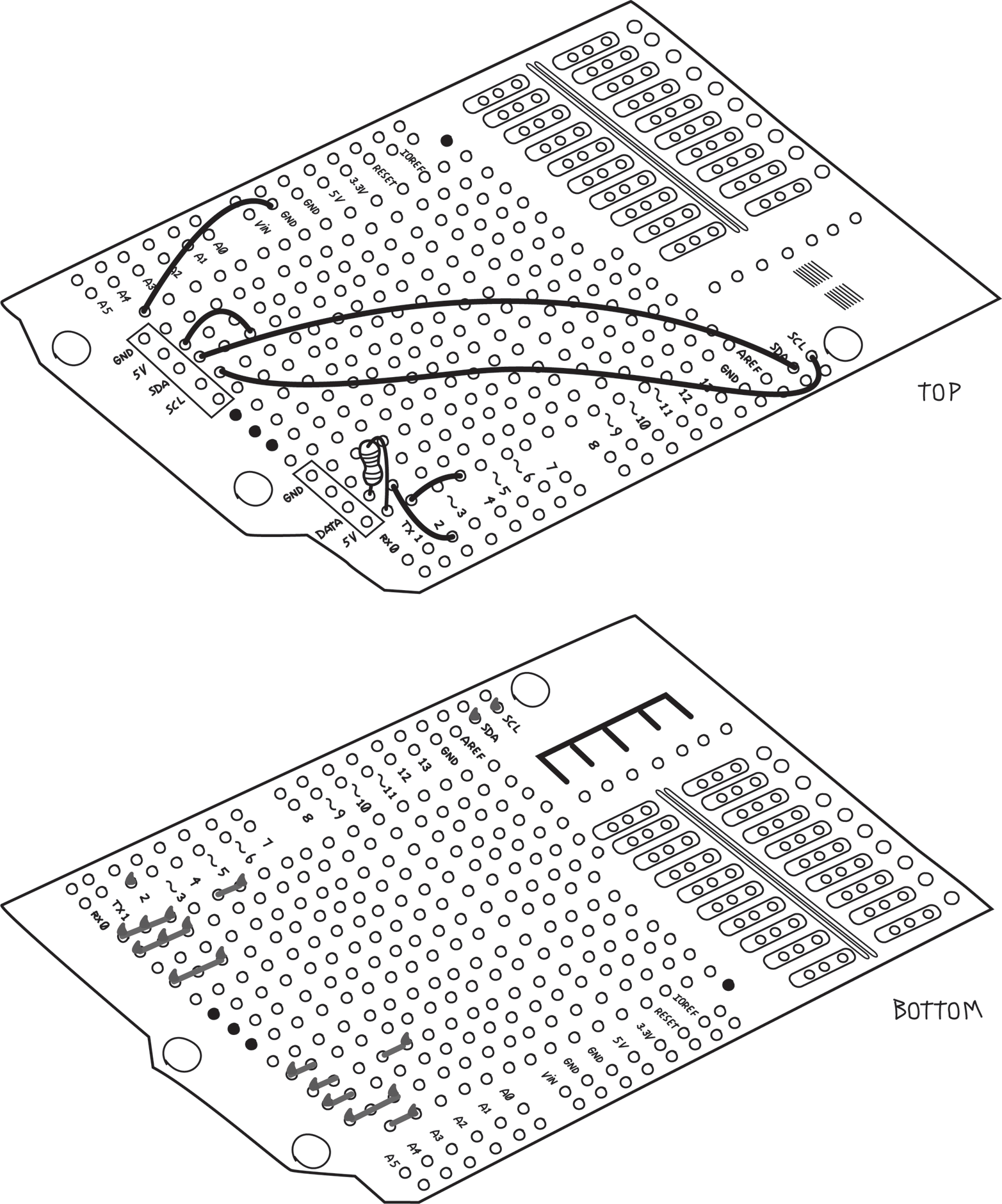
Figure 8-30. Connecting the RTC and DHT11 headers to the Arduino pins
Document which pins do what on the sockets, so that you can plug in the RTC and the DHT11 properly (an ultrafine Sharpie is handy for this).
The last step is to solder in the male or pass-through headers that will fit into the Arduino pins. This should be done last because the headers get in the way of the work you are doing on the bottom of the shield. Although you don’t need all the pins, it’s wise to put them all in for mechanical strength and possible future enhancements.
Don’t forget that the male pins should point down; that is, towards the Arduino, as shown in Figure 8-34. Make sure the pins are straight so that they will fit into the sockets on your Arduino.
Testing Your Assembled Proto Shield
First test your shield without the valves or valve power supply. Plug the shield into your Arduino. Make sure the male header on the shield goes into the correct Arduino pins. Look between the two and make sure that no connections from the bottom of the shield are touching anything on the Arduino. If they are, you’ll need to put some insulating electrical tape to prevent that from happening.
Connect your Arduino to a USB port on your computer and look for the Arduino ON LED. If it’s off, it means that you have a short circuit, and that your computer has protected itself by turning off the USB port. Unplug the USB cable and find the problem before going further.
Next you can plug in and test the relays. Remember that they are polarized and that the stripe indicates pins 8 and 9. Upload the Blink example, each time testing a different relay. Test the relays one at a time to verify that each is working.
Next we’ll test the water valve power supply and indicator LED. We’ll do the valves last.
Connect the water valve power supply to the proper screw terminals. If the water valve system is a DC system, pay careful attention to the polarity.
Again upload the Blink example and test each relay in turn. This time, the appropriate LED should come on.
Now add the valves and check them, again using Blink for each valve.
Next let’s check the RTC and the DHT11. Plug in the RTC to the header, making sure the RTC pins are in the right place. Use the RTC example to test.
Before you test the DHT11 sensor, add the long wires that will reach outdoors. Use the same colour wires as you did on the shield for consistency. Use stranded wires for this part because stranded wire is more flexible (Figure 8-31). For a more professional look, slip six short pieces of heat shrink tubing over the wires (two on each wire) before you solder. After you solder the wires to the headers and sensor, slide the tubing over the solder joints and shrink the tubing to hold it in place. I like to use clear tubing so that I can see if a solder joint breaks, and the clear tubing seems to be more in the spirit of “open”.
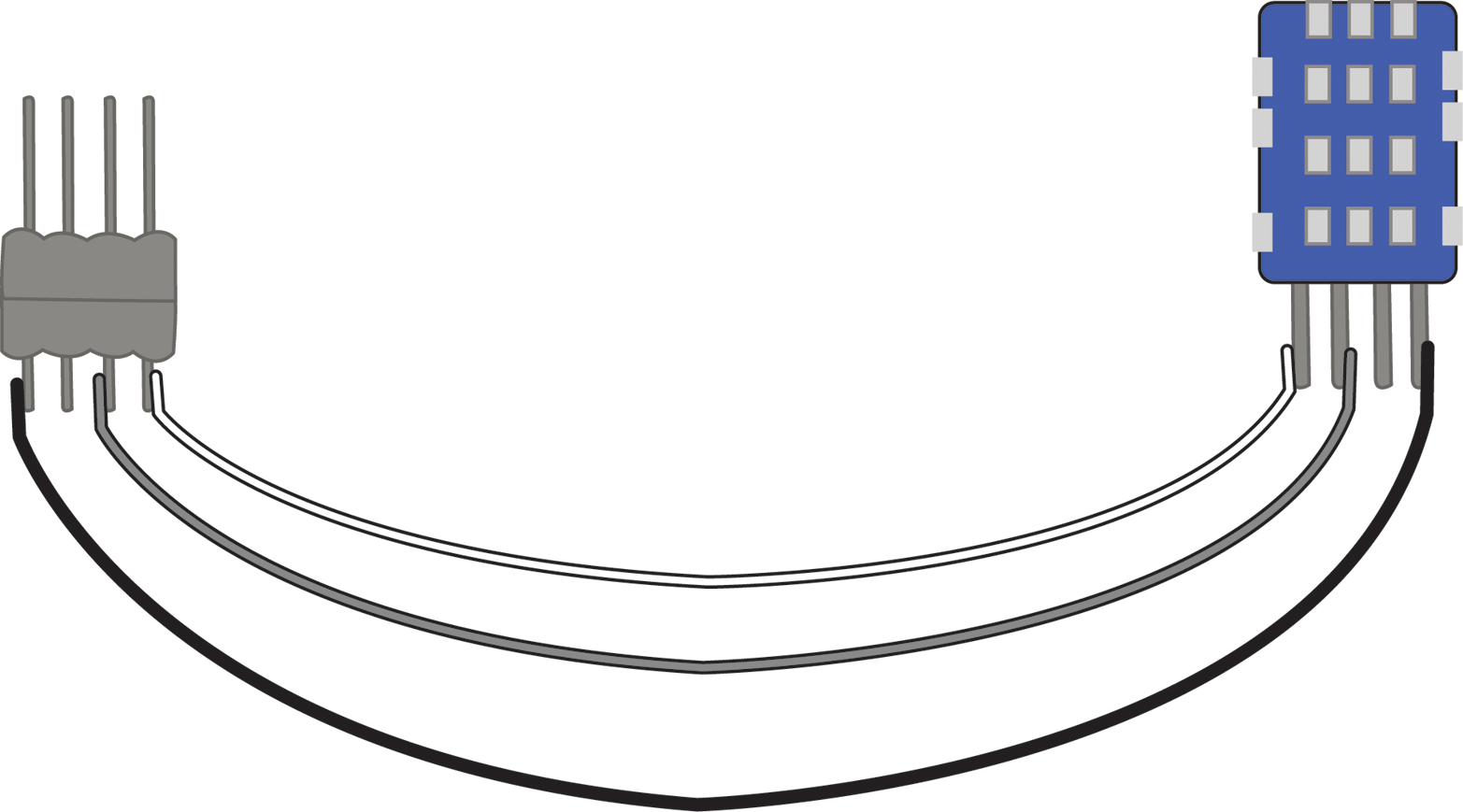
Figure 8-31. Adding long stranded wires and a male header to the DHT11 sensor
Warning
Solid-core wire should be used only in places where it will never move, i.e., when both ends are soldered to the same board.
Stranded wire should always be used between things that move relative to each other, such as between boards, or from a board to a connector.
I have seen many projects fail due to broken solid core wires that were moved too often.
Plug the male header from the DHT11 sensor into the corresponding female header, again paying careful attention to getting the right pins in the right place. Test using the DHT test example.
Assembling Your Project into a Case
Now we need to consider mounting the project in a case. Your best bet is a case that is not too deep to allow easy access, and lay everything out with a bit of room around them. Remember that the Arduino has a shield on top of it, and perhaps the RTC is standing vertically, adding to its height. The Arduino should be mounted on little feet called standoffs. A screw holds the Arduino to the standoff, and another screw from the back of the case will hold the standoff to the case, as shown in Figure 8-32.
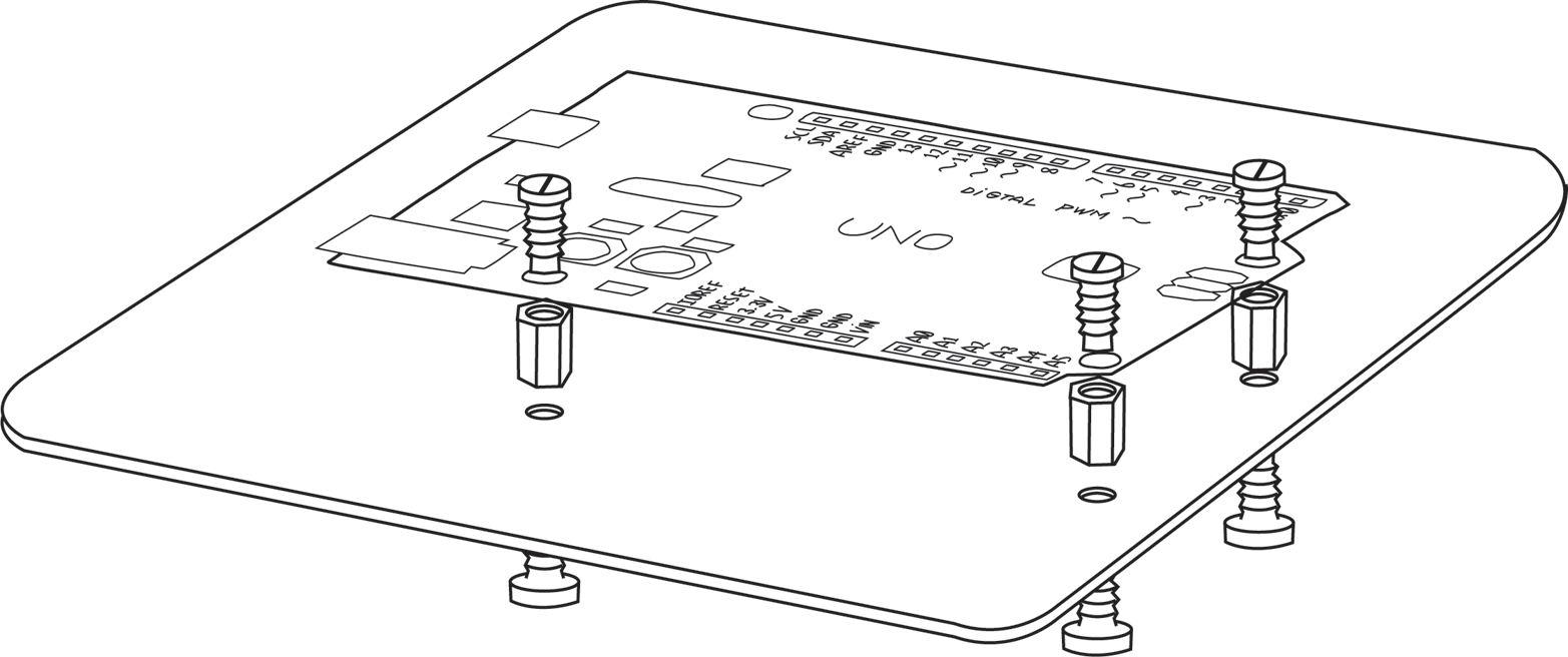
Figure 8-32. Arduino mounted on standoffs inside case
Always plan for a bigger case than you think you’ll need. Don’t forget the power supplies and connectors, and remember that wires take up space as well. You want to route the wires between the boards and not over the boards so they don’t interfere if you have to work on or remove anything. For tidy wiring, I like these self-adhesive mounts for cable ties, as shown in Figure 8-33.
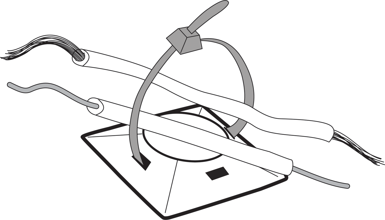
Figure 8-33. Self-adhesive cable-tie mount with wires
For projects with multiple power supplies, as we have here, consider mounting a small outlet strip inside the case. Use a strong double-sided tape to mount the outlet strip. If both your power supplies have only two prongs, you can use a two-pronged extension with at least two outlets instead of a larger three-pronged outlet strip.
This means another revision to our shopping list (we’re now at revision 0.6):
-
Case
-
Standoffs
-
Mounting screws and/or nuts
-
Cable ties
-
Adhesive cable-tie mounts (available from Jameco)
-
Strong double-sided tape (e.g., Digi-Key part number 3539-B831141-ND)
-
Outlet strip
I like to keep the power supplies away from the Arduino. You should mount the Arduino near the bottom so that the wires from the valves and the DHT11 sensor can enter from the bottom, but not too close. You’ll be happy to have room for your hands and a screwdriver when attaching wires to the screw terminals, or if you need to work on the Arduino.
The USB cable can come out of any side.
You should always try to route the wires in straight lines and in tidy bundles. This makes working on the project later so much easier.
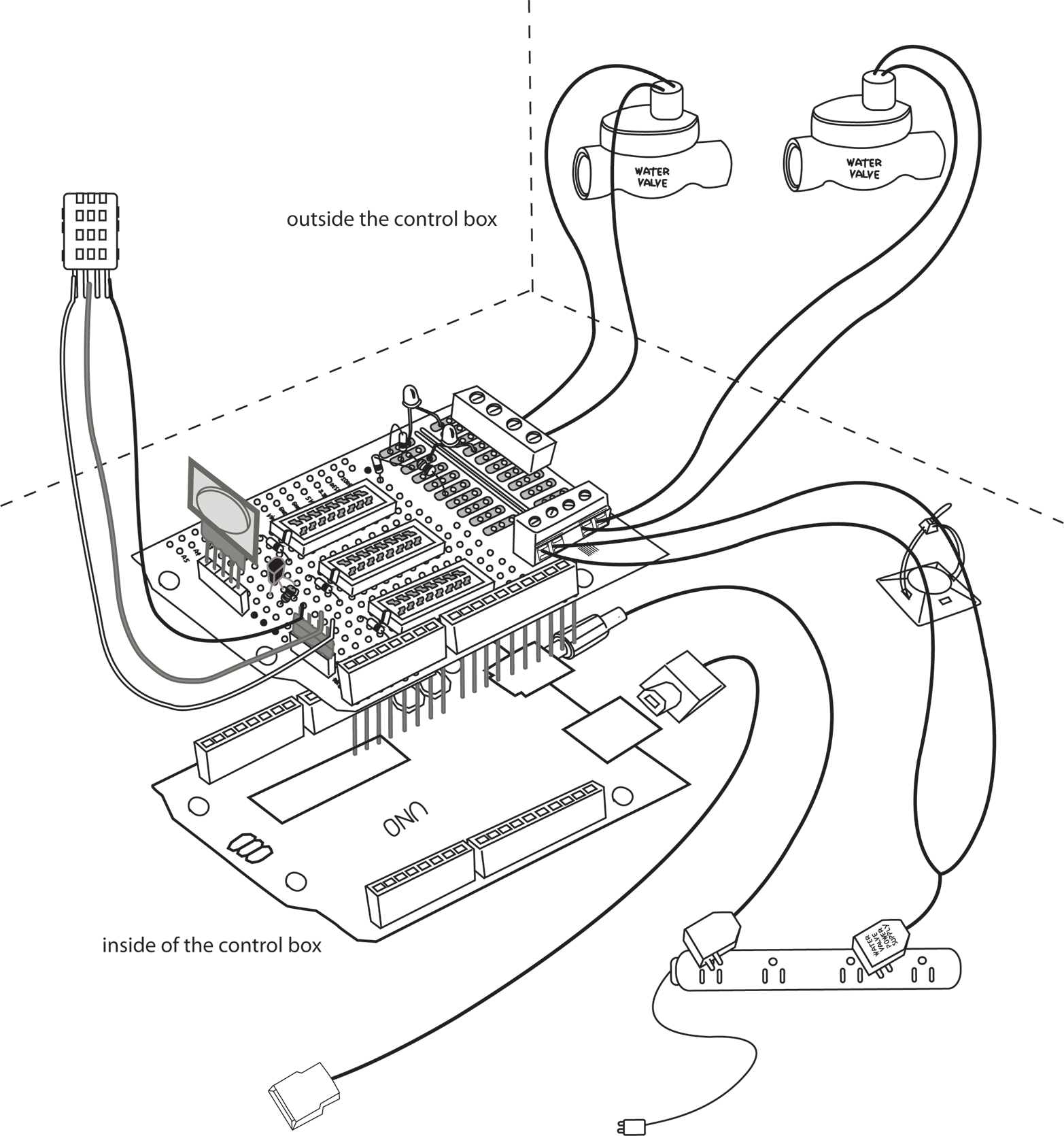
Figure 8-34. Completed automatic garden-irrigation system
In this figure I’ve left many components off the Proto Shield to make it easier to see how things are connected. I’ve shown one cable tie, but you should use as many cable ties as you need to keep the wiring organized and tidy. Always use a cable tie before a wire leaves the enclosure; this serves as strain reliever in case the cable gets tugged: it will stress the cable-tie mount, and not your delicate circuitry.
As before, pay careful attention to the polarity of the water valve power supply, if it’s a DC system.
Testing the Finished Automatic Garden Irrigation System
Note
Always test your projects in modules individually at first, in whatever way the project allows you to do this.Start by testing the Arduino and Proto Shield without the two power supplies connected. This means that your computer is providing power to the Arduino. As before, use the Blink example to test each digital output. The LEDs won’t light without the water valve power supply, but you should hear the relay clicking. Use DHTtester to test the DHT11 sensor, and the ds1307 example to test the RTC.
This might seem like you’re duplicating the tests you made after you assembled the Proto Shield, but there is a reason for this: before going on, you want to make sure that none of the work you’ve done has affected what worked before.
Now plug in the Arduino power supply and unplug your laptop to make sure your Arduino is getting powered without your laptop. Leave one of the relays clicking (using the Blink example) so that you can hear that your Arduino is still running the sketch.
Finally, connect the water valve power supply, upload the real program, and test the valves as you did earlier, by setting three different times in the near future. Check that each LED comes at the appropriate time, and that the water valves open and water flows.
Now relax in your garden and enjoy a well-deserved rest. You’ve accomplished a lot!
Congratulations! That was a complicated project! Take some pictures of your project, brag about it on Facebook, and submit it to the Arduino blog.
Things to Try on Your Own
This is a complex project with many different components. There are endless things you can do differently. Here are a few suggestions:
-
Modify the program to allow turning the water on and off at multiple times in one day.
-
Add the day of the week, and allow for different schedules on different days of the week.
-
Add an LED indicating that no ON and OFF times have been set. Turn this LED on upon reset, and turn it off the first time a time is set. This is useful in case your Arduino loses power and resets, in which case it will forget any ON and OFF settings you made.
-
Add a small LCD display to report the current time and settings
-
A more advanced exercise: The RTC module we used has a tiny memory chip in it as well that will not forget when it loses power. You can research how to use this, and save the valve ON and OFF settings into that memory, so that in case the Arduino resets, you will still have the settings.
Irrigation Project Shopping List
For your convenience, here is the final shopping list, with links:
-
Three electric water valves
-
Three sockets for relays
-
Three 1K resistors for LEDs
-
Three MOSFETs to control the relays, 2N7000, 10-pack
-
Six diodes, 1N4148 or equivalent, 25-pack
-
Three relays (e.g., DS2E-S-DC5V, such as Digi-Key part number 255-1062-ND)
-
Four dual-screw terminals (e.g., Jameco part no. 1299761)
-
Case: make your own or use a plastic storage bin (e.g., a Sterilite or a fancy metal box (available from Automation 4 Less)
-
Cable ties
-
Strong double-sided tape (e.g., Digi-Key part number M9828-ND)
-
Outlet strip or extension cord with at least two outlets