
Chapter 4. First Steps with Digital Electronics

Development platforms like the BeagleBone provide an environment for a wonderful hybrid of both software and hardware hacking. In this chapter, you’re going to test drive the General Purpose Input/Output pins (GPIO) on the board to get a basic sense of how they work and how you can read from and write to them.
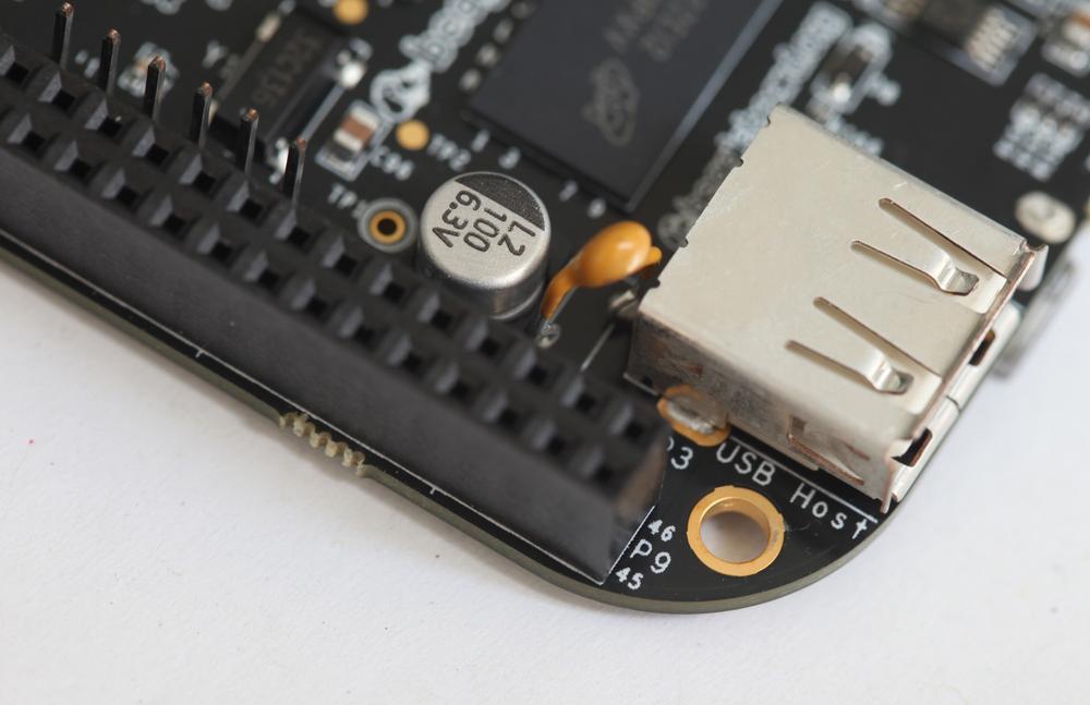
No doubt you’ve noticed the two sets of headers that run along the edges of the board. They’re labeled P8 (Figure 4-1) and P9. Each header has 46 pins and if you look closely you can see that pins 1, 2, 45, and 46 are labeled on each header (Figure 4-2). To identify pin numbers in the middle, you’ll have to count off from the pins on the end.

The pins have many different possible functions, from controlling LCD screens, reading sensors, communicating with other electronics, and much more. Most pins can even be switched between modes to accommodate different possible functions. See Getting Things All Muxed Up for more information.
In this chapter, we’re going to use a few of the pins in their GPIO mode. GPIO pins have two states: high and low. When a pin is high, that means it’s connected to 3.3 volts. When a pin is low, it means that it’s connected to ground. It’s important to remember that digital pins must be either high or low. Reading the state of a pin that’s not connected to anything will return unpredictable results. We say such a pin is floating.
Warning
3.3 volts is the specified logic level of the BeagleBone. Other platforms, like the Arduino, may use 5 volts. Use only 3.3 volt logic components with the BeagleBone. Otherwise you can permanently damage the board.
Before we get into writing any software, let’s take a look at how to do some basic digital pin control from the Linux command line. Once you get to know how the Linux kernel uses a virtual filesystem to read and write pins, it makes programming the BeagleBone much easier. It also means that you can then use any programming language you’re comfortable with to read and write to the pins. As long as you can read and write files, you can work with GPIO.
To walk through the tutorials this chapter, you’ll need the following components in addition to your BeagleBone, its power supply, and your computer:
- Solderless breadboard
- Jumper wires
- LEDs
- Resistors: 1×100 ohm, 1×10K ohm
- Momentary pushbutton or toggle switch
Connect an LED
A great way to get to know a new platform is simply getting an LED to blink, so let’s start by wiring up an LED:
- Shut down the BeagleBone (see Shutting Down). It’s always good idea to shutdown the board and remove power before you start wiring things up to the pins.
- Using a jumper wire, connect the negative rail of the breadboard to one of the BeagleBone’s ground pins, which are located on pin one and two of header P8 and P9.
Using another jumper wire, connect the breadboard’s positive rail to the BeagleBone’s 3.3 volt source which are pins 3 or 4 on header P9.
Warning
Be very careful not to accidentally connect the rail to the 5 volt source on pins 5 and 6. The GPIO pins can only handle 3.3 volts.
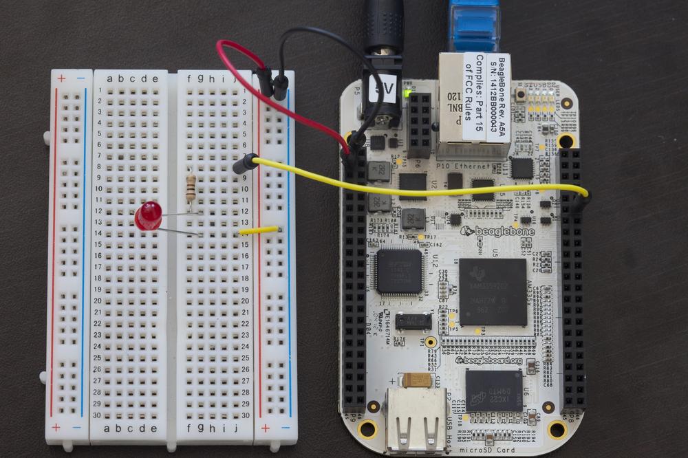
- Place an LED in the breadboard so that the cathode side (the shorter wire) is connected to the negative rail and the anode side is in one of the rows of the breadboard.
- Using a 100 ohm resistor, connect the anode side of the LED to another row on the breadboard.
- Connect the other side of the 100 ohm resistor to pin 12 on header P8. On a 100 ohm resistor, the color bands printed on it will be brown, black, brown, and then gold or silver. Your circuit should look like Figure 4-3.
Getting Things All Muxed Up
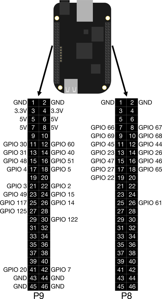
You may have noticed that we’ve only labeled a few pins in Figure 4-4 and here’s why: many pins can be assigned different functions, not just digital input and output. This feature is known as pin multiplexing or “pin muxing” and it can make things a little tricky. For this tutorial, I’m using pins that default to GPIO mode when the BeagleBone is powered on. Many of the pins default to other modes. Keep in mind that the defaults can also change as updated versions of Linux are released for the board.
Output
Referring to Figure 4-4, you know to use GPIO signal 44 within Linux for pin 12 on header P8 and you know that it’s set to work in GPIO mode by default. With that knowledge, you’re ready to use the command line to control that pin:
On the command line, change to the
gpiodirectory:root@beaglebone:~#
cd /sys/class/gpioNote
When you’re typing out long paths on the command line, there’s a feature called command-line completion that will save you a lot of time. Start typing the first few letters of the directory or file and then hit tab key. If the system has a single file or directory that matches that, it will fill in the rest of the name for you. If there’s no file or directory or there are multiple items that start with the same letters, you’ll get a beep.
When you list the contents of the directory with the command
lsyou’ll notice there’s no folder for gpio signal 44. That’s because we need to export the pin to userspace so that we can control it. To do that, use theechocommand to write the number 44 to theexportfile:root@beaglebone:/sys/class/gpio#
echo 44 > exportNote
These pins can be used by many different possible functions and you don’t want them to conflict with each other. For example, if you attach a BeagleBone expansion board, or cape, it may request access to a few of these pins for itself. Exporting the pin to the userspace is a way of saying to the Linux kernel, “I, the user, want to use this pin.” The kernel will then warn you if it’s already in use. If it’s not in use, it will create the appropriate directory so that you can control the pin and it will then warn others that you have control of it.
Now when you type
ls, you’ll see the newly createdgpio44directory.root@beaglebone:/sys/class/gpio#
lsexport gpio44 gpiochip0 gpiochip32 gpiochip64 gpiochip96 unexport
Change to that directory:
root@beaglebone:/sys/class/gpio#
cd gpio44Since you want to control an LED, you need to set the pin as an output by writing the word “out” to pin 44’s
directionfile:root@beaglebone:/sys/class/gpio/gpio44#
echo out > directionNow we’re ready to set the pin high to illuminate the LED. Write 1 to the
valuefile:root@beaglebone:/sys/class/gpio/gpio44#
echo 1 > valueWe can then set the pin low and turn off the LED by writing a 0 to the
valuefile:root@beaglebone:/sys/class/gpio/gpio44#
echo 0 > value
If you saw the LED illuminate after writing 1 to its value file and it turned off when you wrote 0 to the value file, congratulations! Feel free to experiment with the other pins in Figure 4-4.
Input
If you can control an output pin by writing to the value file, it stands to reason that you can read an input pin by reading the value file. By doing this, you can check the state of physical buttons and switches. Let’s try it out now:
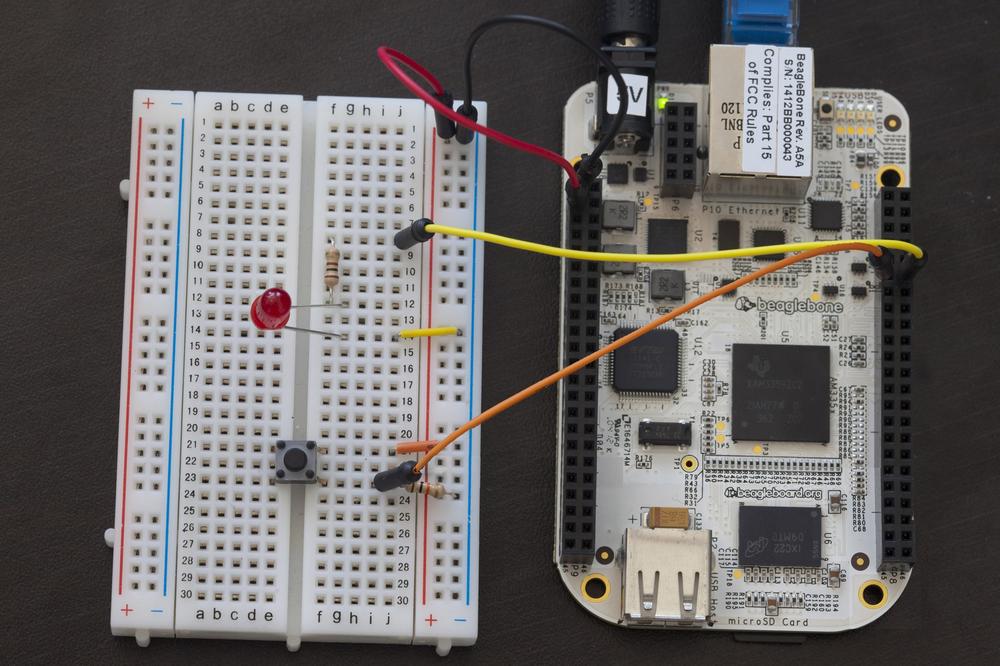
- Place a push button into the breadboard so that it straddles the center channel. If you don’t have a button handy, you can also use a toggle switch.
- Connect one lead of the button to the positive rail.
- Connect the other lead of the button to the input pin 11 on header P8. (See Figure 4-5 of BeagleBone wired up.)
- Connect a 10K pulldown resistor from the ground rail to the button lead that connects to the input pin.
Note
Remember that GPIO pins must be either high or low. That is to say, connected to either 3.3 volts or ground. The 10K pulldown resistor in the step above ensures that when the button is not pressed and the connection between 3.3 volts and the input pin is broken, the input pin is then connected to ground through the 10K resistor. Using a resistor ensures that when the switch is closed, the 3.3 volts (which is inclined to follow the path of least resistance) doesn’t go directly to ground, creating a short circuit. Instead, it goes to the input pin.
Let’s get back to the command line now. First, export the pin to the userspace and change to its directory. According to Figure 4-4, pin 11 on header P8 is GPIO signal 45, so that’s what we’ll export.
root@beaglebone:/sys/class/gpio/gpio44#
cd ..root@beaglebone:/sys/class/gpio#echo 45 > exportroot@beaglebone:/sys/class/gpio#cd gpio45Set the pin direction as an input:
root@beaglebone:/sys/class/gpio/gpio45#
echo in > direction
Now, instead of writing the
valuefile, we’ll read it using the commandcat:root@beaglebone:/sys/class/gpio/gpio45#
cat value0This should return 0 for low. This means that the pin is connected to ground. Now press and hold the button while you execute the
cat valuecommand again. If you have the button wired up correctly, you should now see a 1, indicating the pin is high (connected to 3.3 volts).Note
An easy way to execute a command again is to hit the up arrow key on your keyboard and then hit enter. You can keep hitting up to scroll back through your history of commands. Just hit enter when you get to the command you want.
When you’re done with the pins, be sure to unexport them from the userspace:
root@beaglebone:/sys/class/gpio/gpio45#
echo 44 > /sys/class/gpio/unexportroot@beaglebone:/sys/class/gpio/gpio45#echo 45 > /sys/class/gpio/unexport
If you’ve successfully blinked an LED and read a button from the Linux command line, congratulations! It may seem trivial, but these examples represent the very basic foundation of digital electronics with the BeagleBone. And you’re not limited to only LEDs, buttons, and switches. With the right circuitry, these could easily become tilt sensors, blenders, door security sensors, buzzers, motors, and much more.
Project: Networked Outlet Timer
Now that you know how to read and write pins from the command line, you can bring some of Linux’s powerful features into the physical world. This project uses Linux’s job scheduler, cron, and a PowerSwitch Tail relay to let you control a lamp or other A/C device on a set schedule. And since the BeagleBone is already network-enabled, it lets you change the settings of your outlet timer from the comfort of our computer, or even from the other side of the globe.
This project will also demonstrate the basics of using shell scripting as one method to programmatically execute commands.
Note
If you haven’t picked up a PowerSwitch Tail yet, you can test this project out using the LED you’ve already got connected to your BeagleBone. If you wired the LED up as directed earlier in this chapter, you won’t even need to rewire anything.
Parts
Here’s what you’ll need to try this project out:
- BeagleBone
- 5V DC power supply
- Ethernet cable
- PowerSwitch Tail II
- Hookup wire
- Lamp
Wire up the Circuit
- Using the hookup wire, connect pin 1 from the PowerSwitch Tail to pin 12 on header P8 on the BeagleBone.
- Using another strand of hookup wire, connect pin 2 from the PowerSwitch Tail to one of the ground pins on the BeagleBone. On both headers, they’re on pins 1 and 2.
- Plug the PowerSwitch Tail into a power source and plug your lamp into the other end of the PowerSwitch Tail.
- Be sure the lamp is switched on. It won’t light up yet since the PowerSwitch tail is currently interrupting the power between the lamp and your power source.
Note
The PowerSwitch Tail is a high voltage relay circuit that has been packaged up for easy use. It lets you use the 3.3 volt logic level signals that come from the BeagleBone to flip a switch to connect the A/C power to the device that’s connected to it. So writing pin 12 to high will close the switch between the A/C wall outlet and our lamp.
Test the Circuit
Execute the following commands to actuate the relay and turn the lamp on. They should look familiar since they’re the same commands we used to light the LED earlier in this chapter.
root@beaglebone:~#
echo 44 > /sys/class/gpio/exportroot@beaglebone:~#echo out > /sys/class/gpio/gpio44/directionroot@beaglebone:~#echo 1 > /sys/class/gpio/gpio44/valueIf the lamp turns on, you know you’ve got the circuit right. Otherwise, check that the lamp is switched on, that you’ve got the PowerSwitch Tail wired up correctly, and that you typed the commands correctly.
Note
If you received the error “write error: Device or resource busy”, then you probably forgot to unexport pin 44 as directed at the end of Input. Make sure you run the
unexportcommands shown there before you try this example.Now unexport the pin.
root@beaglebone:~#
echo 44 > /sys/class/gpio/unexport
Create the Shell Scripts
You can use a shell script to execute batches of commands. While shell scripts have the potential to be powerful and complex, they can also be very basic and as easy to write as entering the commands onto the command line.
Use
cdto change to your home directory (remember that the shorthand for the home directory is~) and create a new file calledlightOn.shfor the shell script:root@beaglebone:~#
cd ~root@beaglebone:~#nano lightOn.shThis will launch the nano text editor. Type in the following code:
#!/bin/bash
echo44 > /sys/class/gpio/export
echoout > /sys/class/gpio/gpio44/direction
echo1 > /sys/class/gpio/gpio44/value
-
This line is required for all shell scripts
-
Export pin 44
-
Set the direction to output
-
Set the pin high
Note
For editing files while in a text-based environment there are plenty of options like vi, emacs, and pico. At risk of getting into a debate about which text editor is best, I’ll say that I prefer using nano, but feel free to use whatever text editor you’d like. If you’re new to this environment, start off with nano, which is arguably the easiest editor to use.
- Type Control-X and type “y” to save the file when it prompts you.
Use nano to create another file called
lightOff.shwith the following code:#!/bin/bashecho0 > /sys/class/gpio/gpio44/value
echo44 > /sys/class/gpio/unexport-
Set the pin low
-
Unexport the pin
- Type Control-X and type “y” to save the file when it prompts you.
To make both of those scripts executable, execute the following commands:
root@beaglebone:~#
chmod +x lightOn.shroot@beaglebone:~#chmod +x lightOff.sh-
Now when you type
./lightOn.sh, the light should turn on. When you type./lightOff.sh, the light should turn off. (You will need to be in the home directory to do this.)
Scheduling the Scripts
We’re going to use Linux’s built-in scheduler, cron, to set the light to turn on at 7pm and turn off at 4am.
On the command line, type the following command to edit your crontab (cron settings table) within nano (the
EDITOR=nanopart of the command forcescrontabto use the nano editor instead of the system default, which is usually vi):root@beaglebone:~#
EDITOR=nano crontab -eAdd the following lines to the end of the file:
0 19 * * * /root/lightOn.sh
0 4 * * * /root/lightOff.sh
- Type Control-X and type “y” to save the file when it prompts you.
- If the current time is between 7pm and 4am, you’ll need to execute the lightOn.sh manually so that lightOff.sh doesn’t return an error when it’s executed at 4am.
A Crash Course in Cron
The formatting for the crontab might seem a little cryptic at first, but it’s not as confusing as it seems. The cron scheduler will allow you to execute commands as frequently as once a minute or you can even set a command to execute many years in the future. Each crontab entry is on its own line with 5 space-delimited settings (sometimes 6, in the case of specifying years) followed by another space and then the command that should be executed as you can see in Table 4-1.
| 0 | 19 | * | * | * | /root/lightOn.sh |
Minute (:00) | Hour (7pm) | Every Day | Every Month | Every Day of Week | path to command |
Let’s say you want a command to be executed every five minutes. See Table 4-2 for what the entry would look like.
| */5 | * | * | * | * | /root/blinkLED.sh |
Every Five Minutes | Every Hour | Every Day | Every Month | Every Day of Week | path to command |
And if you want a command to be executed twice a week, on Monday and Thursday, see Table 4-3 for what the entry would look like.
| 0 | 8 | * | * | MON,THU | /root/takeOutTrash.sh |
Minute :00 | Hour (8am) | Every Day | Every Month | Monday and Thursday | path to command |
To execute a command on a particular year, you can add another space-delimited setting after the day of the week to specify the year (or years).
If you want to adjust the timing of the lamp, all you have to do is log into your BeagleBone and edit your crontab. You could even set up your router so that it’s accessible from outside your home network, just be sure to set a password! In Chapter 6, we’ll dig into Internet-connected projects even more.