
Chapter 3. Introduction to Arduino
The maker movement, coined the “New Industrial Revolution,” is taking the world by storm. Creating new electronics is no longer limited to high-tech laboratories and corporate funding; it’s been brought directly into people’s lives and homes via cheap electronic components, testbeds, and widely supported community spaces. It’s high-school shop class meets the electronics industry at a million miles per hour, and a lot of it is the result of one simple idea: the Arduino.
What is Arduino
Arduino is a paired hardware and software platform that enables rapid design, prototyping, and building of devices that can sense and control aspects of the physical world. The hardware behind Arduino is an open source physical computing platform based on a simple Atmel microcontroller. A microcontroller is a small computer with its own core, memory, and periperals, including inputs and ouputs (I/Os), and USB connections. The software that controls the Arduino hardware is written to the board through an integrated development environment (IDE). The IDE makes it easy to program Arduino not only because it connects to the board, but also because it comes with a wealth of examples and preprogrammed functionality.
Materials List
This chapter, along with Chapter 4, requires the most parts in the book. They are listed below as well as in Appendix A. An alternative to buying the first six items in this list separately is to purchase an Arduino-style starter pack, such as the SunFounder Sidekick Basic Starter Kit. Just make sure that the one you purchase contains all of the first six items (down to potentiometer):
- A breadboard
-
Although any solderless breadboard will do, it’s nice to buy one with power rails on the sides (see “The Blink Circuit” for further explanation). For all the exercises in this chapter, a half-size breadboard will give you more than enough area to work with. These can be purchased for a few dollars on Amazon. You can also purchase them from Adafruit, but they’re slightly more expensive at $5.
- Male-to-male breadboard wires
-
Used for connecting Edison’s pins to your breadboard; make sure you buy male to male (M/M). These are probably cheapest on Amazon. Adafruit also sells packs in two different flavors: regular in mixed lengths and premium in just one length. The range in price is $6-$8.
- An LED
-
To complete the exercises in this chapter, you really only need a single bare LED, but it’s almost impossible to buy an LED as an individual unit. That’s OK! LEDs are super useful for all manner of experiments. Adafruit has heaps of them, and you’re looking specifically for ones like this, a bare breadboard LED in a single color. You can also buy mixed packs on Amazon.
- Resistors
-
A pack of resistors with any value from 220 ohms to 1 kohms will work for this book. However, if you’re thinking about getting more seriously into building and making, try getting a mixed pack in a large range, such as the E-Projects - 400 Piece, 16 Value Resistor Kit.
- A button
-
The cheapest and easiest are sold as a pack on Adafruit for under $3. However, button choices are fairly limitless, and you can buy some really cool ones if you’re so inclined.
- A potentiometer
-
You can buy a single potentiometer from Adafruit for under $2.
- An accelerometer
-
The specific accelerometer chip you’ll be using in this chapter is the MMA8451 sold for under $10 on Adafruit. Accelerometers are one of the most widely used and basic sensors for embedded devices, which is why I chose it to pair with Edison.
- A SPI-driven display
-
Any screen that uses ILI9341 will work with the exercises in this book. You can find some cheap ones on eBay and Newegg, but I personally recommend the resistive touch shield (more on why in “SPI Screen”) or the resistive touch breakout.
The Arduino IDE
The Arduino IDE is the conduit to programming your Arduino board. It makes it easy to write code and upload it to the board, and runs on Windows, Mac OS X, and Linux. Like everything Arduino, the IDE is open source.
Installing
Intel Edison is an Arduino-compatible device, meaning it’s not an Arduino but can be used almost identically as one. Edison uses an Intel Quark microcontroller to drive the I/Os on the Edison board. When originally released, Edison required a separate IDE than Arduino boards. Since then, both the Intel and Arduino folks have gone to great lengths to integrate the functionality of both into one IDE. From version 1.6 onward, the IDE distributed by Intel and Arduino will work with both platforms.
If your host computer is a Linux machine or you skipped straight to flashing your Edison with the Phone Flash Tool in Chapter 1, then you need to install the Arduino IDE before continuing. To download and install this IDE, go to the Intel or Arduino download page and click the link for your host computer system. After the download completes, unpacking the file creates the IDE for your platform. If you’re on Mac or Linux, move it to a convenient location on your host computer. For instance, on a Mac, you might want to place it in the Applications folder. Double-click the IDE to start it.
Otherwise, the IDE is already installed on your computer. Locate it and open the program.
Navigating the IDE
The Arduino IDE is shown in Figure 3-1. The IDE is broken into several regions, the most important of which is the large white space that contains your code, also known as a sketch.

Figure 3-1. The Arduino IDE for Intel Edison
To the top-left of the sketch window are five light-green buttons. From left to right, they are:
- Verify
-
Saves your sketch and checks it for errors
- Upload
-
Verifies your code, transfers it to Intel Edison, and runs it on the board
- New
-
Creates a new IDE window with a blank sketch
- Open
-
Opens an existing sketch
- Save
-
Saves the current sketch
Keyboard Shortcuts
The preceeding commands also have some useful keyboard shortcuts:
-
Ctrl+U or Cmd+U: Upload
-
Ctrl+R or Cmd+R: Verify
-
Ctrl+S or Cmd+S: Save
-
Ctrl+N or Cmd+N: New
-
Ctrl+O or Cmd+O: Open
Below the white sketch portion is a green horizontal status bar that indicates the state of the IDE, and a black message window that gives a more complete set of information about past and present status. Both of these portions of the IDE should be blank. If you click the Upload button at the top, you’ll notice that they become populated with information.
Finally, the communications port that the IDE is using to transmit information to and from your Intel Edison is shown in the bottom-right corner.
Before you begin programming, you need to configure your IDE to communicate properly with our Edison. This means selecting the proper board and communications port.
To select your Edison, open the Tools drop-down, select Board, and then Intel Edison. To select your communications port, open the Tools drop-down, select Port, and then the port of the form /dev/cu.usbmodemXXXX for Mac or COMXX for Windows. One of the easiest ways to find which port belongs to your Edison is check the available ports with Edison unplugged and then plug it in and choose the new port that wasn’t there before.
Sketches and Functions
Every Arduino sketch requires two functions: setup and loop. A function is a self-contained piece of code that runs independently of the rest of the program. The setup function runs exactly one time when the program starts. After the setup function completes, the loop function runs over and over again so long as Edison is powered. Think about it like going for a run. The setup function is like putting on your running shoes: you do this exactly one time at the beginning of your run. The loop function is like the run itself: you take step after step after step until your run completes and you “power down.”
Arduino is based on the programming language C++. In C++, you define your functions with the same structure every time:
return_typefunction_name(inputvariableshere){//Code here}
The first word of your function states the type of output or return from that function. Because the setup function does not return any output, it has the return type void. The second word is the name of the function and can be made up of any combination of alphanumeric characters and the underscore (_), so long as the first character is not a number. The input variables follow the function name. They are surrounded by parenthesis and separated by commas. For the function named setup, the parentheses are left empty since the function does not take any inputs. Finally, all code associated with a given function is placed between curly brackets. The opening curly bracket comes after the closing parenthesis around the variables, and the closing curly bracket comes after all the code is complete.
Comments
Comments are like annotation for code. They themselves are not code; they are written into code to help increase understanding and readability. There are two ways to write comments in C++:
//Single line-
Everything on this line is now a comment
/*Multi-line-
Everything is a comment until the closing symbols
*/
You see a single line comment (//Code here) in the previous code samples.
There are many native types in C++ and they’re used for declarations as well as function definition. Some of the more common types we’ll use are:
- boolean
-
binary true or false
- byte
-
an integer from 0 to 255
- char
-
an integer from -128 to 127
- unsigned char
-
same values as byte
- word
-
integer value from 0 to 65535
- unsigned int
-
same values as word
- int
-
integer value from -32768 to 32767. This is the type that is most commonly seen in Arduino examples and the type you’ll probably use the most.
- unsigned long
-
integer value from 0 to 4,294,967,295
- long
-
integer value from -2,147,483,648 to 2,147,483,647
- float
-
decimal value from -3.4028235E38 to 3.4028235E38
Digital Output with Blink
It’s easier to understand all of this through an example. Let’s start with the quintessential first microcontroller program, blink. In this example, you’ll use Edison to control the output of a light emitting diode (LED), a semiconductor device that emits light when a current passes through it. This is the simplest circuit you can control with your Edison to observe a physical output.
The Arduino IDE provides example code, and we’ll use this to get started. Open the File drop-down, then select Examples, 01.Basics, Blink. In the new window that opens, you’ll notice that the setup and loop functions are now populated with code:
// the setup function runs once when you press reset or power// the boardvoidsetup(){// initialize digital pin 13 as an output.pinMode(13,OUTPUT);}// the loop function runs over and over again forevervoidloop(){digitalWrite(13,HIGH);// turn the LED on (HIGH is// the voltage level)delay(1000);// wait for a seconddigitalWrite(13,LOW);// turn the LED off by making// the voltage LOWdelay(1000);// wait for a second}

Within the
setupfunction, we call the functionpinMode, which takes two arguments. The first argument is an integer specifying the pin number. The pin numbers are written next to each of the Arduino-compatible pins on the top of the board. The second argument tells the hardware in which mode to operate the pin: input or output. Since an LED is an output device (it outputs light), we set the pin attached to the LED to reflect this. Pin 13 is special; while it does have a slot for connecting external hardware, it’s also wired to an LED directly on the board. This is the LED that your code will make blink.
The
loopfunction issues four sequential commands that toggle the LED on and off at one-second intervals. Pin 13 is a digital pin, meaning it only takes one of two possible values:HIGHorLOW. You use thedigitalWritefunction to control the output of digital pins. When you write pin 13 toHIGH, you’re telling Edison to send a high voltage (5 volts on the Arduino breakout) signal to pin 13, lighting the LED. Conversely, when you write pin 13 to LOW, you’re telling Edison to send a zero voltage signal to pin 13, turning the LED off. In between, we use the delay function to pause the program. The argument1000tells delay to wait for 1,000 milliseconds, or 1 second. You can generate even shorter delays using thedelayMicrosecondsfunction.
Don’t Forget the SemiColon
All commands and variable declarations in C++ are terminated with a semicolon.
Upload this code. You’ll notice that an LED on the board begins to blink on and off every second. This is the on-board LED that is wired to pin 13, and you’re controlling it with your Intel Edison!
One of the aspects that makes Arduino so convenient is that functions like digitalWrite, pinMode, and delay are so common that they’ve been preprogrammed into the Arduino software environment so that you don’t have to write them yourself.
Saving Sketches
The Arduino IDE creates an Arduino folder within the Documents folder on Mac, and Arduino folder within My Documents on Windows, and a Sketchbook folder /home/username/ on Linux. By default, any sketches that you save will be saved to this directory. If you want, you can change this by editing your preferences in the Arduino IDE.
Going Further with Blink
Now you’ll expand your blink example a bit. First, you’ll define some variables to make your code read a little easier. A variable is a reference to stored information and the name is typically chosen to represent the information it contains. Declare the variable called ledPin at the top of the sketch, before the setup function. Since the ledPin number is an integer, we’ll declare it as such:
intledPin=13;
Declaring the variable in the main part of the sketch, outside of any functions, means that every piece of code within your sketch has access to it. Change the number 13 in pinMode and digitalWrite to our variable ledPin. You can also declare a variable for the delayTime and specify this in the delay function.
intdelayTime=1000;
Aside from variables making it easier to simply read what’s going on, they also make your code much more easily adaptable. Suppose you wanted to blink the LED at a cadence of every five seconds. Now all you need to do is change the variable at the top instead of adjusting the numbers all throughout your code.
Note
When you specify HIGH and LOW to digitalWrite, you’re actually using variables that have been predefined in the Arduino software. HIGH is an integer variable equal to one, and LOW is an integer variable equal to zero.
Finally, you’re going to add a function that handles the blinking. Name this function blinkIt, and since it has no return values, declare this function with void. Move the contents of loop into the function blinkIt:
voidblinkIt(){digitalWrite(ledPin,HIGH);// turn the LED on (HIGH// is the voltage level)delay(delayTime);// wait for a seconddigitalWrite(ledPin,LOW);// turn the LED off by making// the voltage LOWdelay(delayTime);// wait for a second}
Since the blinkIt function will perform all the steps it takes to make your Edison board blink, all you need to do now is call it in the loop function to run it over and over again forever:
voidloop(){blinkIt();}
Your final code should look something like this:
intledPin=13;intdelayTime=1000;voidblinkIt(){digitalWrite(ledPin,HIGH);delay(delayTime);digitalWrite(ledPin,LOW);delay(delayTime);}voidsetup(){pinMode(ledPin,OUTPUT);}voidloop(){blinkIt();}
Upload this code to your Edison, and you’ll see that your board keeps on blinking. Try playing with the delay times to see what Edison and your eyes can handle.
The Blink Circuit
Blink is not only a great introduction to Arduino programming, but also an excellent introduction to circuits. You’re now going to move your blink circuit off the board and onto a breadboard.
Circuits consist of closed loops of electrical current. The current originates at a source, such as a battery or power supply, and terminates at the return or ground. The pins on your Arduino breakout can act as both sources and returns. When the circuit loop is complete, the electrons that make up the current are returned back to the source. Any part of an electrical circuit between the source and return is called the load. The load in an electrical circuit can be pretty much anything: lights, resistors, screens, speakers, and even the wire making the connections.
Some common circuit elements, including all the ones that you’ll use in this book, are shown in Figure 3-2. The top row of Figure 3-2 shows how these common parts are often represented in drawings. The bottom row shows how these parts are commonly represented in a circuit diagram, or graphical representation of an electrical circuit.
From left to right, these elements are (a) resistors, (b) a potentiometer, (c) LEDs, and (d) pushbuttons. Ideal resistors are electronic components that have a specific, never-changing resistance to the movement of current through them. Resistors come in many different sizes, shapes, and values. You’ll notice that there are three resistors in Figure 3-2 (a). These resistors have different resistance values (220 ohms, 470 ohms, and 1 kohm) that can be read from their color codes. We’ll talk in more depth about resistors and the rest of these items later on in this chapter. For the representations of many more common components in circuit diagrams, see SparkFun’s tutorial.

Figure 3-2. Table of common circuit elements you’ll use in this book. The top row shows the pictorial representation of each part, and the bottom row shows possible circuit diagram representations.
Power Down First
Basic electrical safety requires removing power from the circuit before changing connections. This will avoid damaging your board, your components, and (most importantly) yourself.
For your blink circuit, you’ll need some jumper wires, a single color LED, a resistor in the range of 220 ohm to 1 kohms, and a solder-less breadboard.
The inside of a solder-less breadboard is shown in Figure 3-3. Pockets of metal run across the rows, electrically connecting everything you push into the same row automatically. Rows on opposite sides of the center divider are kept separate. Your breadboard might also have two differently spaced columns along each side, often surrounded by red and blue lines. These are known as rails. On the rails, the electronic connection is throughout the whole column instead of across the row. The electronic signal across the two rails is typically reserved for power (red) and ground (blue/black). Electrically connected rows in a solderless breadboard are shown in Figure 3-3.

Figure 3-3. The electrical connections on the inside of a solderless breadboard
Wire your circuit as shown in Figure 3-4. Notice that the breadboard makes several connections between components for you and that your Intel Edison completes the closed loop of your circuit, acting both as source (output of pin 12) and return (ground). LEDs are directional devices, meaning they have an anode, or higher voltage side, and a cathode, or lower voltage side. Typical new LEDs have the anode on the longer leg, so make sure that the long leg of your LED is toward pin 12 (the source and therefore higher voltage side) and the short leg is closer to ground (the sink, therefore lower voltage side), or your LED won’t light up when you start the circuit.

Figure 3-4. The circuit layout for the blink example1
If you wired the circuit exactly like Figure 3-4, then your LED is connected to pin 12. Modify your blink code to account for this change. Change:
intledPin=13;
to:
intledPin=12;
Upload it and you should see the LED on your breadboard blink (and the one wired to pin 13 stop blinking). You could actually use any of the digital pins (1-13) for this example, so long as the wired pin matches the Arduino software programming. The choice of pin 12 was completely arbitrary.
Note
In the previous examples, we used the onboard circuit connected to pin 13, and we didn’t worry about adding a resistor or connecting the LED to ground. This is because all of this is already built in to the circuit on the Edison board.
Physically, what’s happening? When you use digitalWrite to set pin 12 to HIGH, you’re setting the source to five volts. This voltage is higher than the ground, which causes current to flow through the LED and the LED to emit light. When you set digitalWrite to LOW, you’re setting the source to zero volts. This is equal to the voltage at ground, so the current stops flowing and the LED stops emitting light.
The resistor is added to the circuit to intentionally increase the load. In general, increasing the load in a circuit decreases the current flowing through it. In this case, we want a lower current to keep from damaging our LED by having it glow too hot or too bright.
It’s worth taking a closer look to see what, mathematically, is happening here. There is a governing principle for voltage known as Ohm’s law, which states that the voltage drop (V) across a conductor is proportional to the current (I) by the resistance (R), or V = IR. Therefore, if you were to wire a circuit as shown in Figure 3-5, the only way to get from the high-voltage source to the low-voltage sink would be to drop the total voltage across the resistor (assuming the wires have 0 resistance). If the voltage supply were equal to 5 V, and this single resistor had a value of 1 kohm, then the current would be I = V/R = 5V / 1,000 ohms = 5 mA flowing through the circuit.

Figure 3-5. Circuit diagram of a simple circuit with only a voltage source and a single resistor
However, your LED circuit is a bit different. There’s an additional diode component, as shown in Figure 3-6. Diodes are not like resistors. Resistors reduce voltage according to Ohm’s law, whereas diodes always drop a fixed voltage inherent to their semiconductor properties. Kirchhoff’s second law (no more laws after this, I promise!) states that the total voltage drop around any closed loop is equal to the input voltage.2. For our LED circuit, this means that the voltage dropped across the diode plus the voltage dropped across the resistor must equal the source voltage of 5V.

Figure 3-6. Circuit diagram of a simple circuit with only a voltage source and a single resistor
Why bring this up? Aside from just knowing how circuits work, this information helps you to calculate the proper resistor to use in your LED circuits. You’ll have to check the ratings on your specific LEDs, but most want a current in the range of 15 mA and induce a voltage drop of approximately 2V. When pin 12 is set to HIGH we have an input voltage of 5V, which must be dropped across our LED and resistor:
Input Voltage = (LED Drop) + (Resistor Drop)
5 V = (2 V) + (0.015 A)*R
3 V = (0.015 A)*R
R = 200 ohms
Notice that it won’t matter in which order you arrange your circuit. Whether you drop the voltage first across your resistor or first across your LED, the total voltage drop will remain the same.
In case you’re wondering, there are also calculators online that can do this for you so long as you know your specs.
Digital Input: Adding a Button
Your LED circuit uses an LED as an output device, since the LED takes a signal from Edison and displays it to the world in the form of light. Conversely, an input device or sensor takes a signal from the outside world and transmits it into your Edison. One example of such a device is a push button. A push button is a digital device because it exists in one of two states: up or down. You’ll now build on your blink circuit and sketch by adding a button that toggles the LED on and off instead of having it blink continuously.
To add the button interaction to your sketch, you’ll need to declare two variables: buttonPin, the pin to which the button is connected, and buttonState, which monitors the status your button:
intbuttonPin=2;// The choice of pin 2 is arbitraryintbuttonState=0;// Initialize the button state// to zero = button “up”
Next, in the setup function, initialize the button pin as an input:
pinMode(buttonPin,INPUT);
Finally, in the loop, write code to constantly monitor the state of your button:
buttonState=digitalRead(buttonPin);
Your entire sketch should look like this:
intledPin=12;// LED pinintdelayTime=1000;// blink timingintbuttonPin=2;// The choice of 8 is arbitraryintbuttonState=0;// Initialize the button state to zero = button “up”/* Function to blink the LED */voidblinkIt(){digitalWrite(ledPin,HIGH);delay(delayTime);digitalWrite(ledPin,LOW);delay(delayTime);}voidsetup(){pinMode(ledPin,OUTPUT);pinMode(buttonPin,INPUT);}voidloop(){buttonState=digitalRead(buttonPin);blinkIt();}
Create the circuit shown in Figure 3-7 to match your new sketch.

Figure 3-7. Circuit layout for the button example
Where to Begin
Some people find it easier to start by designing the circuit as hardware, either as a sketch or on the board, and then making the software match. Others find it easier to start by designing in the software and then wiring up the hardware accordingly. It’s a matter of personal preference; there is no right or wrong way to do it.
Once you’ve built the circuit, upload your sketch to your Edison. If you press on the button, you might be sorely disappointed when nothing happens.
The Serial Console
In order to make something happen in response to the button input, you need to monitor the variable buttonState for changes and update the LED accordingly. First, let’s check out how buttonState changes when you press the button. To do this, you’ll be using the Serial console.
Serial is one protocol for communication between electronic devices. The two ends of the communication line can pass information back and forth, but first they have to agree on how quickly they pass the electronic signals that constitute the data. The rate at which they communicate is known as the baud rate. In fact, you’ve already used this method of communication in Chapter 1 and Chapter 2 when you used screen or Putty to connect to your Edison. In both cases, you specified a baud rate of 115200 when making the connection.
To enable the serial console in the Arduino IDE, add the following line to the setup function:
Serial.begin(9600);// Set baud rate to 9600
Now add a line to the loop function that prints out the state of the button to the serial console. This line should come directly after you read the button state:
buttonState=digitalRead(buttonPin);Serial.println(buttonState);// print the button state to the// console
This will print a line with the button state to the console every time we go through the loop function. Currently, this code is still blinking the LED. Each blink of the LED takes two seconds, which is too long to wait to see the button output. Delete the following line from the loop function:
blinkIt();
You can leave the actual blinkIt function in the code without causing any harm, but if you’re a neat freak, feel free to delete that now as well.
The loop function will now run as fast as it possibly can, as there are no longer any delays programmed in. Edison will spit out data too quickly for us to process, so let’s program in a small delay after the serial command:
delay(100);// Small delay so that our eyes can catch up// to the console
Perfect! Upload your new code.
The Arduino IDE ships with a serial monitor that allows you to view the serial output from your Edison. In the main toolbar, go to Tools → Serial Monitor and it will pop up on the screen. You can also use the keyboard shortcuts CMD+Shift+M on a Mac or Ctrl+Shift+M on Windows or Linux to open the serial monitor.
Nonsensical Output
If ever your serial console is printing a string of seemingly random garbage characters, check the baud rate. When your computer and Edison are trying to communicate data at different rates, the messages get scrambled in translation. The rate you set using Serial.begin() must match the rate in the Serial Monitor drop-down window.
Since the button is currently in the “up” state, the serial monitor is printing a stream of zeros every 100 ms. When you press the button down, these zeros change to ones, because pin 2 is now receiving an input signal. The circuit diagram in Figure 3-8 sheds light on why this is so.

Figure 3-8. Circuit diagram for the button example
Before the button is pressed, the loop connecting 5V to digital pin 2 is left open or disconnected. At this time, pin 2 receives a zero voltage signal as an input. When you press the button, you’re physically connecting the circuit loop, so digital pin 2 suddenly reads the 5V signal at this point in the loop. Letting the button go opens the circuit again and the reading goes back to zero.
The resistor running from the button to ground is known as a pull-down resistor because it is connected to ground. This resistor holds the signal reading at 0 V when nothing else is connected. More common are actually pull-up resistors, which hold the signal at high when nothing else is connected. For more information, check out the SparkFun tutorial.
Unlike your LED circuit, the order of components in your button circuit actually matters. If you arrange your circuit so that the current passes through the resistor before it hits the button, then the resistor, as the only dissipative element in the ciruit, will have already dropped the voltage back down to 0 V when it’s read by Edison. Try it. Whether you press the button or not, the serial console will always print 0s.
From this example, you can see why the serial console is a super useful debugging tool. If ever you build a circuit that isn’t behaving the way you think it should, printing out the measured values along the path of the circuit can help you track down where the problem(s) resides.
Toggling the LED
Now let’s change your code so that every time the button state goes from 0 to 1 (i.e., from pushing the button), your LED toggles on/off. You no longer need the delayTime variable, but you do need to track the state of the LED to toggle it. So, change the delayTime variable to the variable ledState, setting it initially to 0 since the LED will start off:
intledState=0;// blink timing changed to ledState
You should only toggle the LED if the value of buttonState was 0 before performing digitalRead and 1 after. Every time through the loop, we need to check if this is true. Fortunately, programming languages come with a built-in function for just this purpose, if. If introduces a block of code that is only run if the condition it’s monitoring is true. The following is an example:
if(ledPin==13){Serial.println(“LEDpinis13!”);}
If you had declared pin 13 as your ledPin, the line “LED pin is 13!” would print to the serial console. If you had declared it as any other pin, everything inside the curly brackets would simply be skipped. If you want a certain code to execute if the condition is not met, you can use the else statement:
if(ledPin==13){Serial.println(“LEDpinis13!”);}else{Serial.println(“LEDisnotonpin13.”);}
In the preceeding example, if you declared the ledPin as any pin other than 13, the line, “LED is not on pin 13.” would print to the serial console.
For your specific circuit and purpose, you want to make sure two different conditions are met. You can check for multiple conditions by linking them with && symbols. As the very first thing in the loop function, add the following:
if((buttonState==0)&&(digitalRead(buttonPin)==1)){ledState=1-ledState;// switch the ledStatedigitalWrite(ledPin,ledState);// Write it to the led}
Since it’s the first command in the loop, you haven’t updated the buttonState variable yet, so it still reflects the value from the last time through the loop function. If this value is 0 and digitalRead returns a 1, then you just pushed the button. The following command then toggles the value of ledState by subtracting it from 1:
ledState=1-ledState;// switch the ledState
If it was 0, it becomes 1. If it was 1, then it becomes 0. Since you just switched the value, you can write this new value to the ledPin using digitalWrite.
Upload your sketch and try it. The LED should switch on/off every time you push the button. For reference, your entire sketch should look something like this:
intledPin=12;// LED pinintledState=0;// blink timing changed to ledStateintbuttonPin=2;// The choice of 8 is arbitraryintbuttonState=0;// Initialize the button state to 0. Zero is button “up”voidsetup(){pinMode(ledPin,OUTPUT);pinMode(buttonPin,INPUT);Serial.begin(9600);}voidloop(){if((buttonState==0)&&(digitalRead(buttonPin)==1)){ledState=1-ledState;digitalWrite(ledPin,ledState);}buttonState=digitalRead(buttonPin);Serial.println(buttonState);// print the button state to// the consoledelay(100);}
You might notice that the delay(100) is not really necessary anymore, since you’re not really looking at the serial console for debugging. If you remove this delay(100), rerun the example, and play with it for a while, you’ll notice that the circuit is slightly less accurate at picking up your button presses. What’s happening?
It turns out that microcontrollers read signals much more quickly than a person is able to give a mechanical input. In the instant you press the button, the signal fluctuates, or bounces, back and forth fairly rapidly before settling into the high or low state. As opposed to adding a 100 ms delay (which is more time than it takes for the signal to settle), a common fix is to add what is known as debouncing, which can be incorporated on either the hardware or software side. A good lesson and some code on software debouncing can be found on the Arduino site.
Analog Output
The analog output on Edison differs from the digital output in that it can use a range of voltages between 0 and 5V in 255 different increments. Edison does not set these intermediate voltages directly; it uses a technique called pulse-width modulation to achieve an average voltage signal equal to the desired value. The output signal very quickly oscillates back and forth between 0 and 5V, as shown in Figure 3-9. Pulse-width modulation varies the ratio of the time spent in the high and low states. The signal oscillates quickly enough that connected devices experience the average voltage instead of the rapidly oscillating high or low.

Figure 3-9. An example of pulse-width modulation giving average voltage signals equal to 50, 20, and 90 percent of the maximum value
The function for specifying the analog output voltage is, unsurprisingly, analogWrite. Specifying a value of 255 to analogWrite keeps the pulses at 5V 100% of the time, yielding a 5V signal. Specifying a value of 127 keeps the pulses at 5V for 50% of the time, yielding a 2.5V signal. The percentage of time that the output signal spends in its high-voltage state is known as the duty cycle.
The PWM-enabled pins on your Edison are the digital pins denoted with a ~ next to the pin number. Because of hardware limitations, only four of these pins can be enabled at a time. By default, the active PWM pins are 3, 5, 6, and 9. For this exercise, move your LED circuit from the blink example over to pin 9 by moving the yellow wire in Figure 3-4 3 pins down from pin 12. You’re going to make this LED glow brighter as the result of increasing the analog voltage over time.
First, declare the variables you’ll need before the setup function: the LED pin number, the brightness, the delayTime, and the step size:
intledPinAnalog=9;// LED pin, selected arbitrarilyintdelayTime=100;// how quickly brightness// will increase/decreaseintbrightness=0;// Initial brightness of 0, scale 0-255intstepSize=10;// Amount to increase the brightness// each time
For this example, you’ll leave the setup function blank; analog output does not require you to initialize the pins as digital I/O did. Don’t delete the function, however, or your code will throw an error when compiling.
Within the loop function, you’ll first increase the brightness by the step size and then write that increased value to pin 9 using AnalogWrite. This will increase the voltage on pin 9 each time through the loop, making the LED glow brighter over time. In order to observe these changes with the naked eye, you’ll also have to program in a small delay. All in all, your loop function should look something like this:
voidloop(){brightness+=stepSize;analogWrite(ledPinAnalog,brightness);delay(delayTime);}
Note
The line:
brightness+=stepSize;
is short for:
brightness=brightness+stepSize;
And is a pretty handy coding trick. You can use this trick with any of the arithmetic operations (*, /, +, and -) and a range of other operators others as well.
Upload this sketch. You’ll notice that the LED gets brighter at first but then stops increasing at some maximum brightness value. This is because AnalogWrite expects a value between 0 and 255, and the preceeding code continues to increase the brightness variable indefinitely. Once the brightness exceeds 255, Edison treats it as a 255, and the LED simply glows at max brightness.
A simple fix is to program in a check on the brightness variable. If the value exceeds 255, set the brightness back to zero or subtract 255 from the value, forcing it back into the acceptable range. Applying this fix, your loop function should look like this:
voidloop(){brightness+=stepSize;if(brightness>255){brightness-=255;}analogWrite(ledPinAnalog,brightness);delay(delayTime);}
Upload this sketch, and you’ll notice that the LED now resets after it becomes maximally bright. Play with the delayTime and stepSize to see what looks the best. See if you can program your LED to dim instead of brighten, or brighten and then dim back down.
Analog Input
Intel Edison has six pins dedicated to reading analog input signals, labeled A0 to A6. These pins read an analog, or continuous, signal from a sensor or other input device. The infinite number of values in a continuous signal are then discretized in the range of 0 (no voltage) to 1,023 (5V) by an onboard circuit known as an analog-to-digital converter (ADC).
Breakout Boards
Up until this point, all the exercise that you’ve done will work equally well on the mini breakout, assuming you’ve got your pins mapped correctly. This is, unfortunately, where that stops. The Arduino breakout board has an onboard ADC, but the mini breakout does not. If you want to read analog signals with the mini breakout, you’ll have to interface your own ADC. If you’re working with the SparkFun Base Block, then you can purchase the ADC block to read analog signals.
The analog device you’ll be using for this example is a potentiometer. Unlike the push button that only returned one of two states, the potentiometer is a knob can be turned continuously to provide a variable resistance. As you turn the knob, you change the resistance on either side of the center pin, making the signal at that point “closer” to either the 5V source or ground.
You can think of a potentiometer like two individual resistors with one fixed total resistance. This is shown in Figure 3-10. If you crank the potentiometer all the way in one direction, the R1 resistor will contain 100% of the total resistance. All voltage will drop across this resistor, and the Vout signal will read 0 volts. Reading the Vout signal using the analogRead function will return 0. When cranked all the way in the other direction, the R2 resistor will contain 100% of the total resistance and the voltage will not drop at all before reaching Vout. In this case, Vout will be 5 volts, and analogRead will return a maximum value of 1,023. By turning the potentiometer to the intermediary values of R1 and R2, any voltage in the range 0-5V can be obtained.
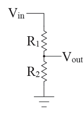
Figure 3-10. A representation of a potentiometer as two separate resistors
A schematic of the circuit is shown in Figure 3-11. You’ll be using the analog signal from the potentiometer on pin A5 to control the brightness of the LED on pin 9. In this circuit, both pin A5 and pin 9 have been chosen arbitrarily; any combination of analog input pin and PWM output pin will work.

Figure 3-11. Circuit layout for the potentiometer example
You’ll now pair the circuit with the Arduino code. First, declare the variables that you need: the pin numbers, the analog value read from the potentiometer, and the output brightness value for the LED:
intledPinAnalog=9;// LED pin, selected arbitrarilyintpotPinAnalog=A5;// Analog in potentiometer pin,// selected arbitrarilyintbrightness=0;// Initial brightness of 0, scale 0-255intpotValue=0;// Amount to increase the brightness each time
As in the last example, because you’re working with only analog pins, you can leave the setup function blank.
In the loop function, you’ll need to do two things: read the analog value from pin A5 using analogRead and then write the analog value out to pin 9 using analogWrite:
voidloop(){potValue=analogRead(potPinAnalog);analogWrite(ledPinAnalog,potValue);}
Serial Output
You can also use the serial console to view the values read from the potentiometer or any other analog sensor. This is a great way to get a feel for the range of values that a sensor will return.
One small problem still remains. The analogRead function returns a value from 0 to 1,023, but the analogWrite function is capped at 255. In order to make the full range of light correspond to the full turning range of the potentiometer, you need to scale the potentiometer values to the 0 to 255 range. The Arduino IDE comes with a function for just this purpose: map. The map function takes five inputs—the unscaled value, the low and high of the original range, and the low and high of the desired range—and returns the scaled value as an output. Insert map into the loop function as follows:
voidloop(){potValue=analogRead(potPinAnalog);brightness=map(potValue,0,1023,0,255);analogWrite(ledPinAnalog,brightness);}
Upload your code, and you’ll see that turning the potentiometer will adjust the LED brightness. Reading and writing analog signals opens up a wide range of devices to circuit programming. Outputs can be as varied as lights, and motors and inputs span all kinds of sensors: light, temperature, pressure, and even sound.
I2C Accelerometer
I2C (pronounced “I-squared-C” or “I-two-C” or “I-I-C”) is an acronym for inter-integrated circuit. It is a protocol developed by Philips Semiconductors in the late 1970s to simplify the lines that travel among various circuit components. From the previous examples, it’s probably already apparent that complicated circuits will lead to a ton of wired connections and a rather large number of I/Os if only analog and digital signals are used. The I2C protocol reduces the number of communication wires to two by allowing multiple peripherals to communicate on the same lines. In fact, you can wire up as many as 112 devices on just these two I2C lines.
Today, I2C has become so prevalent that there are literally hundreds of off-the-shelf components that use I2C to communicate with your Edison. These range from memory chips to LCD controllers and even amplifiers. For this example, we’ll be using an accelerometer.
The two lines that I2C requires are a data line (SDA) and a clock line (SCL). You can connect these to either the pins labeled SDA and SCL on the digital side of the board or pins A4 (SDA) and A5 (SCL) on the analog side. There are only two other lines that need to be connected: Vin on the accelerometer to 5V on the Edison board and GND on the accelerometer to any ground pin on the Edison board. Your wiring should look like Figure 3-12.

Figure 3-12. Wiring image for the I2C accelerometer example
In order to communicate with our I2C accelerometer, you need to load an Arduino library with a specific set of communication functions. This library is called Wire and can be loaded by adding the following to the very top of your Arduino code:
#include <Wire.h>In this example, all you do is confirm that the accelerometer is actually the device it’s supposed to be. To do so, you’ll have to transmit information to the I2C device, read back from it, and confirm that it gives the response you expect. To transmit information to the device, you’ll have to send at least two bytes: the unique address of the accelerometer, in this case 0x1D, and the register of the information you’re reading or writing. A register is the unique identifier of information on the device itself. Declare these two variables before the setup function. They are declared as constants because they will not change anywhere in the code:
constunsignedchar_i2caddr=0x1D;constunsignedcharMMA8451_REG_WHOAMI=0x0D;
Also declare a one-byte variable for the ID of the device that we’ll read back:
unsignedchardeviceid;
Hex Format
0x1D and 0x0D are numbers declared in hexadecimal, or base 16, format. A hexadecimal number is just a single byte integer in the range 0 to 255 written in a different format. It is the most common format in which to see device registers, addresses, and commands written.
Within the setup function, initialize serial output and then initialize communication with the device by calling begin:
Serial.begin(9600);Wire.begin();
Next, use the wire library to send the device address over the data line. This notifies the accelerometer that information is coming:
Wire.beginTransmission(_i2caddr);
Next, write the WHOAMI register to the device and request 1 byte back as a response:
Wire.write(MMA8451_REG_WHOAMI);Wire.endTransmission(false);// don’t end transmission// on MMA8451Wire.requestFrom(_i2caddr,1);
Finally, perform a series of checks using if statements:
if(Wire.available()){deviceid=Wire.read();/* Check connection */if(deviceid!=0x1A){/* No MMA8451 detected ... return false */Serial.println(deviceid,HEX);}else{Serial.println("MMA8541 Detected!");}}else{Serial.println("Device not connected.");}
Check if the device is available at all.
If the device is not available, print an error message, “Device not connected,” to the serial console.

If the device is connected, read the byte you requested.

If it does not return 0x1A, print the returned byte to the serial console.

If it does return as 0x1A as expected, then print the message, “MMA8541 was detected.”
The entire sketch is shown here:
constunsignedchar_i2caddr=0x1D;constunsignedcharMMA8451_REG_WHOAMI=0x0D;unsignedchardeviceid;voidsetup(){Serial.begin(9600);// put your setup code here, to run once:Wire.begin();Wire.beginTransmission(_i2caddr);Wire.write(MMA8451_REG_WHOAMI);Wire.endTransmission(false);// MMA8451 + friends use// repeated start!!Wire.requestFrom(_i2caddr,1);if(Wire.available()){deviceid=Wire.read();/* Check connection */if(deviceid!=0x1A){/* No MMA8451 detected ... return false */Serial.println(deviceid,HEX);}else{Serial.println("MMA8541 Detected!");}}else{Serial.println("Device not connected.");}}voidloop(){// NOTHING!}
When you run this sketch and open the serial console, you should see “MMA8541 Detected!” If not, check your wiring and make sure everything is connected properly.
You might be wondering if you’ll have to write all the programming for the MMA8541 this way. The answer is no. Arduino has a very active user community that almost always writes libraries to interface with the Arduino-compatible hardware. It is extremely rare that you’ll need to write any I2C calls from scratch as you just did. Specifically, the MMA8451 has an associated library that you can download from GitHub as a ZIP file. Unpack the file and remove the -master from the folder name (Arduino won’t read the -). Close the Arduino IDE and move this folder into the libraries directory within your main Arduino folder. Repeat the same process with the Adafruit sensor library. The MMA8451 code depends on this library and won’t run without it.
Now, restart the Arduino IDE, which will automatically source the new library files. Note that if you add new libraries while the Arduino IDE is still open, they will not be sourced. You have to close and reopen the IDE for the software to recognize them.
Go to File → Examples → Adafruit_MMA8451_Library and select the MMA8451demo file. Upload this sketch to your Edison and open the serial console when the upload finishes. The output should look like Figure 3-13.

Figure 3-13. Serial output of the MMA8451 accelerometer code
Despite saying m/s2, the units of the second line are actually in units of gravity (G), where 1 G is equal to 9.8 m/s2. If your accelerometer is sitting flat on a surface, then gravity in the z-direction should be close to 1, since it feels the earth’s gravity down, and the other two axes should be close to 0, since they experience very little gravity in those transverse directions. Using all three axes values, the accelerometer can calculate what orientation it’s in. This is listed below the values (here as “Portrait Up Front”). Move your accelerometer around and see how these values and orientations change. Tap or lightly drop your accelerometer and see what sort of readings you get. Accelerometers are incredibly useful devices; they’re used for everything from measuring car crash impact to orienting your smartphone display. Now you have your own hardware and tools for measuring acceleration and orientations.
SPI Screen
SPI, short for serial peripheral interface, is another standard protocol that is used to connect multiple peripherals to the same data lines. SPI operates using a slave-master architecture, meaning one device has full control over all peripherals. In the vast majority of cases, Edison will be your master device, controlling the slave devices that are attached to the SPI lines.
Unlike I2C, each SPI device requires four connections, one of which is not shared (thus each peripheral requires an additional pin):
- Master Out Slave In (MOSI, DOUT)
-
A shared line on which data is sent from the master to the slave. On the Arduino breakout, this is pin 11.
- Master In Slave Out (MISO, DIN)
-
A shared line on which data is sent from the slave device to the master. On the Arduino breakout, this is pin 12.
- Clock (CLK, SCLK, or SCK)
-
A shared line that provides the serial clock time from the master. On the Arduino breakout, this is pin 13.
- Slave Select (SS, CS, nSS, or nCS)
-
A digital output from the master stating whether this device is in use. Any digital pin can be used, and the default standard is that the device is active when this signal is low.
To transmit information over SPI, the SS pin is first set to low. Since each peripheral has its own SS pin, this selects the peripheral attached to that specific line for communication. Next, during each clock cycle, a bit is transmitted from master to slave over MOSI and then from slave to master over MISO. After the signal has been fully transmitted, the SS pin is set back to high, deactivating the communication with that particular device.
The device you’ll be using for SPI communication is the Adafruit 2.8” TFT Touch Screen Display. If you purchased the shield version, plug it in by recessing it into the Arduino breakout in its natural orientation (the direction in which the ICSP pins slide into place). If you’re instead using the breakout, wire it as shown on the second or third image on this page. The image shows an Arduino, but the pins are the same on the Edison Arduino breakout. Note that the first image when loading the page has a great many more connected wires. This is to utilize the full functionality—screen, resistive touch, and SD card—of the breakout board. For this example, we’ll just be using the screen, so not all of the wires are necessary.
For this example, you’ll be writing SPI instructions to the screen to adjust the display, which is driven by the ILI9341 controller. The ILI9341 controller is fairly popular as far as screens go, so you’ll be able to control the screen of any device that utilizes it if you’re interested in using something else.
Integrated Electronics
A lot of screens on Adafruit, Sparkfun, and other maker sights come with many integrated components: capacitive touch, resistive touch, SD card slots, etc. Before purchasing a screen, make sure to research these other components to ensure that libraries for Intel Edison are readily available for them. For example, Edison libraries exist for the STMPE610 resistive-touch element on the board we recommend for this chapter but are not as readily available for the FT2606 board on the capacitive touch model.
You’ll need two libraries for this example: a custom library for the ILI9341 for controlling the screen and the standard Adafruit GFX library for drawing certain preprogrammed shapes, lines, and text. Download both of these, unzip them, and move them into your Arduino libraries folder as in the last example. Make sure to completely quit out of the Arduino IDE and restart it so it can properly source these files.
First, you’ll do a simple example reading information from the device registers and marching “Hello World!” across the display screen. At the very top of a blank sketch, add the following:
#include "SPI.h"#include "Adafruit_GFX.h"#include "Adafruit_ILI9341.h"// Default SPI pins#define TFT_DC 9#define TFT_CS 10#define TFT_MOSI 11#define TFT_MISO 12#define TFT_CLK 13introw=0;intcol=0;Adafruit_ILI9341tft=Adafruit_ILI9341(TFT_CS,TFT_DC);
Import the libraries that you’ll need for communication.
Define the SPI communication pins as constants (as opposed to the variables that you’ve been using for other sketches).
Declare integers for the row and column positions.
Initialize the touchscreen object using the
Adafruit_ILI9341library functions.
#define Versus Variable Declaration
Using #define assigns a name to a constant value before the program is compiled, as opposed to declaring variables, which happens at compile time. Most microcontroller boards have low on-chip memory, and defining constants don’t occupy their precious program memory space on Arduino. Edison, however, has heaps of memory, so either defining or declaring should be fine in pretty much all instances.
Next, add the following as your setup function:
voidsetup(){Serial.begin(9600);Serial.println("ILI9341 Test!");// Begin tft object, init'ing SPI communictiontft.begin();// Read some diagnostic registers from the deviceuint8_tx=tft.readcommand8(ILI9341_RDMODE);Serial.("Display Power Mode: 0x");Serial.println(x,HEX);x=tft.readcommand8(ILI9341_RDPIXFMT);Serial.("Pixel Format: 0x");Serial.println(x,HEX);x=tft.readcommand8(ILI9341_RDSELFDIAG);Serial.("Self Diagnostic: 0x");Serial.println(x,HEX);}
Initialize serial communication and print a debug message to the screen.
Begin the information exchange with the touch screen.
Read some diagnostic information from the registers on the device, such as power mode, pixel format, and diagnostic.
Finally, you’ll program your actual drawing in the loop function:
voidloop(){// put your main code here, to run repeatedly:tft.fillScreen(ILI9341_BLACK);tft.setTextColor(ILI9341_WHITE);tft.setTextSize(1);tft.setCursor(row,col);tft.println("Hello World!");row+=10;col+=10;if(row>240){row-=240;}if(col>320){col-=320;}}
Fill the screen with black.
Set the text properties, such as color and size.
Set the cursor to the row and column location.
Print the text, “Hello World!” to the screen.
Add 10 to each of the row and column variables. By incrementing these variables each time through the loop, you make it appear as though the text is marching across and down the screen.

To ensure that the text doesn’t run off the bounds of the screen, use an
ifstatement to check that the row is less than the screen width, 240 pixels, and the column is less than screen height, 320 pixels.
Upload the sketch to your Intel Edison. “Hello World!” will march across the screen and if you open the Serial console, you’ll see the diagnostic information you requested in the setup function.
Finally, you can find several different example sketches in the examples folder of the ILI_9341 directory. Open the graphicstest.ino file within the graphicstest directory. Upload this sketch to your Edison, and you’ll see that it draws a wide array of shapes, forms, colors, and texts on the screen. You can use this file as a general template for drawing pretty much any image you can imagine.
Linux, C++, and the Arduino IDE
As mentioned in the Preface, programming Intel Edison using the Arduino IDE exposes all the libraries in the standard C++ distribution. One example that demonstrates this is the system function, which takes a single command-line command as an argument. This powerful function allows you to control the Linux command line from within the Arduino programming IDE. We can then redirect the command output to a file as you saw in Chapter 2, or you can pipe it to the Arduino serial console, which is simply the Linux path /dev/ttyGS0/. Using the latter technique allows you to see if you’re achieving the proper response from your system calls. Load the following code into a blank Arduino sketch:
voidsetup(){Serial.begin(9600);Serial.println("ifconfig test!");}voidloop(){system("ping -c 2 google.com &> /dev/ttyGS0");delay(5000);}
This code performs the following actions:
Initializes the serial console.
Uses the
systemcall to ping Google. This call pings Google twice each time through theloopfunction and outputs the response to the serial console.Sleeps for five seconds.
Upload it to your Intel Edison, and open the serial console to see the output. If you copied correctly and your Edison is connected to the Internet, you should see a similar response in your serial console every five seconds:
PING google.com (173.194.46.100): 56 data bytes
64 bytes from 173.194.46.100: icmp_seq=0 ttl=54 time=29.389 ms
64 bytes from 173.194.46.100: icmp_seq=1 ttl=54 time=24.394 ms

--- google.com ping statistics ---
2 packets transmitted, 2 packets received, 0.0% packet loss
round-trip min/avg/max/stddev = 24.394/26.892/29.389/2.497 ms
Because Edison is available via WiFi, you can also use it to serve web content through the Arduino IDE. As you saw in Chapter 2, Edison automatically begins running a web server at devicename.local or your Edison’s IP address upon connection to the Internet. On the Edison filesystem, this web server is located in the /usr/lib/edison_config_tools/public/ directory. Any files placed in this directory can be accessed at devicename.local/filename.
Edison and the Internet
In Chapter 2 I mentioned that you can access Edison’s web server so long as your host computer is connected to the same network. If you’d like to make your Edison accessible to the entire Internet, you’ll need to assign it a reserved IP address and enable port forwarding on your router. This will allow Edison to connect using the same IP address each time it gets online and send/receive information through your router’s firewall. Alternatively, a slightly more beginner-friendly and secure option is Weaved; an installer for Edison is available.
Wire up your Intel Edison as shown in Figure 3-7 and load or copy the following sketch into the Arduino IDE. This is mostly identical to the our original button sketch, except now each time you toggle the LED, you also set the text on your web page by echoing it to a file in the web-server directory:
intledPin=12;// LED pinintledState=0;// blink timing changed to ledStateintbuttonPin=2;// The choice of 8 is arbitraryintbuttonState=0;// Initialize the button state to zero. Zero is button “up”voidsetup(){pinMode(ledPin,OUTPUT);pinMode(buttonPin,INPUT);Serial.begin(9600);}voidloop(){if((buttonState==0)&&(digitalRead(buttonPin)==1)){ledState=1-ledState;digitalWrite(ledPin,ledState);system("echo '<html><head><title>LED State</title></head>' > /usr/lib/edison_config_tools/public/LEDstatus.html");if(ledState==0){system("echo '<body><h2>LED is OFF!</h2></body></html>' >> /usr/lib/edison_config_tools/public/LEDstatus.html");}else{system("echo '<body><h2>LED is ON!</h2></body></html>' >> /usr/lib/edison_config_tools/public/LEDstatus.html");}}buttonState=digitalRead(buttonPin);Serial.println(buttonState);// print the button state// to the consoledelay(100);}
Upload this sketch to your Intel Edison and open the page devicename.local/LEDstatus.html in a browser window. As you change the state of the LED by pressing the button, refresh your browser to see these changes reflected on your website. In this way, you can use Intel Edison and the Arduino IDE to serve information to the Web from sensors around your home.
Troubleshooting
There are definitely some subtleties in moving the pre-existing Arduino libraries to the x86 architecture that Intel Edison (and Intel Galileo) run on. You might find that you run into issues when trying to move Arduino sketches and examples over to your Edison. This is especially true when using hardware libraries that are outside the common core; for example, the LCD display libraries.
There are two sites I found that list Galileo-compatible shields:
If you want to use a shield on this list, then you’re probably in the clear with Intel Edison. Just because a shield is not on the list doesn’t mean that it won’t work, but it’s worth checking around on Google and the Intel Forums before purchasing.
Fortunately, Edison has a wide and growing user community that is working hard to enable more off-the-shelf Arduino programming each and every day. If you encounter problems, the first places you should check are the Edison Forums and the Edison Troubleshooting Guide.
Going Further
Now that you’ve mastered some basic examples and circuits, there’s so much more to explore. The following resources provide a good starting point for going further:
- Make: Electronics
-
Maker Media’s introductory guide to electrical components and circuitry. A great overview of modern maker electronics.
- Arduino Cookbook
-
A great guide, for beginners and advanced users, to programming with Arduino.
- Learn C++
-
A very comprehensive series of tutorials in learning how to program C++. Learning C++ is useful not only for leveraging the full power of the programming language in the Arduino IDE, but also for writing standalone applications that can run on your Intel Edison. Slightly more to come on this in Chapter 7.
1 All circuit layouts and circuit diagrams in this book were created using the amazing Fritzing software.
2 I’m paraphrasing here and simplifying quite a bit. For a full description, see the Wikipedia page.