
Chapter Syllabus
Partitioning is not a new concept in the computing industry. Man vendors have provided some form of partitioning as a software and/or a hardware solution for some years. The basic idea of partitioning is to create a configuration of hardware and software components that supports the running of an independent instance of an operating system. HP currently supports two types of partitioning:
nPar or Node Partition
vPar or Virtual Partition
This chapter deals with Node Partitions and Chapter 3 deals with Virtual Partitions.
An nPar is a collection of electrically independent components that support the running of a separate instance of the operating system completely independent of other partitions. The collection of hardware components that support Node Partitions is collectively known as a server complex. By using software management tools, we can configure the complex to function as either a large, powerful, single server or a collection of powerful but smaller, independent servers. HP's recent foray into the Node Partitions started in 2000 with the introduction of the first range of Superdome complexes. HP now provides Node Partitions via a range of complexes running either PA-RISC or Itanium-2 processors (for more details on HP's partitioning continuum initiative, see http://www.hp.com/products1/unix/operating/manageability/partitions/index.html). Node partitionable machines utilize a cell-based hardware architecture in order to support the electronic independence of components, which in turn allows the complex to support Node Partitions.
The flexibility in configuration makes partitioning a popular configuration tool. Some key benefits of partitioning include:
Better system resource utilization
Flexible and dynamic resource management
Application isolation
Server consolidation
In the future, different partitions will be able to run various versions of HP-UX, Windows, and Linux simultaneously with different processors in each partition within the same complex. This offers significant investment protection as well as configuration flexibility and cost savings with respect to server consolidation within the datacenter.
As you can imagine, trying to cover all permutations of configuration in this chapter would take considerable time. Consequently during our discussions, we use a PA-RISC Superdome (SD32000) complex to display some of the techniques in creating and managing nPars. The concepts are the same regardless of the complex you are configuring. Many of the components that are used in Superdome complexes are also used in the other Node Partitionable machines. I use screenshots and photographs from a real-life Superdome system to explain the theory and practice of the concepts discussed. We start by looking at the partition configuration supplied by HP when your complex is delivered. We then discuss why, how, and if I would want to change that configuration including scrapping the entire configuration and starting again, which is known as creating the Genesis Partition. We also discuss day-to-day management tasks involved with partitioned servers. I would suggest having access to your own system configuration while reading through this chapter as well as access to the excellent HP documentation: HP Systems Partitions Guide available at http://docs.hp.com/hpux/onlinedocs/5187-4534/5187-4534.html. Most of the concepts relating to Node Partitions relate to any of the Node Partitionable complexes supplied by HP. Where a specific feature is unique to a certain operating system release of a particular architecture (PA-RISC or Itanium), I highlight it.
An nPar is a Node Partition, sometimes referred to as a Hard Partition. An nPar can be considered as a complete hardware and software solution that we would normally consider as an HP server. When we think about the basic hardware components in an HP server, we commonly think about the following:
At least one CPU
Memory
IO capability
An external interface to manage and configure the server, i.e., a system console
An operating system
In exactly the same way as a traditional server, an nPar is made of the same basic components. A major difference between a Node Partition and a traditional server is that a traditional server is a self-contained physical entity with all major hardware components (CPU, memory, and IO interfaces) contained within a single cabinet/chassis. A node partition is a collection of components that may form a subset of the total number of components available in a single hardware chassis or cabinet. This subset of components is referred to as a node partition while the entire chassis/cabinet is referred to as a server complex. HP's implementation of Node Partitions relies on a hardware architecture that is based on two central hardware components known as:
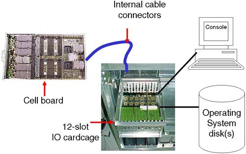
A cell board, which contains a CPU and RAM
An IO cardcage, which contains PCI interface cards
A cell board plus an IO cardcage form most of the basic components of how we define an nPar.
Some partitionable servers have internal storage devices, i.e., disks, tape, CD/DVD. A Superdome complex has no internal storage devices.
In order for the complex to function even as a single server, it is necessary to configure at least one node partition. Without a Complex Profile, the complex has no concept of which components should be working together.
The list of current Node Partitionable servers (see http://www.hp.com—Servers for more details) is extensive and will continue to grow. While the details of configuring each individual server may be slightly different, the concepts are the same. It is inconceivable to cover every configuration permutation for every server in this chapter. In order to communicate the ideas and theory behind configuring nPars, I use a PA-RISC Superdome (SD32000) complex during the examples in this chapter.
An important concept with Node Partitionable servers is to understand the relationship between the major underlying hardware components, i.e., which cells are connected to which IO cardcages. For some people, this can seem like overcomplicating the issue of configuring nPars. Without this basic understanding, we may produce a less-than-optimal partition configuration. An important concept to remember when configuring nPars (in a similar way when we configure any other server) is that we are aiming to provide a configuration that achieves two primary goals:
Without an understanding of how the major hardware components interrelate, as well as any Single Points of Failure in a server complex, our configuration decisions may compromise these two primary goals.
The primary components of a server complex are the cell board and the IO cardcage. These are the hardware components we need to consider first.
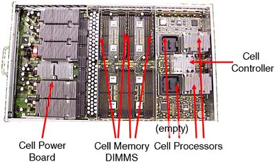
A cell board (normally referred to as simply a cell) is a hardware component that houses up to four CPU modules. (Integrity servers support dual-core processors. Even though these dual-core processors double the effective number of processors in the complex, there are physically four CPU slots per cell. In each CPU slot a single, dual-core processors can be installed.) It also houses a maximum of 32 DIMM slots (on some Superdome solutions, this equates to 32GB of RAM per cell).
Depending on the server we have, determines how many cell boards we have. The cell boards are large and heavy and should be handled only by an HP qualified Customer Engineer. The cells slot into the front of the main cabinet and connect to the main system backplane. A cell board can optionally be connected (via the backplane) to an IO cardcage (sometimes referred to as an IO chassis). On a Superdome server, this is a 12-slot PCI cardcage; in other words, the IO chassis can accommodate up to 12 PCI cards. On other servers, this is usually an 8-slot PCI cardcage.
If a cell is connected to an IO cardcage, there is a one-to-one relationship between that cell board and the associated IO cardcage. The cell cannot be connected to another IO cardcage at the same time, and similarly the IO cardcage cannot be connected or shared with another cell.
Some customers I have worked with have stipulated minimal CPU/RAM requirements and extensive IO capabilities. If you need more than 12 PCI slots (on a Superdome), you need to configure an nPar with at least two cells, each cell connected to its own IO cardcage; in other words, you cannot daisy-chain multiple IO cardcages off one cell board. This may have an impact on our overall partition configuration.
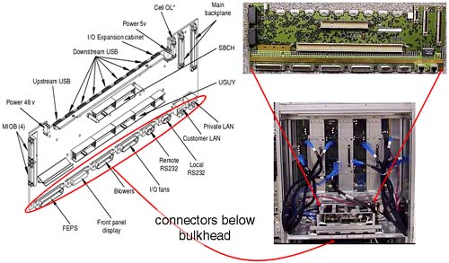
The interface between cell components is managed by an ASIC (Application Specific Integrated Circuit) housed within the cell and is called the Cell Controller chip (see Figure 2-2). Communication to the IO subsystem is made from the Cell Controller, through the system backplane to an IO cardcage via thick blue cables knows as RIO/REO/Grande cables to an ASIC on the IO cardcage known as the System Bus Adapter (SBA). You can see these blue cables in Figure 2-4 and Figure 2-5. Performing a close physical inspection of a server complex is not recommended because it involves removing blanking plates, side panels, and other hardware components. Even performing a physical inspection will not reveal which cells are connected to which IO cardcages. We need to utilize administrative commands from the Guardian Service Processor (GSP) to establish how the complex has been cabled; we discuss this in more detail later.
As mentioned previously, a cell board has an optional connection to an IO cardcage. This means that, if we have massive processing requirements but few IO requirements, we could configure an 8-cell partition with only one cell connected to an IO cardcage. This flexibility gives us the ability to produce a Complex Profile that meets the processing and IO requirements of all our customers utilizing the complex.
Within a complex, there are a finite number of resources. Knowing what hardware components you have is crucial. Not only knowing what you have but how it is connected together is an important part of the configuration process (particularly in a Superdome). With a partitioned server, we have important choices to make regarding the configuration of nPars. Remember, we are ultimately trying to achieve two basic goals with our configuration; those two goals are High Availability and High Performance. Later, we discuss criteria to consider when constructing a partition configuration.
The IO cardcage is an important component in a node partition configuration. Without an IO cardcage, the partition would have no IO capability and would not be able to function. It is through the IO cardcage that we gain access to our server console as well as access to all our IO devices. We must have at least one IO cardcage per node partition. At least one IO cardcage must contain a special IO card called the Core IO Card. We discuss the Core IO Card in more detail later.
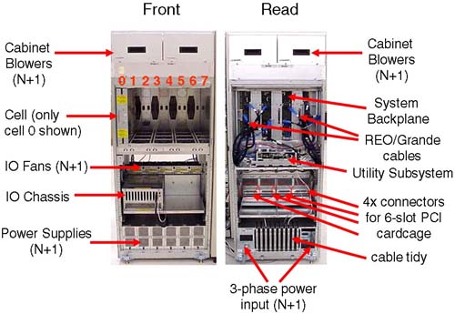
If an IO cardcage is connected to a cell board and the cell is powered on, we can use the PCI cards within that cardcage. If the cell is powered off, we cannot access any of the PCI cards in the IO cardcage. This further emphasizes the symbiotic relationship between the cell board and the IO cardcage. Depending on the particular machine in question, we can house two or four IO cardcages within the main cabinet of the system complex. In a single cabinet Superdome, we can accommodate four 12-slot PCI cardcages, two in the front and two in the back. If we look carefully at the IO backplane (from our Superdome example) to which the IO cardcages connect (Figure 2-3), there is the possibility to accommodate eight 6-slot PCI IO cardcages in a single cabinet. As yet, HP does not sell a 6-slot PCI IO cardcage for Superdome.
We can fit two 12-slot IO cardcages in the front of the cabinet; this is known as IO Bay 0. We can fit a further two 12-slot IO cardcages in the rear of the cabinet; this is known as IO Bay 1. You may have noticed in Figure 2-3 that there appear to be four connectors per IO bay (numbered from the left, 0, 1, 2 and 3); connectors number 0 and 2 are not used. Believe it or not, it is extremely important that we know which cells are connected to which IO cardcages. Taking a simple example where we wanted to configure a 2-cell partition with both cells connected to an IO cardcage, our choice of cells is important from a High Availability and a High Performance perspective. From a High Availability perspective, we would want to choose cells that were connected to one IO cardcage in IO Bay 0 and one in IO Bay 1. The reason for this is that both IO Bays have their own IO Backplane (known as a HMIOB = Halfdome Master IO Backplane). By default, certain cells are connected to certain IO cardcages. As we can see from Figure 2-3, by default cell 0 is connected to an IO cardcage located in the rear left of the main cabinet (looking from the front of the cabinet), while cell 6 is connected to the IO cardcage front right of the cabinet. It may be that your system complex has been cabled differently from this default. There is no way of knowing which cell is connected to which IO cardcage simply by a physical inspection of the complex. This is where we need to log in to the GSP and start to use some GSP commands to analyze how the complex has been configured, from a hardware perspective.
There is a numbering convention for cells, IO bays, and IO cardcages. When we start to analyze the partition configuration, we see this numbering convention come into use. This numbering convention, known as a Slot-ID, is used to identify components in the complex: components such as individual PCI cards. Table 2-1 shows a simple example:
We get to the cabinet numbering in a moment. The Slot-ID allows us to identify individual PCI cards (this is very important when we perform OLA/R on individual PCI cards in Chapter 4 Advanced Peripherals Configuration).
It should be noted that the cabling and cell–IO cardcage connections shown in Figure 2-3 is simply the default cabling. Should a customer specification require a different configuration, the complex would be re-cabled accordingly. Re-cabling a Superdome complex is not a trivial task and requires significant downtime of the entire complex. This should be carefully considered before asking HP to re-cable such a machine.
The only card in the IO cardcage that is unique and has a predetermined position is known as the Core IO card. This card provides console access to the partition via a USB interface from the PCI slot and the PACI (Partition Console Interface) firmware on the Core IO card itself. The only slot in a 12-slot PCI cardcage that can accommodate a Core IO card is slot 0. The PACI firmware gives access to console functionality for a partition. There is no physically separate, independent console for a partition. The Guardian Service Processor (GSP) is a centralized location for the communication to-and-from the various PACI interfaces configured within a complex. A partition must consist of at least one IO cardcage with a Core IO card in slot 0. When a Core IO card is present in an IO cardcage, the associated cell is said to be core cell capable. Core IO cards also have an external serial interface that equates to /dev/tty0p0. This device file normally equates to the same device as /dev/console. In node partitions, /dev/console is now a virtual device with /dev/tty0p0 being the first real terminal on the first mux card. Some Core IO cards also have an external 10/100 Base-T LAN interface. This device equates to lan0, if it exists and is nothing to do with the GSP LAN connections. Because the Core IO card can be located only in slot 0, it is a good idea to configure a partition with two IO cardcages with a Core IO card in each cardcage. While only one Core IO card can be active at any one time, having an additional Core IO card improves the overall availability of the partition.
If we were to take a complex configured using the default wiring we saw in Figure 2-3 and a requirement to create a 2-cell partition, it would make sense to choose cells 0 and 2, 0 and 6, 4 and 2, or 4 and 6, because all of these configurations offer us a partition with two IO cardcages, one in each IO Bay. It is not a requirement of a partition to have two IO cardcages but it does make sense from a High Availability perspective; in other words, you could configure your disk drives to be connected to interface cards in each IO cardcage. To further refine our search for suitable cell configurations, we need to discuss another piece of the hardware architecture of Node Partitionable complexes—the system backplane and how cells communicate between each other.
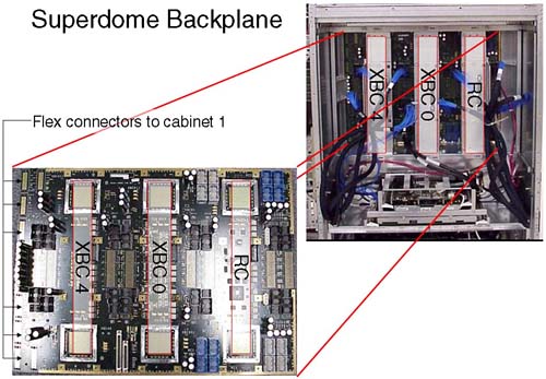
The XBC interface is known as the CrossBar interface and is made up of two ASIC (Application Specific Integrated Circuit) chips. The XBC interface is a high-throughput, non-blocking interface used to allow cells to communicate with each other (via the Cell Controller chip). A cell can potentially communicate with any other cell in the complex (assuming they exist in the same nPar). For performance reasons, it is best to keep inter-cell communication as local as possible, i.e., on the same XBC interface. If this cannot be achieved, it is best to keep inter-cell communication in the same cabinet. Only when we have to, do we cross the flex-cable connectors to communicate with cells in the next cabinet. [The Routing Chips (RC) are currently not used. They may come into use at some time in the future.] An XBC interface connects four cells together with minimal latency; XBC0 connects cells 0, 1, 2, and 3 together, and XBC4 connects cells 4, 5, 6, and 7 together. This grouping of cells on an XBC is known as an XBC quad. If we are configuring small (2-cell) partitions, it is best to use even or odd numbered cells (this is a function of the way the XBC interface operates). The memory latencies involved when communicating between XBC interfaces is approximately 10-20 percent, with an additional 10-20 percent increase in latency when we consider communication between XBCs in different cabinets. We return to these factors when we consider which cells to choose when building a partition.
We have only one system backplane in a complex. (In a dual-cabinet solution, we have two separate physical backplane boards cabled together. Even though they are two physically separate entities, they operate as one functional unit.) In some documentation, you will see XBC4 referred to a HBPB0 (Halfdome BackPlane Board 0), XBC0 as HBPB 1, and the RC interface referred to as HBPB2. Some people assume that these are independent “backplanes.” This is a false assumption. All of the XBC and RC interfaces operate within the context of a single physical system backplane. If a single component on the system backplane fails, the entire complex fails. As such the system backplane is seen as one of only three Single Points Of Failure in a complex.
We have mentioned the basic building blocks of an nPar:
A cell board
An IO cardcage
A console
An operating system stored on disk (which may be external to the complex itself)
Before going any further, we look at how these components relate to each other in our Superdome example. It is sometimes a good idea to draw a schematic diagram of the major components in your complex. Later we establish which cells are connected to which IO cardcages. At that time, we could update our diagram, which could subsequently be used as part of our Disaster Recovery Planning:
This is a single cabinet Superdome, i.e., a 16-way or 32-way configuration. A dual-cabinet Superdome is available where two single cabinets are located side by side and then cabled together. To some people, the dual-cabinet configuration looks like two single cabinets set next to each other. In fact, a considerable amount of configuration wiring goes into making a dual-cabinet complex, including wiring the two backplanes together to allow any cell to communicate with any other cell. You can see in Figure 2-5 that we have a single-cabinet solution. I have included the numbering of the cell boards, i.e., from left to right from 0 through to 7. In a dual-cabinet solution, the cell boards in cabinet 1 would be numbered 8–15.
A single cabinet can accommodate up to eight cells but only four IO cardcages. If we were to take a single-cabinet solution, we would be able to create four partitions as we only have 4 IO cardcages. This limitation in the number of IO cardcages frequently means that a complex will include an IO expansion cabinet. An IO expansion cabinet can accommodate an additional four IO cardcages. Each cabinet in a complex is given a unique number, even the IO expansion cabinets. Figure 2-6 shows the cabinet numbering in a dual-cabinet solution with IO expansion cabinet(s).
The IO expansion cabinets (numbered 8 and 9) do not have to be sited on either side of cabinets 0 and 1; they can be up to 14 feet away from the main cabinets. The reason the IO expansion cabinets are numbered from 8 is that Superdome has a built-in infrastructure that would allow for eight main cabinets (numbered 0 through to 7) containing cell-related hardware (CPU, RAM, and four 12-slot PCI cardcages) connected together using (probably) the Routing Chips that are currently left unused. Such a configuration has yet to be developed.
If we carefully plan our configuration, we can achieve both goals of High Availability and High Performance. Machines such as Superdome have been designed with both goals in mind. To achieve both goals may require that we make some compromises with other parts of our configuration. Understanding why these compromises are necessary is part of the configuration process.
We have mentioned some High Availability and High Performance criteria when considering choice of cells and IO cardcages. We need to consider the amount of memory within a cell as well. By default, cell-based servers use interleaved memory between cells to maximize throughput; in other words, having two buses is better than one. [HP-UX 11i version 2 on the new Integrity Superdomes can configure Cell Local Memory (CLM), which is not interleaved with other cells in the partition. Future versions of HP-UX on PA-RISC and Itanium will allow the administrator to configure Cell Local Memory as and when appropriate.] To maximize the benefits of interleaving, it is best if we configure the same amount of memory in each cell and if the amount of memory is a power of 2 GBs.
The way that memory chips are used by the operating system (i.e., the way a cache line is constructed) also dictates the minimum amount of memory in each cell. The absolute minimum amount of memory is currently 2GB. This 2GB of memory is comprised of two DIMMs in the new Integrity servers (the two DIMMs are collectively known as an Echelon) or four DIMMs in the original cell-based servers (the four DIMMs are collectively known as a Rank). If we configure a cell with only a single Echelon/Rank and we lose that Echelon/Rank due to a hardware fault, our cell would fail to pass its Power-On Self Test (POST) and would not be able to participate in the booting of the affected partition. Consequently, it is strongly advised that we configure at least two Echelons/Ranks per cell. The same High Availability criteria can be assigned to the configuration of CPUs, i.e., configure at least two CPUs per cell and the same number of CPUs per cell. These and other High Availability and High Performance criteria can be summarized as follows:
Configure your largest partitions first.
Minimize XBC traffic by configuring large partitions in separate cabinets.
Configure the same number of CPUs per cell.
Configure the same amount of memory per cell.
Configure a power of 2 GB of memory to aid memory interleaving.
Configure the number of cells per partition as a power of 2. An odd number of cells will mean that a portion of memory is interleaved over a subset of cells.
Choose cells connected to the same XBC.
Configure at least two CPUs per cell.
Configure at least two Echelons/Rank of memory per cell.
Use two IO cardcages per partition.
Install a Core IO card in each IO cardcage.
Use even and then odd numbered cells.
A maximum of 64 processors per partitions, e.g., 32 dual-core processors = 64 processors in total.
If we marry this information back to our discussion on the default wiring of cells to IO cardcages, we start to appreciate why the default wiring has been set up in the way it has. We also start to realize the necessity of understanding how the complex has been configured in order to meet both goals of High Availability and High Performance. In the simple 2-cell example that we discussed earlier, it now becomes apparent that the optimum choice of cells would either be 0 and 2 or 4 and 6:
Both cells are located on the same XBC minimizing latency across separate XBC interfaces.
Both cells are already wired to a separate IO cardcages on separate IO backplanes.
Inter-cell communication is optimized between even or odd cells.
As you can imagine, the combination of cell choices for a large configuration are quite mind-blowing. In fact with a dual-cabinet configuration where we have 16 cells, the number of combinations is 216 = 65536. Certain combinations are not going to work well, and in fact HP has gone so far as to publish a guide whereby certain combinations of cells are the only combinations that are supported. Remember, the idea here is to produce a configuration that offers both High Availability and High Performance. The guide to choosing cells for a particular configuration is affectionately known as the nifty-54 diagram (out of the 65536 possible combinations, only 54 combinations are supported). For smaller partitionable servers, there is a scaled-down version of the nifty-54 diagram (shown in Figure 2-7) appropriate to the number of cells in the complex.
Let's apply the nifty-54 diagram to a fictitious configuration, which looks like the following (assuming that we have a 16-cell configuration):
One 6 cell partition
Two 3 cell partitions
One 2 cell partition
If we apply the rules we have learned and use the nifty-54 diagram, we should start with our largest partition first.
One 6 cell partition
We look down the left column of the nifty-54 diagram until we find a partition size of six cells (approximately halfway down the diagram). We then choose the cell numbers that contain the same numbers/colors. In this case, we would choose cells 0-4, 5, and 7 from either cabinet 0 or 1. Obviously, we can't keep all cells on the same XBC (the XBC can only accommodate four cells). Assuming that we have the same number/amount of CPU/RAM in each cell, we have met the High Performance criteria. In respect of High Availability, this partition is configured with two IO cardcages; by default cells 0 and 2 are connected to an IO cardcage and each IO cardcage is in a different IO bay and, hence, connected to independent IO backplanes.
Partition 0:
Cells from Cabinet 0 = 0, 1, 2, 3, 5, and 7.
Two 3 cell partitions
We would go through the same steps as before. This time, I would be using cells in cabinet 1 because all other cell permutations are currently being used by partition 0. The lines used in the nifty-54 diagram are in the top third of the diagram.
Partition 1:
Cells from Cabinet 1 = 0, 1, and 2.
Partition 2:
Cells from Cabinet 1 = 4, 5, and 6.
Another thing to notice about this configuration is that both partitions are connected to two IO cardcages (cells 0 and 2 as well as cells 4 and 6) by default. This is the clever part of the nifty-54 diagram.
One 2-cell partition
Another clever aspect of the nifty-54 diagram comes to the fore at this point. We could use cells 3 and 7 from cabinet 1, but they are on a different XBC, which is not good for performance. The ideal here is cells 4 and 6 from cabinet 0; they are on the same XBC and are each by default connected to an IO cardcage. The nifty-54 diagram was devised in such a way to maximize High Performance while maintaining High-Availability in as many configurations as is possible.
Partition 3:
Cells from Cabinet 0 = 4 and 6.
Cells 3 and 7 in cabinet 1 are left unused. If partition 1 or partition 2 needs to be expanded in the future, we can use cell 3 for partition 1 and cell 7 for partition 2 because these cells are located on the same XBC as the original cells and, hence, maintain our High Performance design criteria.
This is a good configuration.
I am sure some of you have noticed that I have conveniently used all of my IO cardcages. If I wanted to utilize the two remaining cells (cells 3 and 7) in cabinet 1 as separate 1-cell partitions, I would need to add an IO Expansion cabinet to my configuration. In fact if we think about it, with a dual-cabinet configuration we can configure a maximum of eight partitions without resorting to adding an IO Expansion cabinet to our configuration (we only have eight IO cardcages within cabinets 0 and 1). If we wanted to configure eight partitions in such a configuration, we would have to abandon our High Availability criteria of using two IO cardcages per partition. This is a cost and configuration choice we all need to make.
NOTE: An important part of the configuration process is to first sit down with your application suppliers, user groups, and any other customers requiring computing resources from the complex. You need to establish what their computing requirements are before constructing a complex profile. Only when we know the requirements of our customers can we size each partition.
At this point, I am sure that you want to get logged into your server and start having a look around. Before you do, you need to have a few words regarding the Utility Subsystem. Referring back to Figure 2-5, a blanking plate normally hides the cells and system backplane/utility subsystem. In normal day-to-day operations, there is no reason to remove the blanking plate. Even if you were to remove it, there is no way to determine which cells are connected to which IO cardcages. It is through the Utility Subsystem that we can connect to the complex and start to analyze how it has been configured.
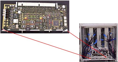
The administrative interface (the console) to a partitionable server is via a component of the Utility Subsystem known as the Guardian Service Processor (GSP). As a CSA, you have probably used a GSP before because they are used as a hardware interface on other HP servers. The GSP on a partitionable server operates in a similar way to the GSP on other HP servers with some slight differences that we see in a few minutes. There is only one GSP in a server complex, although you may think you can find two of them in a dual-cabinet configuration. In fact, the GSP for a dual-cabinet configuration always resides in cabinet 0. The board you find in cabinet 1 is one of the two components that comprise the GSP. The GSP is made up two components piggy-backed on top of each other: a Single Board Computer (SBC) and a Single Board Computer Hub (SBCH). The SBC has a PC-based processor (an AMD K6-III usually) as well as a FLASH card, which can be used to store the Complex Profile. There is an SBCH in each cabinet in the complex because it holds an amount (6 or 12MB) of NVRAM, USB hub functionality, as well as two Ethernet and two serial port interfaces. The USB connections allow it to communicate with other SBCH boards in other cabinets. Even though there is only one GSP in a complex, it is not considered a Single Point Of Failure, as we will see later. The whole assembly can be seen in Figure 2-8.
From this picture, we cannot see the two serial or two LAN connections onto the GSP. The physical connections are housed on a separate part of the Utility Subsystem. This additional board is known as the Halfdome Utility Communications (or Connector) Board (HUCB). It is difficult to see an HUCB even if you take off the blanking panel in the back of the cabinet. The GSP locates into the rear of the cabinet on a horizontal plane and plugs into two receptacles on the HUCB. The HUCB sits at 90° to the GSP. You can just about see the HUCB in Figure 2-9.
Because the HUCB is the interface board for the entire Utility Subsystem, if it fails, the entire complex fails. The HUCB is the second Single Point Of Failure in a Superdome Complex.
The last component in the Utility Subsystem is known as the Unified (or United, or Universal) Glob of Utilities for Yosemite, or the UGUY (pronounced oo-guy). As the name alludes, the UGUY performs various functions including:
System clock circuitry.
The cabinet power monitors, including temperature monitoring, door open monitoring, cabinet LED and switch, main power switch, main and IO cooling fans.
Cabinet Level Utilities, including access to all backplane interfaces, distribute cabinet number and backplane locations to all cabinets, interface to GSP firmware and diagnostic testing, drive all backplane and IO LEDs.
If we have a dual-cabinet configuration, we have two physical UGUY boards installed. The UGUY in cabinet 0 is the main UGUY with the UGUY in cabinet 1 being subordinate (only one UGUY can supply clock signals to the entire complex). The UGUY plugs into the HUCB in the same way as the GSP. You can see the UGUY situated below the GSP in Figure 2-10.
The UGUY in cabinet 0 is crucial to the operation of the complex. If this UGUY fails, the entire complex fails. The UGUY is the third and last Single Point Of Failure in a Superdome Complex.
Now it's time to talk a little more about the GSP. This is our main interface to the server complex. The GSP supports four interfaces—two serial connections and two 10/100 Base-T network connections. Initially, you may attach an HP terminal or a laptop PC in order to configure the GSP's network connections. We look at that later. Once connected, you will be presented with a login prompt. There are two users preconfigured for the GSP: One is an administrator-level user, and the other is an operator-level user. The administrator-level user has no restrictions, has a username of Admin, and a password the same as the username. Be careful, because the username and password are case-sensitive.
GSP login: Admin
GSP password:


(c)Copyright 2000 Hewlett-Packard Co., All Rights Reserved.


                             Welcome to

               Superdome's Guardian Service Processor


    GSP MAIN MENU:

Utility Subsystem FW Revision Level: 7.24
         CO: Consoles
        VFP: Virtual Front Panel
         CM: Command Menu
         CL: Console Logs
         SL: Show chassis Logs
         HE: Help
          X: Exit Connection

GSP>
Before we get into investigating the configuration of our complex, we discuss briefly the configuration of the GSP.
The two 10/100 Base-T network connections have default IP addresses:
Customer LAN = 192.168.1.1
Private LAN = 15.99.111.100
The Private LAN is intended to be used by support personnel for diagnostic troubleshooting. In fact, an additional piece of hardware that you need to purchase with a Superdome server is a machine known as the Support Management Station (SMS). Originally, this would have been a small HP-UX server such as an rp2400. With the introduction of Integrity Superdomes, the SMS is now a Win2K-based server such as an HP Proliant PC. The SMS device can support up to 16 complexes. It is used exclusively by HP support staff to check and if necessary to download new firmware to a complex (remember, a Superdome complex has no internal IO devices). I know of a number of customers who use their (HP-UX based) SMS as a Software Distributor depot-server as well as a place to store HP-UX crashdumps in order to allow HP Support staff to analyze them without logging into an actual partition. The SMS does not need to be up and running to operate the complex but will have to be powered on and operational should HP Support staff require access for diagnostic troubleshooting purposes.
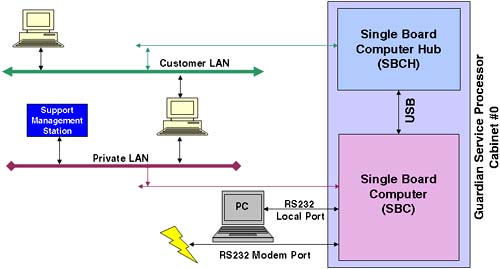
The Customer LAN is intended to be used by internal staff to connect to the GSP. Although the Private LAN and the Customer LAN may appear to have at some level different basic functionality, they offer the same level of functionality and are simply 10/100 Base-T network interfaces. The idea behind a Private LAN is to avoid having HP Support staff access a customer's corporate network. You do not need to connect or configure the Private LAN, although it is suggested that you have some form of network access from the GSP to the SMS station for diagnostic/troubleshooting purposes.
The Local serial port is a 9-pin RS232 port designed to connect to any serial device with a null modem cable. The Remote serial port is a 9-pin RS232 port designed for modem access. Both RS232 ports default to 9600 baud, 8-bit, no parity, and HP-TERM compatibility. These defaults can be changed through the GSP, as we see later.
The default IP addresses and the default username/password combinations should be changed as soon as possible. Should you forget or accidentally delete all administrator-level users from the GSP, you can reset the GSP to the factory default settings. To initiate such a reset, you can press the button marked on the GSP “Set GSP parameters to factory defaults” (see Figure 2-12).
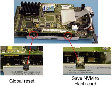
The switch marked “NVM Mode for Uninstalled GSP” allows you to write your Complex profile to the Flash-card. This can be useful if you are moving the Flash-card to another complex or you need to send the complex profile to HP for diagnostic troubleshooting. By default, the Complex Profile is held in NVRAM on the GSP and read from cell boards when necessary; in other words, the switch is set to the “Clear” position by default.
When installed, the GSP holds in NVRAM the current Complex Profile. Any changes we make to the Complex Profile, e.g., using Partition Manager commands, are sent to the GSP. The GSP will immediately send out the new Complex Profile to all cells. Every cell in the complex holds a copy of the entire Complex Profile even though only part of it will pertain to that cell. The Complex profile is made up of three parts:
The Stable Complex Configuration Data (SCCD) contains information that pertains to the entire complex such as the name of the complex (set by the administrator), product name, model number, serial number, and so on. The SCCD also contains the cell assignment array, detailing which cells belong to which partitions.
Dynamic Complex Configuration Data (DCCD) is maintained by the operating system. There is no way currently for any of the system boot interfaces to modify this data, so it is transparent to the user.
Partition Configuration Data (PCD) contains partition specific information such as partition name, number, usage flags for cells, boot paths, core cell choices, and so on.
Changes can be made to the Complex Profile from any partition, although only one change to the SCCD can be pending. Whenever a change affects a particular cell, that cell (and the partition it affects) will need to be rebooted in such a way as to make the new SCCD the current SCCD. Other cells that are not affected do not need to be rebooted in this way. This limitation means that adding and removing cells to a partition requires a reboot of at least that partition (assuming that no other cells currently active in another partition are involved). This special reboot is known as a reboot-for-reconfig and requires the use of a new option to the shutdown/reboot command (option –R).
Because the Complex Profile is held on every cell board, the GSP is not considered to be a Single Point Of Failure. If the GSP is removed, the complex and cells will function as normal, using the Complex Profile they have in NVRAM on the cell board. When the GSP is reinserted, it will contact all cells in order to reread the Complex Profile. The Complex Profile is surrounded by timestamp information just to ensure that the GSP obtains the correct copy (a cell board could be malfunctioning and provide invalid Complex Profile data). A drawback of not having the GSP inserted at all times is that the GSP also captures Chassis/hardware/console logs, displays complex status, and allows administrators to interface with the system console for each partition. Without the GSP inserted and working, no changes to the Complex Profile are allowed. It is suggested that the GSP is left inserted and operating at all times.
There are a number of screens and commands that we should look at on the GSP. Right now, I want to get logged into the GSP and investigate how this complex has been configured.
Once logged into the GSP, we will perform our initial investigations from the “Command Menu”:
GSP login: Admin
GSP password:


(c)Copyright 2000 Hewlett-Packard Co., All Rights Reserved.


                             Welcome to

               Superdome's Guardian Service Processor


    GSP MAIN MENU:

Utility Subsystem FW Revision Level: 7.24

         CO: Consoles
        VFP: Virtual Front Panel
         CM: Command Menu
         CL: Console Logs
         SL: Show chassis Logs
         HE: Help
          X: Exit Connection

GSP>
GSP> cm
                Enter HE to get a list of available commands


GSP:CM>
There are quite a few commands available at the GSP Command Menu. I will use the commands that allow us to build up a picture of how this complex has been configured. By default, HP works with technical individuals in a customer organization to establish the Complex Profile that will be in place before the Superdome is shipped to the customer. While performing the following commands, it might be an idea to draw a diagram of your complex so that you can visualize how the complex has been configured. You can use this diagram as part of your Disaster Recovery Planning documentation. We can get an immediate insight as to which cells are assigned to which partitions by using the CP command:
GSP:CM> cp

--------------------------------------------------------------------------------
Cabinet |   0    |   1    |   2    |   3    |   4    |   5    |   6    |   7
--------+--------+--------+--------+--------+--------+--------+--------+--------
 Slot   |01234567|01234567|01234567|01234567|01234567|01234567|01234567|01234567
--------+--------+--------+--------+--------+--------+--------+--------+--------
Part  0 |X.......|........|........|........|........|........|........|........
Part  1 |....X...|........|........|........|........|........|........|........
Part  2 |..X.....|........|........|........|........|........|........|........
Part  3 |......X.|........|........|........|........|........|........|........

GSP:CM>
This tells me that I currently have four partitions configured:
Partition 0 is made up of one cell, cell 0.
Partition 1 is made up of one cell, cell 4.
Partition 2 is made up of one cell, cell 2.
Partition 3 is made up of one cell, cell 6.
This display does not show me partition names.
This display does not show me how many cells are currently installed in the complex.
This display does not show me the IO cardcages to which these cells are connected.
This display highlights the future possibility of cabinets 0 through to 7 holding cell boards.
To investigate the IO cabling of the cell boards, I can use the IO command:
GSP:CM> io

-------------------------------------------------------------------------------
Cabinet |   0    |   1    |   2    |   3    |   4    |   5    |   6    |   7
--------+--------+-------+--------+--------+--------+--------+--------+--------
 Slot   |01234567|01234567|01234567|01234567|01234567|01234567|01234567|01234567
--------+--------+-------+--------+--------+--------+--------+--------+--------
Cell    |X.X.X.X.|........|........|........|........|........|........|........
IO Cab  |0.0.0.0.|........|........|........|........|........|........|........
IO Bay  |1.1.0.0.|........|........|........|........|........|........|........
IO Chas |3.1.1.3.|........|........|........|........|........|........|........

GSP:CM>
Now I can get some idea of which cells are connected to which IO cardcages. All cells are connected to IO cardcages situated in cabinet 0:
Cell 0 is connected to IO cardcage in Bay 1 (=rear), IO interface 3 (right side).
Cell 2 is connected to IO cardcage in Bay 1 (=rear), IO interface 1 (left side).
Cell 4 is connected to IO cardcage in Bay 0 (=front), IO interface 1 (left side).
Cell 6 is connected to IO cardcage in Bay 0 (=front), IO interface 3 (right side).
This cabling configuration is less than optimal. Can you think why? We discuss this later.
We still don't know how many cells are physically installed and how much RAM and how many CPUs they possess. We need to use the PS command to do this. The PS (Power Show) command can show us the power status of individual components in the complex. Also, this will show us the hardware make-up of that component. If we perform a PS on a cell board, it will show us the status and hardware make-up of that cell board:
GSP:CM> ps

This command displays detailed power and hardware configuration status.

The following GSP bus devices were found:
+----+-----+-----------+----------------+-----------------------------------+
|    |     |           |                |              Core IOs             |
|    |     |           |                | IO Bay | IO Bay | IO Bay | IO Bay |
|    |     |   UGUY    |     Cells      |    0   |    1   |    2   |   3    |
|Cab.|     |           |                |IO Chas.|IO Chas.|IO Chas.|IO Chas.|
| #  | GSP | CLU | PM  |0 1 2 3 4 5 6 7 |0 1 2 3 |0 1 2 3 |0 1 2 3 |0 1 2 3 |
+----+-----+-----+-----+----------------+--------+--------+--------+--------+
|  0 |  *  |  *  |  *  |*   *   *   *   |  *   * |  *   * |        |        |
You may display detailed power and hardware status for the following items:

    B - Cabinet (UGUY)
    C - Cell
    G - GSP
    I - Core IO
        Select Device:
In fact, immediately we can see which cells and IO cardcages have been discovered by the GSP (the asterisk [*] indicates that the device is installed and powered on). We now perform a PS on cells 0, 2, 4, and 6.
GSP:CM> ps

This command displays detailed power and hardware configuration status.

The following GSP bus devices were found:
+----+-----+-----------+----------------+-----------------------------------+
|    |     |           |                |              Core IOs             |
|    |     |           |                | IO Bay | IO Bay | IO Bay | IO Bay |
|    |     |   UGUY    |     Cells      |    0   |    1   |    2   |   3    |
|Cab.|     |           |                |IO Chas.|IO Chas.|IO Chas.|IO Chas.|
| #  | GSP | CLU | PM  |0 1 2 3 4 5 6 7 |0 1 2 3 |0 1 2 3 |0 1 2 3 |0 1 2 3 |
+----+-----+-----+-----+----------------+--------+--------+--------+--------+
|  0 |  *  |  *  |  *  |*   *   *   *   |  *   * |  *   * |        |        |
You may display detailed power and hardware status for the following items:

    B - Cabinet (UGUY)
    C - Cell
    G - GSP
    I - Core IO
        Select Device: c
    Enter cabinet number: 0
    Enter slot number: 0

HW status for Cell 0 in cabinet 0: NO FAILURE DETECTED

Power status: on, no fault
Boot is not blocked; PDH memory is shared
Cell Attention LED is off
RIO cable status: connected
RIO cable connection physical location: cabinet 0, IO bay 1, IO chassis 3
Core cell is cabinet 0, cell 0

PDH status LEDs:  ***_
                              CPUs
                            0 1 2 3
          Populated         * * * *
          Over temperature

DIMMs populated:
+----- A -----+ +----- B -----+ +----- C -----+ +----- D -----+
0 1 2 3 4 5 6 7 0 1 2 3 4 5 6 7 0 1 2 3 4 5 6 7 0 1 2 3 4 5 6 7
* *             * *             * *             * *

PDC firmware rev 35.4
PDH controller firmware rev 7.8, time stamp: WED MAY 01 17:19:28 2002

GSP:CM>
Every time I run the PS command, it drops me back to the CM prompt. In the above output, I have highlighted/underscored the information of particular interest. First, I can see that the RIO cable (the blue cable connecting a cell to an IO cardcage) is connected and then I can see which IO cardcage it is connected to (confirming the output from the IO command). Then I see that this cell is Core Cell capable; in other words, its IO cardcage has a Core IO card inserted in slot 0) for partition 0 (this also helps to confirm the output from the CP command). Next I can see that this cell has all four CPUs inserted (see the Populate line). Last, I can see that I have two Echelons/Ranks of memory chips in this cell. A Rank consists of four DIMMs, e.g., 0A + 0B + 0C + 0D. Part of the High Availability design of cell-based servers is the way a cache line is stored in memory. Traditionally, a cache line will be stored in RAM on a single DIMM. If we receive a double-bit error within a cache line, HP-UX cannot continue to function and calls a halt to operations; it signals a category 1 trap; an HPMC (High Priority Machine Check). An HPMC will cause the system to crash immediately and produce a crashdump. In an attempt to help alleviate this problem, the storage of a cache line on a cell-based server is split linearly over all DIMMs in the Rank/Echelon. This means that when an HPMC is detected, HP engineers can determine which Rank/Echelon produced the HPMC. This means the HP engineer will need to change all the DIMMs that constitute that Rank/Echelon. On an original cell-based server, there are four DIMMs in a Rank (on a new Integrity server there are two DIMMs per Echelon); therefore, I can deduce that this complex is an original Superdome and each Rank is made of 512MB DIMMs. This means that a Rank = 4 x 512MB = 2GB. This cell has two Ranks 0A+0B+0C+0D and 1A+1B+1C+1D. The total memory compliment for this cell = 2 Ranks = 4GB.
I can continue to use the PS command on all remaining cells to build a picture of how this complex has been configured/cabled:
GSP:CM> ps

This command displays detailed power and hardware configuration status.

The following GSP bus devices were found:
+----+-----+-----------+----------------+-----------------------------------+
|    |     |           |                |              Core IOs             |
|    |     |           |                | IO Bay | IO Bay | IO Bay | IO Bay |
|    |     |   UGUY    |     Cells      |    0   |    1   |    2   |   3    |
|Cab.|     |           |                |IO Chas.|IO Chas.|IO Chas.|IO Chas.|
| #  | GSP | CLU | PM  |0 1 2 3 4 5 6 7 |0 1 2 3 |0 1 2 3 |0 1 2 3 |0 1 2 3 |
+----+-----+-----+-----+----------------+--------+--------+--------+--------+
|  0 |  *  |  *  |  *  |*   *   *   *   |  *   * |  *   * |        |        |
You may display detailed power and hardware status for the following items:

    B - Cabinet (UGUY)
    C - Cell
    G - GSP
    I - Core IO
        Select Device: c

    Enter cabinet number: 0
    Enter slot number: 2

HW status for Cell 2 in cabinet 0: NO FAILURE DETECTED

Power status: on, no fault
Boot is not blocked; PDH memory is shared
Cell Attention LED is off
RIO cable status: connected
RIO cable connection physical location: cabinet 0, IO bay 1, IO chassis 1
Core cell is cabinet 0, cell 2

PDH status LEDs:  ***_
                              CPUs
                            0 1 2 3
          Populated         * * * *
          Over temperature

DIMMs populated:
+----- A -----+ +----- B -----+ +----- C -----+ +----- D -----+
0 1 2 3 4 5 6 7 0 1 2 3 4 5 6 7 0 1 2 3 4 5 6 7 0 1 2 3 4 5 6 7
* *             * *             * *             * *

PDC firmware rev 35.4
PDH controller firmware rev 7.8, time stamp: WED MAY 01 17:19:28 2002

GSP:CM>
GSP:CM> ps

This command displays detailed power and hardware configuration status.

The following GSP bus devices were found:
+----+-----+-----------+----------------+-----------------------------------+
|    |     |           |                |              Core IOs             |
|    |     |           |                | IO Bay | IO Bay | IO Bay | IO Bay |
|    |     |   UGUY    |     Cells      |    0   |    1   |    2   |   3    |
|Cab.|     |           |                |IO Chas.|IO Chas.|IO Chas.|IO Chas.|
| #  | GSP | CLU | PM  |0 1 2 3 4 5 6 7 |0 1 2 3 |0 1 2 3 |0 1 2 3 |0 1 2 3 |
+----+-----+-----+-----+----------------+--------+--------+--------+--------+
|  0 |  *  |  *  |  *  |*   *   *   *   |  *   * |  *   * |        |        |
You may display detailed power and hardware status for the following items:

    B - Cabinet (UGUY)
    C - Cell
    G - GSP
    I - Core IO
        Select Device: c

    Enter cabinet number: 0
    Enter slot number: 4

HW status for Cell 4 in cabinet 0: NO FAILURE DETECTED

Power status: on, no fault
Boot is not blocked; PDH memory is shared
Cell Attention LED is off
RIO cable status: connected
RIO cable connection physical location: cabinet 0, IO bay 0, IO chassis 1
Core cell is cabinet 0, cell 4

PDH status LEDs:  ****
                              CPUs
                            0 1 2 3
          Populated         * * * *
          Over temperature

DIMMs populated:
+----- A -----+ +----- B -----+ +----- C -----+ +----- D -----+
0 1 2 3 4 5 6 7 0 1 2 3 4 5 6 7 0 1 2 3 4 5 6 7 0 1 2 3 4 5 6 7
* *             * *             * *             * *

PDC firmware rev 35.4
PDH controller firmware rev 7.8, time stamp: WED MAY 01 17:19:28 2002

GSP:CM>
GSP:CM> ps

This command displays detailed power and hardware configuration status.

The following GSP bus devices were found:
+----+-----+-----------+----------------+-----------------------------------+
|    |     |           |                |              Core IOs             |
|    |     |           |                | IO Bay | IO Bay | IO Bay | IO Bay |
|    |     |   UGUY    |     Cells      |    0   |    1   |    2   |   3    |
|Cab.|     |           |                |IO Chas.|IO Chas.|IO Chas.|IO Chas.|
| #  | GSP | CLU | PM  |0 1 2 3 4 5 6 7 |0 1 2 3 |0 1 2 3 |0 1 2 3 |0 1 2 3 |
+----+-----+-----+-----+----------------+--------+--------+--------+--------+
|  0 |  *  |  *  |  *  |*   *   *   *   |  *   * |  *   * |        |        |
You may display detailed power and hardware status for the following items:

    B - Cabinet (UGUY)
    C - Cell
    G - GSP
    I - Core IO
        Select Device: c

    Enter cabinet number: 0
    Enter slot number: 6

HW status for Cell 6 in cabinet 0: NO FAILURE DETECTED

Power status: on, no fault
Boot is not blocked; PDH memory is shared
Cell Attention LED is off
RIO cable status: connected
RIO cable connection physical location: cabinet 0, IO bay 0, IO chassis 3
Core cell is cabinet 0, cell 6

PDH status LEDs:  ***_
                              CPUs
                            0 1 2 3
          Populated         * * * *
          Over temperature

DIMMs populated:
+----- A -----+ +----- B -----+ +----- C -----+ +----- D -----+
0 1 2 3 4 5 6 7 0 1 2 3 4 5 6 7 0 1 2 3 4 5 6 7 0 1 2 3 4 5 6 7
* *             * *             * *             * *

PDC firmware rev 35.4
PDH controller firmware rev 7.8, time stamp: WED MAY 01 17:19:28 2002

GSP:CM>
We can also confirm the existence of PACI firmware in an IO cardcage by performing a PS on an IO cardcage.
GSP:CM> ps

This command displays detailed power and hardware configuration status.

The following GSP bus devices were found:
+----+-----+-----------+----------------+-----------------------------------+
|    |     |           |                |              Core IOs             |
|    |     |           |                | IO Bay | IO Bay | IO Bay | IO Bay |
|    |     |   UGUY    |     Cells      |    0   |    1   |    2   |   3    |
|Cab.|     |           |                |IO Chas.|IO Chas.|IO Chas.|IO Chas.|
| #  | GSP | CLU | PM  |0 1 2 3 4 5 6 7 |0 1 2 3 |0 1 2 3 |0 1 2 3 |0 1 2 3 |
+----+-----+-----+-----+----------------+--------+--------+--------+--------+
|  0 |  *  |  *  |  *  |*   *   *   *   |  *   * |  *   * |        |        |
You may display detailed power and hardware status for the following items:

    B - Cabinet (UGUY)
    C - Cell
    G - GSP
    I - Core IO
        Select Device: i

    Enter cabinet number: 0
    Enter IO bay number: 0
    Enter IO chassis number: 3

HW status for Core IO in cabinet 0, IO bay 0, IO chassis 3: NO FAILURE DETECTED

Power status: on, no fault
Boot is complete
I/O Chassis Attention LED is off
No session connection

Host-bound console flow control is Xon
GSP-bound console flow control is  Xoff
Host-bound session flow control is Xon
GSP-bound session flow control is  Xon

RIO cable status: connected to cabinet 0 cell 6, no communication errors

PACI firmware rev 7.4, time stamp: MON MAR 26 22:44:24 2001


GSP:CM>
I can also obtain the Core IO (CIO) firmware revision (and all other firmware revisions) using the GSP SYSREV command.
GSP:CM> sysrev
Utility Subsystem FW Revision Level: 7.24

                       |   Cabinet #0    |
-----------------------+-----------------+
                       |   PDC  |  PDHC  |
Cell (slot 0)          |  35.4  |   7.8  |
Cell (slot 1)          |        |        |
Cell (slot 2)          |  35.4  |   7.8  |
Cell (slot 3)          |        |        |
Cell (slot 4)          |  35.4  |   7.8  |
Cell (slot 5)          |        |        |
Cell (slot 6)          |  35.4  |   7.8  |
Cell (slot 7)          |        |        |
                       |                 |
GSP                    |       7.24      |
CLU                    |       7.8       |
PM                     |       7.16      |
CIO (bay 0, chassis 1) |       7.4       |
CIO (bay 0, chassis 3) |       7.4       |
CIO (bay 1, chassis 1) |       7.4       |
CIO (bay 1, chassis 3) |       7.4       |


GSP:CM>
As we can see from all the above output, all cells have been installed with four CPUs and 4GB of RAM. Each cell is connected to an IO chassis, which we can confirm makes that cell Core Cell capable. There are currently four partitions with one cell in each.
At this point, we have a good picture of how the complex has been configured; we know how many cells are installed and how many CPUs and how much RAM is installed in each. We also know how many IO cardcages we have and consequently which cells are Core Cell capable. Finally, we know how many partitions have been created. For some customers, this has been an extremely important voyage of discovery. I have often worked with highly technical support staff in customer organizations that have had no idea who was responsible for putting together the initial complex profile. For these customers, sometimes they want to start all over again because the configuration in place does not meet their requirements. A change can be as easy as modifying one or two partitions or as difficult as scrapping the entire complex profile and creating a new complex profile from scratch. When we delete all existing partitions including partition 0, the process is known as Creating the Genesis Partition. We go through the process of creating the Genesis Partition a little later. Before then, we look at other aspects of the GSP.
I won't go over every single GSP command. There is a help function (the HE command) on the GSP as well as the system documentation if you want to review every command. What we will do is look at some of the tasks you will probably want to undertake within the first few hours/days of investigating the Complex Profile.
Immediately there is the issue of the default usernames and passwords configured on the GSP. I have read various Web sites that have published details that have basically said, “If you see an HP GSP login, the username/password is Admin/Admin.” This needs to be addressed immediately. There are three categories of user we can configure on the GSP shown in Table 2-2:
Table 2-2. Categories of User on the GSP
Category | Description |
Administrator | Can perform all functions on the GSP. No command is restricted. Default user = Admin/Admin. |
Operator | Can perform all functions except change the basic GSP configuration via the SO and LC commands. Default user = Oper/Oper |
Single Partition User | Can perform the same functions as an Operator, but access to partitions is limited to the partition configured by the Administrator. |
Configuring users is performed by an Administrator and is configured via the GSP Command Menu's SO (Security Options) command. There are two main options within the SO command:
GSP:CM> so

    1. GSP wide parameters
    2. User parameters
       Which do you wish to modify? ([1]/2) 1

    GSP wide parameters are:
    Login Timeout : 1 minutes.
    Number of Password Faults allowed : 3
    Flow Control Timeout : 5 minutes.

    Current Login Timeout is: 1 minutes.
    Do you want to modify it? (Y/[N]) n

    Current Number of Password Faults allowed is: 3
    Do you want to modify it? (Y/[N]) n

    Current Flow Control Timeout is: 5 minutes.
    Do you want to modify it? (Y/[N]) n
GSP:CM>
As you can see, the first option is to configure global Security Options features. The second option is to add/modify/delete users.
GSP:CM> so

    1. GSP wide parameters
    2. User parameters
       Which do you wish to modify? ([1]/2) 2

Current users:

     LOGIN            USER NAME                 ACCESS        PART. STATUS

  1   Admin            Administrator             Admin
  2   Oper             Operator                  Operator
  3   stevero          Steve Robinson            Admin
  4   melvyn           Melvyn Burnard            Admin
  5   peterh           peter harrison            Admin
  6   root             root                      Admin
  7   ooh              ooh                       Admin

1 to 7 to edit, A to add, D to delete, Q to quit :
I could select 1, which would allow me to modify an existing user. In this example, I add a new user:
GSP:CM> so

    1. GSP wide parameters
    2. User parameters
       Which do you wish to modify? ([1]/2) 2

Current users:

     LOGIN            USER NAME                 ACCESS        PART. STATUS

  1   Admin            Administrator             Admin
  2   Oper             Operator                  Operator
  3   stevero          Steve Robinson            Admin
  4   melvyn           Melvyn Burnard            Admin
  5   peterh           peter harrison            Admin
  6   root             root                      Admin
  7   ooh              ooh                       Admin

1 to 7 to edit, A to add, D to delete, Q to quit : a

    Enter Login : tester

    Enter Name : Charles Keenan

    Enter Organization : HP Response Centre

    Valid Access Levels:  Administrator, Operator, Single Partition User
    Enter Access Level (A/O/[S]) : A

    Valid Modes:  Single Use, Multiple Use
    Enter Mode (S/[M]) : S

    Valid States:  Disabled, Enabled
    Enter State (D/[E]) : E

    Enable Dialback ? (Y/[N]) N

    Enter Password :
    Re-Enter Password :
    New User parameters are:
    Login             : tester
    Name              : Charles Keenan
    Organization      : HP Response Centre
    Access Level      : Administrator
    Mode              : Single Use
    State             : Enabled
    Default Partition :
    Dialback          : (disabled)

    Changes do not take affect until the command has finished.
    Save changes to user number 8? (Y/[N]) y

Current users:

     LOGIN            USER NAME                 ACCESS        PART. STATUS

  1   Admin            Administrator             Admin
  2   Oper             Operator                  Operator
  3   stevero          Steve Robinson            Admin
  4   melvyn           Melvyn Burnard            Admin
  5   peterh           peter harrison            Admin
  6   root             root                      Admin
  7   ooh              ooh                       Admin
  8   tester           Charles Keenan            Admin            Single Use

1 to 8 to edit, A to add, D to delete, Q to quit : q
GSP:CM>
This list provides a brief description of some of the features of a user account:
Login: A unique username
Name: A descriptive name for the user
Organization: Further information to identify the user
Valid Access Level: The type of user to configure
Valid Mode: Whether more than one user can login using that username
Valid States: Whether the account is enabled (login allowed) or disabled (login disallowed)
Enable Dialback: If it is envisaged, this username will be used by users access the Remote (modem) RS232 port then when logged in, the GSP will drop the line and dialback on the telephone number used to dial in.
Password: A sensible password, please
Re-enter password: Just to be sure
I will now delete that user.
GSP:CM> so

    1. GSP wide parameters
    2. User parameters
       Which do you wish to modify? ([1]/2) 2

Current users:

     LOGIN            USER NAME                 ACCESS        PART. STATUS

  1   Admin            Administrator             Admin
  2   Oper             Operator                  Operator
  3   stevero          Steve Robinson            Admin
  4   melvyn           Melvyn Burnard            Admin
  5   peterh           peter harrison            Admin
  6   root             root                      Admin
  7   ooh              ooh                       Admin
  8   tester           Charles Keenan            Admin

1 to 8 to edit, A to add, D to delete, Q to quit : d

Delete which user? (1 to 8) : 8

    Current User parameters are:
    Login             : tester
    Name              : Charles Keenan
    Organization      : HP Response Centre
    Access Level      : Administrator
    Mode              : Single Use
    State             : Enabled
    Default Partition :
    Dialback          : (disabled)

    Delete user number 8? (Y/[N]) y

Current users:

     LOGIN            USER NAME                 ACCESS        PART. STATUS

  1   Admin            Administrator             Admin
  2   Oper             Operator                  Operator
  3   stevero          Steve Robinson            Admin
  4   melvyn           Melvyn Burnard            Admin
  5   peterh           peter harrison            Admin
  6   root             root                      Admin
  7   ooh              ooh                       Admin

1 to 7 to edit, A to add, D to delete, Q to quit :q

GSP:CM>
Please remember that an Administrator can delete every user configured on the GSP, even the preconfigured users Admin and Oper. You have been warned!
Another task you will probably want to undertake fairly quickly is to change the default LAN IP addresses. This is accomplished by the LC (Lan Config) command and can be viewed with the LS (Lan Show) command:
GSP:CM> ls

Current configuration of GSP customer LAN interface
  MAC address : 00:10:83:fd:57:74
  IP address  : 15.145.32.229   0x0f9120e5
  Name        : uksdgsp
  Subnet mask : 255.255.248.0   0xfffff800
  Gateway     : 15.145.32.1     0x0f912001
  Status      : UP and RUNNING


Current configuration of GSP private LAN interface
  MAC address : 00:a0:f0:00:c3:ec
  IP address  : 192.168.2.10    0xc0a8020a
  Name        : priv-00
  Subnet mask : 255.255.255.0   0xffffff00
  Gateway     : 192.168.2.10    0xc0a8020a
  Status      : UP and RUNNING

GSP:CM>
GSP:CM> lc

This command modifies the LAN parameters.

Current configuration of GSP customer LAN interface
  MAC address : 00:10:83:fd:57:74
  IP address  : 15.145.32.229   0x0f9120e5
  Name        : uksdgsp
  Subnet mask : 255.255.248.0   0xfffff800
  Gateway     : 15.145.32.1     0x0f912001
  Status      : UP and RUNNING


    Do you want to modify the configuration for the customer LAN? (Y/[N]) y

    Current IP Address is: 15.145.32.229
    Do you want to modify it? (Y/[N]) n

    Current GSP Network Name is: uksdgsp
    Do you want to modify it? (Y/[N]) n

    Current Subnet Mask is: 255.255.248.0
    Do you want to modify it? (Y/[N]) n

    Current Gateway is: 15.145.32.1
    Do you want to modify it? (Y/[N]) (Default will be IP address.) n

Current configuration of GSP private LAN interface
  MAC address : 00:a0:f0:00:c3:ec
  IP address  : 192.168.2.10    0xc0a8020a
  Name        : priv-00
  Subnet mask : 255.255.255.0   0xffffff00
  Gateway     : 192.168.2.10    0xc0a8020a
  Status      : UP and RUNNING


    Do you want to modify the configuration for the private LAN? (Y/[N]) y

    Current IP Address is: 192.168.2.10
    Do you want to modify it? (Y/[N]) n

    Current GSP Network Name is: priv-00
    Do you want to modify it? (Y/[N]) n

    Current Subnet Mask is: 255.255.255.0
    Do you want to modify it? (Y/[N]) n

    Current Gateway is: 192.168.2.10
    Do you want to modify it? (Y/[N]) (Default will be IP address.) n
GSP:CM>
There are many other GSP commands, but we don't need to look at them at this moment. The next aspects of the GSP we need to concern ourselves with are the other screens we may want to utilize when configuring a complex. Essentially, I think we need a minimum of three screens and one optional screen active whenever we manage a complex:
A Command Menu screen, for entering GSP commands.
A Virtual Front Panels screen, to see the diagnostic state of cells in a partition while it is booting.
A Console screen, giving us access to the system console for individual partitions.
A Chassis/Console Log screen (optional), for viewing hardware logs if we think there may be a hardware problem (optional). I navigate to this screen from the Command Menu screen, if necessary.
These screens are accessible from the main GSP prompt. Utilizing the LAN connection and some terminal emulation software means that we can have all three screens on the go while we configure/manage the complex.
Screens such as the Command Menu screen are what I call passive screens; they just sit there until we do something, which we saw earlier. To return to the Main Menu in a GSP passive screen, we use the MA command.
Screens such as the Virtual Front Panel (VFP) I refer to as active screens because the content is being updated constantly. This is not going to work very well, but here is a screenshot from my Virtual Front Panel screen:
GSP> vfp

    Partition VFPs available:

     #   Name
    ---  ----
     0)  uksd1
     1)  uksd2
     2)  uksd3
     3)  uksd4
     S)  System (all chassis codes)
     Q)  Quit

GSP:VFP> s
E indicates error since last boot
  #  Partition state               Activity
  -  ---------------               --------
  0  HPUX heartbeat:
  1  HPUX heartbeat: *
  2  HPUX heartbeat: *
  3  HPUX heartbeat:

GSP:VFP (^B to Quit) >  ^b

    GSP MAIN MENU:

         CO: Consoles
        VFP: Virtual Front Panel
         CM: Command Menu
         CL: Console Logs
         SL: Show chassis Logs
         HE: Help
          X: Exit Connection

GSP>
As you can see, I could have viewed the Virtual Front Panel for any of my partitions, but I chose to view a general VFP for the entire complex. Being an active screen, to return to the GSP prompt, we simply press ctrl-b.
The idea behind the VFP is to provide a simple diagnostic interface to relay the state of cells and partitions. On traditional servers, there was either an LCD/LED display on front of the server or hex numbers displayed on the bottom of the system console. Because we don't have a single server of a single system console, the VFP replaces (and exceeds, it must be said) the old diagnostic HEX codes displayed by a traditional server. My VFP output above tells me that my four partitions have HP-UX up and running.
The Console window allows us to view and gain access to the system console for a particular partition (or just a single partition for a Single Partition User). This may be necessary to interact with the HP-UX boot process or to gain access to the system console for other administrative tasks. Because we are not changing any part of the GSP configuration, an Operator user can access the console for any partition and interact with the HP-UX boot sequence, as if they were seated in front of the physical console for a traditional server. I mention this because some customers I have worked with have assumed that being only an Operator means that you don't get to interact with the HP-UX boot sequence. My response to this is simple. With a traditional server, you need to secure the boot sequence if you think that particular interface is insecure, i.e., single-user mode authentication. Node Partitions behave in exactly the same way and need the same level of consideration.
GSP> co

    Partitions available:

     #   Name
    ---  ----
     0)  uksd1
     1)  uksd2
     2)  uksd3
     3)  uksd4
     Q)  Quit

    Please select partition number: 3


        Connecting to Console: uksd4

        (Use ^B to return to main menu.)

        [A few lines of context from the console log:]

- - - - - - - - - - - - - - - - - - - - - - - - - - - - - - -

.sw          home         opt          stand        usr
root@uksd4 #exit
logout root
[higgsd@uksd4] exit
logout

uksd4 [HP Release B.11.11] (see /etc/issue)
Console Login:

- - - - - - - - - - - - - - - - - - - - - - - - - - - - - - -


uksd4 [HP Release B.11.11] (see /etc/issue)
Console Login:
The Console interface is considered an active screen. Consequently, to return to the GSP, we simply press ctlr-b as we did in the VFP screen. Remember that if you leave a Console session logged in, it will remain logged in; it behaves like a physical console on a traditional server. Think about setting a logout timer in your shell (the shell LOGOUT environment variable).
I mentioned the Chassis Logs screen as being an optional screen when first setting up and managing a complex. Chassis Logs (viewed with the SL [Show Logs] command) are hardware diagnostic messages captured by the Utility Subsystem and stored on the GSP. Chassis Logs are time stamped. If you see recent Error Logs, it is worthwhile to contact your local HP Response Center and place a Hardware Call in order for an engineer to investigate the problem further. Unread Error Logs will cause the Fault LED on the Front and Rear of the cabinet to flash an orange color.
GSP> sl

Chassis Logs available:

    (A)ctivity Log
    (E)rror Log
    (L)ive Chassis Logs

    (C)lear All Chassis Logs
    (Q)uit

GSP:VW> e

To Select Entry:
    (<CR> or <space>) View next or previous block
    (+) View next block (forwards in time)
    (-) View previous block (backwards in time)
    (D)ump entire log for capture and analysis
    (F)irst entry
    (L)ast entry
    (J)ump to entry number
    (V)iew Mode Select
    (H)elp to repeat this menu
    ^B to exit
GSP:VWR (<CR>,<sp>,+,-,D,F,L,J,V,H,^B) > <cr>
#    Location Alert Keyword                            Timestamp
2511 PM   0     *2  0x5c20082363ff200f 0x000067091d141428 BLOWER_SPEED_CHG
2510 PM   0     *4  0x5c2008476100400f 0x000067091d141428 DOOR_OPENED
2509 PM   0     *2  0x5c20082363ff200f 0x000067091d141426 BLOWER_SPEED_CHG
2508 PM   0     *4  0x5c2008476100400f 0x000067091d141426 DOOR_OPENED
2507 PM   0     *2  0x5c20082363ff200f 0x000067091d141301 BLOWER_SPEED_CHG
2506 PM   0     *4  0x5c2008476100400f 0x000067091d141301 DOOR_OPENED
2505 PDC  0,2,0 *2  0x180084207100284c 0x0000000000000001 MEM_CMAP_MIN_ZI_DEFAUD
2505 PDC  0,2,0 *2  0x58008c0000002840 0x000067091d11172c 10/29/2003 17:23:44
2504 PDC  0,2,0 *2  0x180085207100284c 0x0000000000000001 MEM_CMAP_MIN_ZI_DEFAUD
2504 PDC  0,2,0 *2  0x58008d0000002840 0x000067091d10372f 10/29/2003 16:55:47
2503 PDC  0,2,0 *2  0x180086207100284c 0x0000000000000001 MEM_CMAP_MIN_ZI_DEFAUD
2503 PDC  0,2,0 *2  0x58008e0000002840 0x000067091d101a13 10/29/2003 16:26:19
2502 PDC  0,2,0 *2  0x180087207100284c 0x0000000000000001 MEM_CMAP_MIN_ZI_DEFAUD
2502 PDC  0,2,0 *2  0x58008f0000002840 0x000067091d0f0d09 10/29/2003 15:13:09
2501 PDC  0,2,0 *2  0x180081207100284c 0x0000000000000001 MEM_CMAP_MIN_ZI_DEFAUD
2501 PDC  0,2,0 *2  0x5800890000002840 0x000067091d0e0b34 10/29/2003 14:11:52
2500 HPUX 0,2,2 *3  0xf8e0a3301100effd 0x000000000000effd
2500 HPUX 0,2,2 *3  0x58e0ab000000eff0 0x000067091d0e0712 10/29/2003 14:07:18
2499 HPUX 0,2,2 *3  0xf8e0a2301100e000 0x000000000000e000
2499 HPUX 0,2,2 *3  0x58e0aa000000e000 0x000067091d0e0623 10/29/2003 14:06:35
2498 HPUX 0,2,2 *12 0xa0e0a1c01100b000 0x00000000000005e9 OS Panic
2498 HPUX 0,2,2 *12 0x58e0a9000000b000 0x000067091d0e061a 10/29/2003 14:06:26
GSP:VWR (<CR>,<sp>,+,-,D,F,L,J,V,H,^B) > ^b

    GSP MAIN MENU:

         CO: Consoles
        VFP: Virtual Front Panel
         CM: Command Menu
         CL: Console Logs
         SL: Show chassis Logs
         HE: Help
          X: Exit Connection

GSP>
One final issue regarding the various screens accessible via the GSP is that if you and a colleague are interacting with the same screen, e.g., a PS command within a Command Menu screen, you will see what each other is doing. You can see who else is logged in to the GSP with the WHO command:
GSP:CM> who


User Login         Port Name      IP Address

Admin                LAN        192.168. 2.101
Admin                LAN         15.196. 6. 52

GSP:CM>
Another way of communicating with other GSP users is to broadcast a message to all users using the TE command. If I am logged in to an RS232 port, I can disable all LAN access using the DL command (EL to re-enable LAN access) and the DI (Disconnect Remote of LAN console) command. If I want to disable access via the Remote (modem) port, I can use the DR command (ER to enable Remote access).
We will return to the GSP later when we create new partitions. Now, I want to return to the topic of the IO cardcage. In particular, I want to discuss how the slot numbering in the IO cardcage is translated into an HP-UX hardware path. This might not seem like an exciting topic to discuss, but it is absolutely crucial if we are going to understand HP-UX hardware paths and their relationship to Slot-IDs. When it comes time to install HP-UX, we need to know the HP-UX hardware path to our LAN cards if we are going to boot from an Ignite-UX server. The process of converting a Slot-ID to an HP-UX hardware path is not a straightforward as you would at first think.
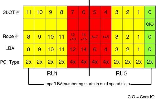
The IO cardcage on a Superdome is a 12-slot PCI cardcage. Other cell-based servers have a 6-slot PCI cardcage. The cardcage hosts both dual-speed and quad speed PCI cards. A traditional Superdome complex has eight dual-speed slots (64-bit, 33 MHz) and four quad-speed slots (64-bit, 66MHz). The new Integrity servers use PCI-X interfaces. This means that on an Integrity Superdome, we have eight quad-speed cards (64-bit PCI-X, 66MHz) and four eight-speed slots (64-bit PCI-X, 133MHz). The new Integrity servers use a new chipset for the IO subsystem (the REO chip is now known as a Grande chip, and the IO interface chips are now known as Mercury chips instead of Elroys). To make my diagrams easier to follow, I will refer to the original Superdome infrastructure where we have dual- and quad-speed slots as well as REO and Elroy chips. To translate Figures 2-13 and 2-14 to be appropriate for an Integrity server, you would replace Elroy with Mercury, 2x with 4x, and 4x with 8x. Otherwise, the ideas are the same.
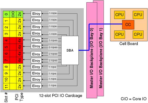
What is not evident is the effect a quad-speed card has on the HP-UX hardware path. This is where we introduce a little bit of HP-hardware-techno-speak; it's there to explain why the HP-UX hardware path looks a bit weird in comparison to the physical slot number in the IO cardcage. Let's look at a block diagram of what we are going to explain:
A cell that is connected to an IO cardcage communicates with the IO cardcage via a link from the Cell Controller to a single System Bus Adapter (SBA) chip located on the power board of the IO cardcage and routed via the Master IO backplane. The SBA supports up to 16 ropes (a rope being an HP name for an interface to a PCI card). The circuitry that communicates with the actual PCI card is known as an Elroy chip (newer Integrity servers use a Mercury chip to talk to a PCI-X interface). To communicate with a dual-speed interface, the Elroy uses a single rope. To communicate with a quad-speed interface, the Elroy requires two ropes. It is the rope number that is used as the Local Bus Address (LBA) in the HP-UX hardware path. At first this seems overly complicated, unnecessary, and rather confusing. We discuss it because we need to be able to locate a physical PCI card either via its Slot-ID or its HP-UX hardware path. We also need to be able to relate a Slot-ID to the appropriate HP-UX hardware path. It will become clear, honest!
The LBA on an Integrity server are derived in the same way. One of the reasons behind the numbering is that an SBA is made up of two Rope Units (RU0 and RU1). In the future, there is the potential to supply a 6-slot PCI cardcage for Superdome (we saw that four connectors are already there on the Master IO Backplane). A 6-slot IO cardcage only needs one Rope Unit, and we always start the rope/LBA numbering in the dual-speed slots. The way I try to visualize Figure 2-14 is that they have taken two 6-slot PCI cardcages and connected them by sticking the quad speeds slots back to back.
We can now discuss how this has an impact on the hardware addressing we see in our partitions.
Some of you may be wondering why we are spending so much time on hardware addressing. Is this really a job for commands such as ioscan? Yes, it is. However, once we have created a partition, we will need to boot the partition from install media to install the operating system. On a traditional server, we have a boot interface such as the Boot Console Handler (BCH), which is known as the Extensible Firmware Interface (EFI) on an Integrity server. At this interface, we have commands to search for potential boot devices. We can even search on the network for potential install servers:
Main Menu: Enter command or menu > sea lan install

Searching for potential boot device(s) - on Path 0/0/0/0
This may take several minutes.

To discontinue search, press any key (termination may not be immediate).


   Path#  Device Path (dec)  Device Path (mnem)  Device Type
   -----  -----------------  ------------------  -----------
   P0     0/0/0/0            lan.192.168.0.35   LAN Module


Main Menu: Enter command or menu >
On a Node Partition, we do not have a logical device known as lan at the boot interface. That's because there are two many permutations of physical hardware paths that would all need to be translated to the logical lan device. Consequently, we have to know the specific hardware address for our LAN cards and supply that address to the BCH search command. This is why we are spending so long discussing hardware paths and how to work them out by analyzing the content of your PCI cardcage.
Here's a quick list of how to work out a hardware path shown in Figure 2-15.
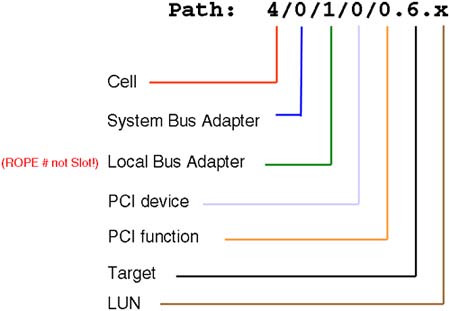
Here is a breakdown of the individual components of the Hardware Path:
Cell: This is the physical cell number where the device is located or connected.
SBA: For IO devices, e.g., interface cards, disks, and so on, the SBA is always 0, because a cell can only be physically connected to a single IO cardcage. If the device in question is a CPU, individual CPUs are numbered 10, 11, 12, and 13 on a traditional Superdome. On an Integrity Superdome, CPUs are numbered 120, 121, 122, and 123.
LBA: This is the rope/LBA number we saw in Figure 2-14.
PCI device: On a traditional Superdome, this number is always 0 (using Elroy chips). On an Integrity Superdome with PCI-X cards, this number is always 1 (using Mercury chips). It's a neat trick to establish which IO architecture we are using.
PCI Function: On a single function card, this is always 0. On a card such as dual-port Fire Channel card, each port has its own PCI Function number, 0 and 1.
Target: We are now into the device-specific part of the hardware path. This can be information such as SCSI target ID, Fibre Channel N-Port ID, and so on.
LUN: This is more device-specific information such as the SCSI LUN number.
A command that can help translate Slot-IDs into the corresponding HP-UX hardware paths is the rad -q command (olrad -q on an Integrity server):
root@uksd4 #rad -q
                                                                     Driver(s)
Slot        Path        Bus   Speed   Power   Occupied    Suspended   Capable
0-0-3-0     6/0/0       0     33      On      Yes         No          No
0-0-3-1     6/0/1/0     8     33      On      Yes         No          Yes
0-0-3-2     6/0/2/0     16    33      On      Yes         No          Yes
0-0-3-3     6/0/3/0     24    33      On      Yes         No          Yes
0-0-3-4     6/0/4/0     32    33      On      Yes         No          Yes
0-0-3-5     6/0/6/0     48    33      On      Yes         No          Yes
0-0-3-6     6/0/14/0    112   66      On      Yes         No          Yes
0-0-3-7     6/0/12/0    96    33      On      No          N/A         N/A
0-0-3-8     6/0/11/0    88    33      On      Yes         No          Yes
0-0-3-9     6/0/10/0    80    33      On      Yes         No          Yes
0-0-3-10    6/0/9/0     72    33      On      Yes         No          Yes
0-0-3-11    6/0/8/0     64    33      On      Yes         No          Yes
root@uksd4 #
Here we can see that cell 6 (the first component of the hardware path) is connected to IO cardcage in cabinet 0, IO Bay, IO connector 3 (0-0-3 in the Slot-ID). We can still use the ioscan command to find which types of cards are installed in these slots.
root@uksd4 #ioscan -fnkC processor
Class       I  H/W Path  Driver    S/W State H/W Type  Description
===================================================================
processor   0  6/10      processor CLAIMED   PROCESSOR Processor
processor   1  6/11      processor CLAIMED   PROCESSOR Processor
processor   2  6/12      processor CLAIMED   PROCESSOR Processor
processor   3  6/13      processor CLAIMED   PROCESSOR Processor
root@uksd4 #
root@uksd4 #ioscan -fnkH 6/0/8/0
Class     I  H/W Path       Driver S/W State   H/W Type     Description
======================================================================
ext_bus   7  6/0/8/0/0      c720 CLAIMED     INTERFACE    SCSI C87x Ultra Wide Differential
target   18  6/0/8/0/0.7    tgt  CLAIMED     DEVICE
ctl       7  6/0/8/0/0.7.0  sctl CLAIMED     DEVICE       Initiator
                           /dev/rscsi/c7t7d0
ext_bus   8  6/0/8/0/1      c720 CLAIMED     INTERFACE    SCSI C87x Ultra Wide Differential
target   19  6/0/8/0/1.7    tgt  CLAIMED     DEVICE
ctl       8  6/0/8/0/1.7.0  sctl CLAIMED     DEVICE       Initiator
                           /dev/rscsi/c8t7d0
root@uksd4 #
In the examples above, we can confirm that there are four CPUs within cell 6. We can also say that in slot 11 (LBA=8) we have a dual-port Ultra-Wide SCSI card (PCI Function 0 and 1).
We should perform some analysis of our configuration in order to establish the hardware paths of our LAN cards. Armed with this information, we can interact with the boot interface and perform a search on our LAN devices for potential install servers.
root@uksd4 #lanscan
Hardware Station        Crd Hdw   Net-Interface  NM  MAC       HP-DLPI DLPI
Path     Address        In# State NamePPA        ID  Type      Support Mjr#
6/0/0/1/0 0x001083FD9D57 0   UP    lan0 snap0     1   ETHER     Yes     119
6/0/2/0/0 0x00306E0C74FC 1   UP    lan1 snap1     2   ETHER     Yes     119
6/0/9/0/0 0x00306E0CA400 2   UP    lan2 snap2     3   ETHER     Yes     119
6/0/10/0/0 0x0060B0582B95 3   UP    lan3           4   FDDI      Yes     119
6/0/14/0/0 0x00306E0F09C8 4   UP    lan4 snap4     5   ETHER     Yes     119
root@uksd4 #
root@uksd4 #ioscan -fnkC lan
Class     I  H/W Path    Driver S/W State   H/W Type     Description
====================================================================
lan       0  6/0/0/1/0   btlan CLAIMED     INTERFACE    HP PCI 10/100Base-TX Core
                        /dev/diag/lan0  /dev/ether0     /dev/lan0
lan       1  6/0/2/0/0   btlan CLAIMED     INTERFACE    HP A5230A/B5509BA PCI 10/100Base-TX Addon
                        /dev/diag/lan1  /dev/ether1     /dev/lan1
lan       2  6/0/9/0/0   btlan CLAIMED     INTERFACE    HP A5230A/B5509BA PCI 10/100Base-TX Addon
                        /dev/diag/lan2  /dev/ether2     /dev/lan2
lan       3  6/0/10/0/0  fddi4 CLAIMED     INTERFACE    PCI FDDI Adapter HP A3739B
                        /dev/lan3
lan       4  6/0/14/0/0  gelan CLAIMED     INTERFACE    HP A4929A PCI 1000Base-T Adapter
root@uksd4 #
Obviously, to use commands like ioscan and rad, we need to have HP-UX already installed! It should be noted that just about every complex would come with preconfigured partitions and an operating system preinstalled within those partitions.
It should be noted that the new Integrity servers can display hardware paths using the Extensible Firmware Interface (EFI) numbering convention. See the ioscan –e command for more details.
At this point, we are ready to move on and look at managing/creating partitions. I have made the decision to create a new complex profile from scratch; in other words, I am going to create the Genesis Partition. Before doing so, I must ensure that I understand the High Availability and High Performance design criteria for creating partitions. I may also want to document the current partition configuration as seen from the HP-UX perspective. With the parstatus command below, I can see a one-liner for each configured partition in the complex:
root@uksd4 #parstatus -P
[Partition]
Par              # of  # of I/O
Num Status       Cells Chassis  Core cell  Partition Name (first 30 chars)
=== ============ ===== ======== ========== ===============================
 0  active         1      1     cab0,cell0 uksd1
 1  active         1      1     cab0,cell4 uksd2
 2  active         1      1     cab0,cell2 uksd3
 3  active         1      1     cab0,cell6 uksd4
root@uksd4 #
I can gain useful, detailed information pertaining to each partition using the parstatus command but targeting a particular partition:
root@uksd4 #parstatus -Vp 0
[Partition]
Partition Number       : 0
Partition Name         : uksd1
Status                 : active
IP address             : 0.0.0.0
Primary Boot Path      : 0/0/1/0/0.0.0
Alternate Boot Path    : 0/0/1/0/0.5.0
HA Alternate Boot Path : 0/0/1/0/0.6.0
PDC Revision           : 35.4
IODCH Version          : 5C70
CPU Speed              : 552 MHz
Core Cell              : cab0,cell0

[Cell]
                       CPU     Memory                                Use
                        OK/     (GB)                          Core    On
Hardware  Actual       Deconf/ OK/                           Cell    Next Par
Location  Usage        Max     Deconf    Connected To        Capable Boot Num
========= ============ ======= ========= =================== ======= ==== ===
cab0,cell0 active core  4/0/4    4.0/ 0.0 cab0,bay1,chassis3  yes     yes  0

[Chassis]
                                 Core Connected  Par
Hardware Location   Usage        IO   To         Num
=================== ============ ==== ========== ===
cab0,bay1,chassis3  active       yes  cab0,cell0 0

root@uksd4 #
I would normally list and store the detailed configuration for each partition before creating the Genesis Partition in case I wanted to reinstate the old configuration at some later data.
Notice that this is the first time we have been able to establish the speed of the processors within a cell; the PS command does not show you this. Sometimes, there is a sticker/badge on the cell board itself, but this can't always be relied on (you may have had several upgrades since then).
In order to create the Genesis Partition, I must shut down all active partitions in such a way that they will be halted and ready to accept a new complex profile. This is similar to the reboot-for-reconfig concept we mentioned earlier when we discussed making changes to the Complex Profile. The only difference here is that we are performing a halt-for-reconfig; in other words, each partition will be ready to accept a new Complex Profile but will not restart automatically. This requires two new options to the shutdown command:
-R: Shuts down the system to a ready-to-reconfig state and reboots automatically. This option is available only on systems that support hardware partitions.
-H: Shuts down the system to a ready-to-reconfig state and does not reboot. This option can be used only in combination with the -R option. This option is available only on systems that support hardware partitions.
In essence, when we create the Genesis Partition, all cells need to be in an Inactive state; otherwise, the process will fail. I am now going to run the shutdown –RH now command on all partitions.
The Genesis Partition gets its name from the biblical story of the beginning of time. In our case, the Genesis Partition is simply the first partition that is created. When we discussed designing a Complex Profile, we realized that when we have 16 cells, there are 65,536 possible cell combinations. Trying to create a complex profile from the GSP, which is a simple terminal-based interface, would be somewhat tiresome. Consequently, the Genesis Partition is simply a one-cell partition that allows us to boot a partition and install an operating system. The Genesis Partition is the only partition created on the GSP. All other partition configuration is performed via Partition Manager commands run from an operating system. Once we have created the Genesis Partition, we can boot the system from an install server and install HP-UX. From that initial operating system installation, we can create a new partition, and from there we can create other partitions as we see fit. After the initial installation is complete, the Genesis Partition is of no special significance. It is in no way more important than any other partition; partition 0 doesn't even have to exist.
In order to create the Genesis Partition, all cells must be inactive and shut down ready-for-reconfig. You will have to take my word for the fact that I have shut down all my partitions using the shutdown –RH now command:
root@uksd4 #shutdown -RH now

SHUTDOWN PROGRAM
11/07/03 22:33:07 GMT

Broadcast Message from root (console) Fri Nov 7 22:33:07...
SYSTEM BEING BROUGHT DOWN NOW ! ! !
We can check the status of the cells/partitions by using the VFP:
    GSP MAIN MENU:

         CO: Consoles
        VFP: Virtual Front Panel
         CM: Command Menu
         CL: Console Logs
         SL: Show chassis Logs
         HE: Help
          X: Exit Connection

GSP> vfp

    Partition VFP's available:

     #   Name
    ---  ----
     0)  uksd1
     1)  uksd2
     2)  uksd3
     3)  uksd4
     S)  System (all chassis codes)
     Q)  Quit

GSP:VFP> s

E indicates error since last boot
  #  Partition state               Activity
  -  ---------------               --------
  0  Cell(s) Booting:    677 Logs
  1  Cell(s) Booting:    716 Logs
  2  Cell(s) Booting:    685 Logs
  3  Cell(s) Booting:    276 Logs

GSP:VFP (^B to Quit) >
It may seem strange that the cells for each partition are trying to boot, but they aren't. When we look at an individual partition, we can see the actual state of the cells:
    GSP MAIN MENU:

         CO: Consoles
        VFP: Virtual Front Panel
         CM: Command Menu
         CL: Console Logs
         SL: Show chassis Logs
         HE: Help
          X: Exit Connection

GSP> vfp

    Partition VFP's available:

     #   Name
    ---  ----
     0)  uksd1
     1)  uksd2
     2)  uksd3
     3)  uksd4
     S)  System (all chassis codes)
     Q)  Quit

GSP:VFP> 0

E indicates error since last boot
     Partition 0  state            Activity
     ------------------            --------
     Cell(s) Booting:    677 Logs

  #  Cell state                    Activity
  -  ----------                    --------
  0  Boot Is Blocked (BIB)         Cell firmware                    677  Logs

GSP:VFP (^B to Quit) >
Only at this point (when all cells are inactive) can we proceed with creating the Genesis Partition.
If we attempt to create the Genesis Partition while partitions are active, it will fail. To create the Genesis Partition, we use the GSP CC command:
    GSP MAIN MENU:

         CO: Consoles
        VFP: Virtual Front Panel
         CM: Command Menu
         CL: Console Logs
         SL: Show chassis Logs
         HE: Help
          X: Exit Connection

GSP> cm
                Enter HE to get a list of available commands


GSP:CM> cc

This command allows you to change the complex profile.

WARNING: You must either shut down the OSs for reconfiguration or
         execute the RR (reset for reconfiguration) command for all
         partitions before executing this command.

    G - Build genesis complex profile
    L - Restore last complex profile
        Select profile to build or restore:
As you can see, the GSP is able to restore the previous incarnation of Complex Profile. We will choose option G (Build genesis complex profile):
GSP:CM> cc

This command allows you to change the complex profile.

WARNING: You must either shut down the OSs for reconfiguration or
         execute the RR (reset for reconfiguration) command for all
         partitions before executing this command.

    G - Build genesis complex profile
    L - Restore last complex profile
        Select profile to build or restore: g


Building a genesis complex profile will create a complex profile
consisting of one partition with a single cell.

Choose the cell to use.

    Enter cabinet number:
The initial questions relating to the creation of the Genesis Partition are relatively simple; the GSP only needs to know which single cell will be the initial cell that will form partition 0. This cell must be Core Cell capable; in other words, at least one CPU (preferably at least two), at least one Rank/Echelon of RAM (preferably at least two) connected to an IO cardcage that has a Core IO card installed in slot 0. If you know all this information, you can proceed with creating the Genesis Partition:
Choose the cell to use.

    Enter cabinet number: 0
    Enter slot number: 0

    Do you want to modify the complex profile? (Y/[N]) y

    -> The complex profile will be modified.
GSP:CM>
I have chosen to select cell 0 for partition 0. It is not important which cell forms the Genesis Partition, as long as it is Core Cell capable. The GSP will check that it meets the criteria we mentioned previously. Assuming that the cell passes those tests, the Genesis Partition has now been created. In total, all the tasks from issuing the CC command took approximately 10 seconds. This is the only partition configuration we can perform from the GSP. We can now view the resulting Complex Profile:
GSP:CM> cp

--------------------------------------------------------------------------------
Cabinet |   0    |   1    |   2    |   3    |   4    |   5    |   6    |   7
--------+--------+--------+--------+--------+--------+--------+--------+--------
 Slot   |01234567|01234567|01234567|01234567|01234567|01234567|01234567|01234567
--------+--------+--------+--------+--------+--------+--------+--------+--------
Part  0 |X.......|........|........|........|........|........|........|........

GSP:CM>
As you can see, we only have one partition with one cell as its only member. This cell is in the Boot-Is-Blocked (BIB) state. Essentially, when the cell(s) in a partition are in the BIB state, they are waiting for someone to give them a little nudge in order to start booting the operating system. There are reasons why a cell will remain in the BIB state; we talk about that later. To boot the partition, we use the GSP BO command:
GSP:CM> bo

This command boots the selected partition.


     #   Name
    ---  ----
     0)  Partition 0

    Select a partition number: 0

    Do you want to boot partition number 0? (Y/[N]) y

    -> The selected partition will be booted.
GSP:CM>
This is when it is ideal to have at least three of the screens we mentioned previously (Console, VFP, and Command Menu screens) in order to flip between the screens easily. We issue the BO command from the Command Menu screen, and then we want to monitor the boot-up of the partition from the VFP screen, and we interact with the boot-up of HP-UX from the Console screen. Here I have interacted with the boot-up of HP-UX in the Console screen:
GSP:CM> ma
GSP:CM>

    GSP MAIN MENU:

         CO: Consoles
        VFP: Virtual Front Panel
         CM: Command Menu
         CL: Console Logs
         SL: Show chassis Logs
         HE: Help
          X: Exit Connection

GSP> co

    Partitions available:

     #   Name
    ---  ----
     0)  Partition 0
     Q)  Quit

    Please select partition number: 0


        Connecting to Console: Partition 0


        (Use ^B to return to main menu.)

        [A few lines of context from the console log:]

- - - - - - - - - - - - - - - - - - - - - - - - - - - - - - -

     MFG menu                          Displays manufacturing commands

     DIsplay                           Redisplay the current menu
     HElp [<menu>|<command>]           Display help for menu or command
     REBOOT                            Restart Partition
     RECONFIGRESET                     Reset to allow Reconfig Complex Profile
----
Main Menu: Enter command or menu >

- - - - - - - - - - - - - - - - - - - - - - - - - - - - - - -

Main Menu: Enter command or menu >
Main Menu: Enter command or menu > main

---- Main Menu ----------------------------------------------------------

     Command                          Description
     -------                          -----------
     BOot [PRI|HAA|ALT|<path>]        Boot from specified path
     PAth [PRI|HAA|ALT] [<path>]      Display or modify a path
     SEArch [ALL|<cell>|<path>]       Search for boot devices
     ScRoll [ON|OFF]                  Display or change scrolling capability

     COnfiguration menu               Displays or sets boot values
     INformation menu                 Displays hardware information
     SERvice menu                     Displays service commands
     DeBug menu                       Displays debug commands
     MFG menu                         Displays manufacturing commands

     DIsplay                          Redisplay the current menu
     HElp [<menu>|<command>]          Display help for menu or command
     REBOOT                           Restart Partition
     RECONFIGRESET                    Reset to allow Reconfig Complex Profile
----
Main Menu: Enter command or menu >
As you can see, the interface looks similar to the BCH from a traditional HP-UX server. Apart from some slight changes during the initial Power-On Self Test phase, the boot-up of a partition is extremely similar to the boot-up of a traditional server. Returning to the BCH interface, we can check whether any of the old boot paths were retained.
Main Menu: Enter command or menu > path

Primary Boot Path:  0/0/1/0/0.6
0/0/1/0/0.6    (hex)

HA Alternate Boot Path:  0/0/1/0/0.6
0/0/1/0/0.6    (hex)

Alternate Boot Path:  0/0/1/0/0.5
0/0/1/0/0.5    (hex)

Main Menu: Enter command or menu >
As you can see, they have taken some default values that mean nothing to us. At this stage, we have two choices: (1) we can reinstall HP-UX, or (2) we can boot the original HP-UX, which is still located on the original root disk. Changing the complex profile has not changed the fundamental operating system stored on disk; it is still on disk and will quite happily run with this new partition configuration. If we think about it, it is akin to shutting down a traditional server adding/removing some CPU, RAM, and/or IO cards and booting the server again. HP-UX will discover the hardware during the IO discovery phase and use what it finds. Some devices may be missing if the previous partition had additional IO cardcages. This may affect the activation of volume groups, activating LAN cards and other hardware related configuration, but in essence we can simply use the operating system that was installed previously on the disk attached to the IO cardcage for this cell.
If there is no operating system available, we will have to install it. In such a situation, we will need access to a boot device. Here we can see the SEARCH command from the BCH.
Main Menu: Enter command or menu > search

Searching for potential boot device(s)
This may take several minutes.

To discontinue search, press any key (termination may not be immediate).


   Path#  Device Path (dec)                      Device Type
   -----  -----------------                      -----------
   P0     0/0/1/0/0.1                            Random access media
   P1     0/0/1/0/0.0                            Random access media
          0/0/8/0/0.0                            Fibre Channel Protocol
   P2     0/0/11/0/0.3                           Sequential access media
   P3     0/0/11/0/0.1                           Random access media
          0/0/14/0/0.0                           Fibre Channel Protocol


Main Menu: Enter command or menu >
This all looks quite familiar. If I had a local device such as a CD/DVD drive and I were going to install HP-UX from that device, I would simply boot from one of the devices listed above. Let's try to SEARCH for an install server attached to our LAN. The traditional method to do this would be with the BCH command SEARCH LAN INSTALL.
Main Menu: Enter command or menu > search lan install

ERROR: Unknown device

Search Table has been cleared

Main Menu: Enter command or menu >
As you can see, a Node Partition has no concept of the logical device known as LAN. It is too much for the boot interface in a server complex to be able to traverse every possible cell in our partition looking for a LAN card. Consequently, I need to have done my homework earlier and know the hardware path to a LAN card connected to a network where an Install server is located. My only other option is to use the Information Menu, which can tell me which cards are installed in which slots:
Main Menu: Enter command or menu > in

---- Information Menu -------------------------------------------------------

     Command                           Description
     -------                           -----------
     ALL [<cell>]                   Display all of the information
     BootINfo                       Display boot-related information
     CAche [<cell>]                 Display cache information
     ChipRevisions [<cell>]         Display revisions of major VLSI
     ComplexID                      Display Complex information
     FabricInfo                     Display Fabric information
     FRU [<cell>] [CPU|MEM]         Display FRU information
     FwrVersion [<cell>]            Display version for PDC, ICM, and Complex
     IO [<cell>]                    Display I/O interface information
     MEmory [<cell>]                Display memory information
     PRocessor [<cell>]             Display processor information

     BOot [PRI|HAA|ALT|<path>]      Boot from specified path
     DIsplay                        Redisplay the current menu
     HElp [<command>]               Display help for specified command
     REBOOT                         Restart Partition
     RECONFIGRESET                  Reset to allow Reconfig Complex Profile
     MAin                           Return to Main Menu
----
Information Menu: Enter command >
Information Menu: Enter command > io 0

I/O CHASSIS INFORMATION

   Cell Info             I/O Chassis Info

Cell   Cab/Slot        Cab    Bay   Chassis
----   --------        ---    ---   -------
  0      0/0            0      1      3


I/O MODULE INFORMATION

                    Path            Slot   Rope                         IODC
Type                (dec)            #      #     HVERSION   SVERSION   Vers
----                -----           ----   ----   --------   --------   ----
System Bus Adapter  0/0                            0x8040     0x0c18    0x00
Local Bus Adapter   0/0/0            0       0     0x7820     0x0a18    0x00
Local Bus Adapter   0/0/1            1       1     0x7820     0x0a18    0x00
Local Bus Adapter   0/0/2            2       2     0x7820     0x0a18    0x00
Local Bus Adapter   0/0/3            3       3     0x7820     0x0a18    0x00
Local Bus Adapter   0/0/4            4       4     0x7820     0x0a18    0x00
Local Bus Adapter   0/0/6            5       6     0x7820     0x0a18    0x00
Local Bus Adapter   0/0/8            11      8     0x7820     0x0a18    0x00
Local Bus Adapter   0/0/9            10      9     0x7820     0x0a18    0x00
Local Bus Adapter   0/0/10           9      10     0x7820     0x0a18    0x00
Local Bus Adapter   0/0/11           8      11     0x7820     0x0a18    0x00
Local Bus Adapter   0/0/12           7      12     0x7820     0x0a18    0x00
Local Bus Adapter   0/0/14           6      14     0x7820     0x0a18    0x00


PCI DEVICE INFORMATION

                            Path             Bus    Slot      Vendor   Device
Description                 (dec)             #      #          Id       Id
-----------                 -----            ---   ------     ------   ------
Comm. serial cntlr          0/0/0/0/0        0       0        0x103c   0x1048
Ethernet cntlr              0/0/0/1/0        0       0        0x1011   0x0019
SCSI bus cntlr              0/0/1/0/0        8       1        0x1000   0x000c
SCSI bus cntlr              0/0/3/0/0        24      3        0x1000   0x000f
SCSI bus cntlr              0/0/3/0/1        24      3        0x1000   0x000f
Fibre channel               0/0/8/0/0        64     11        0x103c   0x1028
Ethernet cntlr              0/0/9/0/0        72     10        0x1011   0x0019
SCSI bus cntlr              0/0/10/0/0       80      9        0x1000   0x000f
SCSI bus cntlr              0/0/10/0/1       80      9        0x1000   0x000f
SCSI bus cntlr              0/0/11/0/0       88      8        0x1000   0x000f
Fibre channel               0/0/14/0/0       112     6        0x103c   0x1028


Information Menu: Enter command >
I can see that I have a LAN card at Hardware Path 0/0/0/1/0. I can attempt to boot from it:
Main Menu: Enter command or menu > boot 0/0/0/1/0

 BCH Directed Boot Path: 0/0/0/1/0.0


 Do you wish to stop at the ISL prompt prior to booting? (y/n) >> n

Initializing boot Device.


Boot IO Dependent Code (IODC) Revision 2
...
NOTE:
       The console firmware terminal type is currently set to "vt100". If you
       are using any other type of terminal you will see "garbage" on the
       screen following this message.
       If this is the case, you will need to either change the terminal type
       set in the firmware via GSP (if your GSP firmware version supports
       this feature), or change your terminal emulation to match the
       firmware. In either case you will need to restart if your terminal and
       the firmware terminal type do not match.
       Press the 'b' key if you want to reboot now.


                        Welcome to Ignite-UX!

 Use the <tab> key to navigate between fields, and the arrow keys
 within fields. Use the <return/enter> key to select an item.
 Use the <return/enter> or <space-bar> to pop-up a choices list. If the
 menus are not clear, select the "Help" item for more information.

 Hardware Summary:         System Model: 9000/800/SD32000
 +---------------------+----------------+-------------------+ [ Scan Again  ]
 | Disks: 3 ( 101.7GB) |  Floppies: 0   | LAN cards:   2    |
 | CD/DVDs:        1   |  Tapes:    1   | Memory:    4096Mb |
 | Graphics Ports: 0   |  IO Buses: 8   | CPUs:        4    | [ H/W Details ]
 +---------------------+----------------+-------------------+

                       [      Install HP-UX       ]

                       [   Run a Recovery Shell   ]

                       [    Advanced Options      ]

          [  Reboot  ]                              [  Help  ]
As we can see, we have now found an Ignite/UX install server from which we can boot and install the operating system. Once the operating system is installed and we have customized it as we see fit, HP-UX will boot. That would be the time to add additional partitions and modify the existing partition, if that is appropriate. The additional partition-related tasks are not performed from the GSP but from the operating system we have just installed.
Before we leave this section, let me say just a few words regarding the Information Menu in the BCH. This is a good place to gather additional information and consolidate your existing cell-related device information, e.g., CPU and memory:
Information Menu: Enter command > me 0

CELL MEMORY INFORMATION

Memory Information for Cell:  0   Cab/Slot:  0/ 0

     ---- DIMM A ----   ---- DIMM B ----   ---- DIMM C ---  ---- DIMM D ----
      DIMM  Current      DIMM  Current      DIMM  Current    DIMM  Current
Rank  Size  Status       Size  Status       Size  Status     Size  Status
---- ------ ----------  ------ ----------  ------ --------  ------ ----------
  0   512MB Active       512MB Active       512MB Active     512MB Active
  1   512MB Active       512MB Active       512MB Active     512MB Active
  2    ---                ---                ---              ---
  3    ---                ---                ---              ---
  4    ---                ---                ---              ---
  5    ---                ---                ---              ---
  6    ---                ---                ---              ---
  7    ---                ---                ---              ---

       Cell Total Memory:     4096 MB
      Cell Active Memory:     4096 MB
Cell Deconfigured Memory:        0 MB

* status is scheduled to change on next boot.

Information Menu: Enter command >
Here, I am looking at my current memory compliment confirming my use of four 512MB DIMMs per Rank.
Information Menu: Enter command > pr

PROCESSOR INFORMATION

        Cab/                                                     Processor
 Cell   Slot   CPU    Speed     HVERSION   SVERSION   CVERSION     State
 ----   ----   ---   --------   --------   --------   --------  --------------
   0    0/0     0     552 MHz    0x5c70     0x0491     0x0301    Active
                1     552 MHz    0x5c70     0x0491     0x0301    Idle
                2     552 MHz    0x5c70     0x0491     0x0301    Idle
                3     552 MHz    0x5c70     0x0491     0x0301    Idle

             Partition Total Cells: 1
        Partition Total Processors: 4
       Partition Active Processors: 4
 Partition Deconfigured Processors: 0

Information Menu: Enter command >
I will let you explore other Information Menu commands in your own time.
Once HP-UX has installed and rebooted, you may want to check the state of you Boot Paths. The install process should have set your Primary Boot Path to be the disk you specified as your root disk during the installation.
root@uksd1 #setboot
Primary bootpath : 0/0/1/0/0.0.0
Alternate bootpath : 0/0/1/0/0.5.0

Autoboot is OFF (disabled)
Autosearch is OFF (disabled)

Note: The interpretation of Autoboot and Autosearch has changed for
systems that support hardware partitions. Please refer to the manpage.
root@uksd1 #
Notice that Autoboot and Autosearch are both OFF. You can also see the Note regarding the change to the meaning of these parameters. We can still modify these parameters via the setboot command.
root@uksd1 #setboot -b on
root@uksd1 #setboot -s on
root@uksd1 #setboot
Primary bootpath : 0/0/1/0/0.0.0
Alternate bootpath : 0/0/1/0/0.5.0

Autoboot is ON (enabled)
Autosearch is ON (enabled)

Note: The interpretation of Autoboot and Autosearch has changed for
systems that support hardware partitions. Please refer to the manpage.
root@uksd1 #
However, there are two new concepts related to booting that are new with Node Partitionable servers. This first new concept is in relation to the number of Boot Paths available to us. Instead of having only a Primary (PRI) and an Alternate (ALT) Boot Path, we have an additional Boot Path—a High Availability Alternate (HAA). By default, this device is searched second in the list of boot devices. To set the HAA Boot Path, we need to use either the BCH PATH HAA <path> command or the Partition Manager parmodify command.
root@uksd1 #parstatus -w
The local partition number is 0.
root@uksd1 #parstatus -Vp 0
[Partition]
Partition Number       : 0
Partition Name         : Partition 0
Status                 : active
IP address             : 0.0.0.0
Primary Boot Path      : 0/0/1/0/0.0.0
Alternate Boot Path    : 0/0/1/0/0.5.0
HA Alternate Boot Path : 0/0/1/0/0.6.0
PDC Revision           : 35.4
IODCH Version          : 5C70
CPU Speed              : 552 MHz
Core Cell              : cab0,cell0

[Cell]
                        CPU     Memory                              Use
                        OK/     (GB)                        Core    On
Hardware   Actual       Deconf/ OK/                         Cell    Next Par
Location   Usage        Max     Deconf    Connected To      Capable Boot Num
========== ============ ======= ========= ================= ======= ==== ===
cab0,cell0 active core  4/0/4    4.0/ 0.0 cab0,bay1,chassis3  yes     yes  0


[Chassis]
                                 Core Connected  Par
Hardware Location   Usage        IO   To         Num
=================== ============ ==== ========== ===
cab0,bay1,chassis3  active       yes  cab0,cell0 0

root@uksd1 #
root@uksd1 #parmodify -p 0 -s 0/0/1/0/0.1.0
Command succeeded.
root@uksd1 #parstatus -Vp 0
[Partition]
Partition Number       : 0
Partition Name         : Partition 0
Status                 : active
IP address             : 0.0.0.0
Primary Boot Path      : 0/0/1/0/0.0.0
Alternate Boot Path    : 0/0/1/0/0.5.0
HA Alternate Boot Path : 0/0/1/0/0.1.0
PDC Revision           : 35.4
IODCH Version          : 5C70
CPU Speed              : 552 MHz
Core Cell              : cab0,cell0

[Cell]
                        CPU     Memory                                Use
                        OK/     (GB)                          Core    On
Hardware   Actual       Deconf/ OK/                           Cell    Next Par
Location   Usage        Max     Deconf    Connected To        Capable Boot Num
========== ============ ======= ========= =================== ======= ==== ===
cab0,cell0 active core  4/0/4    4.0/ 0.0 cab0,bay1,chassis3  yes     yes  0

[Chassis]
                                 Core Connected  Par
Hardware Location   Usage        IO   To         Num
=================== ============ ==== ========== ===
cab0,bay1,chassis3  active       yes  cab0,cell0 0

root@uksd1 #
To set the Alternate Boot Path with parmodify, we would use the –t <path> option.
root@uksd1 #ioscan -fnkC tape
Class     I  H/W Path        Driver S/W State   H/W Type     Description
========================================================================
tape      3  0/0/11/0/0.3.0  stape CLAIMED     DEVICE       HP      C1537A
                            /dev/rmt/3m            /dev/rmt/c6t3d0BESTn
                            /dev/rmt/3mb           /dev/rmt/c6t3d0BESTnb
                            /dev/rmt/3mn           /dev/rmt/c6t3d0DDS
                            /dev/rmt/3mnb          /dev/rmt/c6t3d0DDSb
                            /dev/rmt/c6t3d0BEST    /dev/rmt/c6t3d0DDSn
                            /dev/rmt/c6t3d0BESTb   /dev/rmt/c6t3d0DDSnb
root@uksd1 #parmodify -p 0 -s 0/0/11/0/0.3.0
Command succeeded.
root@uksd1 #parstatus -Vp 0
[Partition]
Partition Number       : 0
Partition Name         : Partition 0
Status                 : active
IP address             : 0.0.0.0
Primary Boot Path      : 0/0/1/0/0.0.0
Alternate Boot Path    : 0/0/1/0/0.5.0
HA Alternate Boot Path : 0/0/11/0/0.3.0
PDC Revision           : 35.4
IODCH Version          : 5C70
CPU Speed              : 552 MHz
Core Cell              : cab0,cell0

[Cell]
                        CPU     Memory                                Use
                        OK/     (GB)                          Core    On
Hardware   Actual       Deconf/ OK/                           Cell    Next Par
Location   Usage        Max     Deconf    Connected To        Capable Boot Num
========== ============ ======= ========= =================== ======= ==== ===
cab0,cell0 active core  4/0/4    4.0/ 0.0 cab0,bay1,chassis3  yes     yes  0

[Chassis]
                                 Core Connected  Par
Hardware Location   Usage        IO   To         Num
=================== ============ ==== ========== ===
cab0,bay1,chassis3  active       yes  cab0,cell0 0

root@uksd1 #
Here's how I remember the options to parmodify:
Primary = Boot =
-b <path>HA Alternate = Second =
-s <path>Alternate = Third =
-t <path>
The second new concept is related to the behavior of the search algorithm when searching the three available boot devices. This is known as PATHFLAGS. The PATHFLAGS affect how the boot interface interprets the three boot paths available to it. Remember, the three boot paths in order are:
Primary (PRI)
High-Availability Alternate (HAA)
Alternate (ALT)
By default, the boot interface will go to the next boot path if the current path fails to boot the operating system. The PATHFLAGS can change this behavior. A PATHFLAG is a numeric value associated with each boot path. The available PATHFLAGs are:
0: Go to BCH; if this path is accepted, stop at the Boot Console Handler.
1: Boot from this path; if unsuccessful, go to BCH.
2: Boot from this path; if unsuccessful, go to the next path (default).
3: Skip this path, and go to the next path.
The only place to directly set/modify the PATHFLAGS is from the BCH Configuration screen. If this is the first time you have experienced this, you will need to reboot HP-UX in order to interact with BCH:
Main Menu: Enter command or menu > co


---- Configuration Menu -----------------------------------------------------

    Command                           Description
    -------                           -----------
    BootID [<cell>[<proc>[<bootid>]]] Display or set Boot Identifier
    BootTimer [0-200]                 Seconds allowed for boot attempt
    CEllConfig [<cell>] [ON|OFF]      Config/Deconfig cell
    COreCell [<choice> <cell>]        Display or set core cell
    CPUconfig [<cell>[<cpu>[ON|OFF]]] Config/Deconfig processor
    DataPrefetch [ENABLE|DISABLE]     Display or set data prefetch behavior
    DEfault                           Set the Partition to predefined values
    FastBoot [test][RUN|SKIP]         Display or set boot tests execution
    KGMemory [<value>]                Display or set KGMemory requirement
    PathFlags [PRI|HAA|ALT] [<value>] Display or set Boot Path Flags
    PD [<name>]                       Display or set Partition name values
    ResTart [ON|OFF]                  Set Partition Restart Policy
    TIme [cn:yr:mo:dy:hr:mn:[ss]]     Read or set the real time clock
    BOot [PRI|HAA|ALT|<path>]         Boot from specified path
    DIsplay                           Redisplay the current menu
    HElp [<command>]                  Display help for specified command
    REBOOT                            Restart Partition
    RECONFIGRESET                     Reset to allow Reconfig Complex Profile
    MAin                              Return to Main Menu
----
Configuration Menu: Enter command > Configuration Menu: Enter command > pf

     Primary Boot Path Action
          Boot Actions:  Boot from this path.
                         If unsuccessful, go to next path.

HA Alternate Boot Path Action
          Boot Actions:  Go to BCH.

   Alternate Boot Path Action
          Boot Actions:  Go to BCH.

Configuration Menu: Enter command >
On a preconfigured server complex, the PATHFLAGS for all three Boot Paths should be 2 (Boot from this path; if unsuccessful, go to the next path). To change a path, we use the PF command for each Boot Path:
Configuration Menu: Enter command > pf pri 2

     Primary Boot Path Action
          Boot Actions:  Boot from this path.
                         If unsuccessful, go to next path.

Configuration Menu: Enter command > pf haa 2

HA Alternate Boot Path Action
          Boot Actions:  Boot from this path.
                         If unsuccessful, go to next path.

Configuration Menu: Enter command > pf alt 2

   Alternate Boot Path Action
          Boot Actions:  Boot from this path.
                         If unsuccessful, go to next path.

Configuration Menu: Enter command > pf

     Primary Boot Path Action
          Boot Actions:  Boot from this path.
                         If unsuccessful, go to next path.

HA Alternate Boot Path Action
          Boot Actions:  Boot from this path.
                         If unsuccessful, go to next path.

   Alternate Boot Path Action
          Boot Actions:  Boot from this path.
                         If unsuccessful, go to next path.

Configuration Menu: Enter command >
In some instances it may be appropriate to change the PATHFLAGS for a particular Boot Path, e.g., due to a hardware failure or testing, where you don't want to change the actual Boot Paths themselves.
Before we look at the Partition Manager software, we should discuss some important concepts regarding the state of cells during the initial boot of a partition. This discussion will help to explain the need for certain options when adding, removing and modifying cells in a partition.
When we power-on a cell, or a cabinet, or the entire complex through the GSP PE (Power Enable) command, each cell goes through a sequence of tests before booting within a partition configuration, if appropriate. As soon as the cabinet 48V power has stabilized, a hardware register for each cell is set. This register dictates the behavior of the Boot Inhibit Bit (BIB) and is commonly referred to as Boot-Is-Blocked. BIB is designed to stop a cell from booting until all appropriate checks have been made to ensure that the cell is functioning properly. Each cell will go through its Power-On Self Test (POST), which has various steps such as CPU self tests, Memory self tests, IO Discovery, and Fabric Discovery. During this initial phase, the cells are considered INACTIVE. The amount of cell-related hardware will determine how long the POST will take to complete. We can monitor the POST from the VFP screen within the GSP.
    GSP MAIN MENU:

         CO: Consoles
        VFP: Virtual Front Panel
         CM: Command Menu
         CL: Console Logs
         SL: Show chassis Logs
         HE: Help
          X: Exit Connection

GSP> vfp

    Partition VFP's available:

     #   Name
    ---  ----
     0)  Partition 0
     S)  System (all chassis codes)
     Q)  Quit

GSP:VFP> 0

Eindicates error since last boot

     Partition 0  state            Activity

     ------------------            --------

     Cell(s) Booting:    238 Logs


  #  Cell state                    Activity

  -  ----------                    --------

  0  Early CPU selftest            Processor test               238  Logs


GSP:VFP (^B to Quit) >
The POST goes through various phases. (The Logs can be viewed via the GSP SL command. Unless we see an error indicated by the letter E beside the cell number, the Logs are simply Activity Logs.) Once the cell has finished its POST, it reports its hardware configuration to the GSP and is left spinning on BIB. A cell will spin on BIB, waiting for other cells in its partition configuration to finish their POST before being allowed to boot the partition. This makes sense, because we can't have a partition boot while a cell is still performing a POST. While a cell is performing its POST, details of cell-related hardware are not available to the GSP or other administrative commands such as Partition Manager. Once all cells have reach BIB, the GSP will supply the cells with the current version of the Complex Profile, release BIB, and allow the partition to boot. As soon as BIB is cleared the cell is considered to be active. At this stage, the cells are said to have reached partition rendezvous. If a cell does not get to a BIB state within 10 minutes of the initial POST, the GSP will clear BIB for the remaining cells and allow them to boot. This avoids the situation of a partition being blocked due to the failure of a single cell. At this point, the cells coordinate their activities in order to choose a Core Cell, which will proceed to boot the PDC/BCH. This is explained in Figure 2-16.
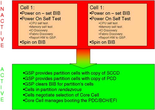
A cell will remain in a BIB state due to the following reasons:
The cell has not passed its POST and has some hardware error. This is indicated by the letter
Ebeside the cell number in the VFP. An investigation of theChassis Logs(via the GSPSLcommand) would reveal anyError Logs.Logsare time stamped and any newError Logsshould be reported to HP for further investigation.The use-on-next-boot flag has been set to NO for this cell. This is a specific partition configuration. We should not see this when creating the Genesis Partition.
The cell has an incoherent Complex Profile. This normally indicates some form of hardware error whereby the Complex Profile held in NVRAM has become corrupted. This should be reported to HP for further investigation.
Now that we have a Genesis Partition and understand the state of cells during the initial boot of a partition, we can now look at adding/modifying partitions via the Partition Manager software.
The Partition Manager software is installed by default with HP-UX (even on non-partitionable servers). There are essentially three interfaces: a GUI, a CLUI, and a Web-based GUI. To start the Web-based GUI, we need to ensure that the Apache Web server is started (this is the ObAM-Apache Web server on HP-UX 11.11).
root@uksd1 #vi /etc/rc.config.d/webadmin
#!/sbin/sh
# $Header: /kahlua_src/web/server/etc/webadmin 72.1 1999/09/16 03:51:04 lancer Exp $
# WebAdmin application server configuration.
#
# WEBADMIN:             Set to 1 to start the WebAdmin application server.
#
WEBADMIN=1
root@uksd1 #/sbin/init.d/webadmin start
/usr/obam/server/bin/apachectl start: httpd started
root@uksd1 #
We can now navigate to the URL http://<server>:1188/parmgr and interface with the web-based GUI (the URL for HP-UX 11.23 is http://<server>:50000/parmgr).
The first time we interact with the Web-based GUI, we need to navigate to the “Configure Browser” hot-link and follow the instructions to install a plug-in into our browser. Once complete, we can interface with the GUI directly. The interface behaves in exactly the same way as the host-based GUI. Here's the main screen from running the host-based GUI (/opt/parmgr/bin/parmgr):
Like other ObAM interfaces, if we don't select an Object, the Action we can perform is limited to Add/Create. From the Main Screen, we can navigate via “Partition”–“Create Partition” where we will be asked to fill in a series of dialog boxes and then to confirm the process of Creating a partition. Interacting with the screens isn't rocket science. Consequently, I will demonstrate creating additional partitions by using the CLUI (Command Line User Interface … isn't that a terrible acronym?!). To create a partition, we use a command called parcreate. To display the status of existing partitions, we use the command parstatus. I won't be giving out any prizes for guessing the command to modify or remove an existing partition.
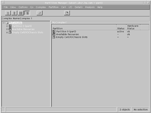
Before creating a new partition, we should remember all the design rules we encountered in Section 2.1 regarding the choice of cells to meet both High Availability and High Performance criteria; remember the nifty-54 diagram? We should also remember the minimum requirements for a partition:
One cell with at least one CPU
One Rank/Echelon of RAM
One IO cardcage with a Core IO card in slot 0
Remember, these are the ABSOLUTE minimums. We can use the parstatus command to query which cells (-AC) and which IO cardcages (-AI) are currently available.
root@uksd1 #parstatus -AC
[Cell]
                        CPU     Memory                               Use
                        OK/     (GB)                         Core    On
Hardware   Actual       Deconf/ OK/                          Cell    Next Par
Location   Usage        Max     Deconf    Connected To       Capable Boot Num
========== ============ ======= ========= ================== ======= ==== ===
cab0,cell1 absent       -       -         -                   -       -    -
cab0,cell2 inactive     4/0/4    4.0/ 0.0 cab0,bay1,chassis1  yes     -    -
cab0,cell3 absent       -       -         -                   -       -    -
cab0,cell4 inactive     4/0/4    4.0/ 0.0 cab0,bay0,chassis1  yes     -    -
cab0,cell5 absent       -       -         -                   -       -    -
cab0,cell6 inactive     4/0/4    4.0/ 0.0 cab0,bay0,chassis3  yes     -    -
cab0,cell7 absent       -       -         -                   -       -    -

root@uksd1 #
root@uksd1 #parstatus -AI
[Chassis]
                                 Core Connected  Par
Hardware Location   Usage        IO   To         Num
=================== ============ ==== ========== ===
cab0,bay0,chassis0  absent       -    -          -
cab0,bay0,chassis1  inactive     yes  cab0,cell4 -
cab0,bay0,chassis2  absent       -    -          -
cab0,bay0,chassis3  inactive     yes  cab0,cell6 -
cab0,bay1,chassis0  absent       -    -          -
cab0,bay1,chassis1  inactive     yes  cab0,cell2 -
cab0,bay1,chassis2  absent       -    -          -

root@uksd1 #
When we create the partition, we may decide to configure the Boot Paths at the same time. As we mentioned in Section 2.2.2.1: Boot Actions, partition servers have three potential boot paths:
Primary boot path: This is the first boot path we will attempt to boot from. We can use the
parcreate/parmodify(the–p <path>option),setboot, or BCH/EFI interface to configure this boot path. This device is normally our root/boot disk.High Availability Alternative: This is the second boot path we will attempt to boot from. Feedback from customers made HP realize that having only two potential boot devices was not enough. To change this boot path, we need to use either the
parcreate/parmodify(the–s <path>option) commands or use the BCH/EFI interface. Thesetbootcommand knows nothing about this boot path! This device is normally a mirror disk of our root/boot device.Alternate boot path: This is the last device we attempt to boot from. We can use the
parcreate/parmodify(the–t <path>option),setboot, or BCH/EFI interface to configure this boot path. This is normally a tape or CD/DVD device, although it could be a third mirror copy if we have configured three-way mirroring.
If we know all this information now, it makes configuring the partition much easier. Finally, we need to give the partition a name. The numbering of partitions is performed automatically be the Partition Manager commands. A default name of “Partition 0” is sufficient but not very descriptive. The partition name has nothing to do with the system hostname. The partition name can be 64 characters in length and can contain alphanumeric characters including dashes, underscores, dots, and spaces. I can't say that I have come across a consistent naming convention for partition names. Some customers will use the hostname as a partition name to avoid confusion. Other customers use a long, descriptive name, including some reference to the application/organization using that particular partition. Changes to the partition name are immediate. Here, I am changing the name of my current partition to uksd1:
root@uksd1 #parstatus -P
[Partition]
Par              # of  # of I/O
Num Status       Cells Chassis  Core cell  Partition Name (first 30 chars)
=== ============ ===== ======== ========== ===============================
 0  active         1      1     cab0,cell0 Partition 0
root@uksd1 #parmodify -p 0 -P uksd1
Command succeeded.
root@uksd1 #parstatus -P
[Partition]
Par              # of  # of I/O
Num Status       Cells Chassis  Core cell  Partition Name (first 30 chars)
=== ============ ===== ======== ========== ===============================
 0  active         1      1     cab0,cell0 uksd1
root@uksd1 #
We will now create a new partition.
This new partition will be partition 1 and will be called uksd2. We will include cell 4 as the only cell in the partition and will detail the boot paths as appropriate (this would require that I know the hardware paths to appropriate devices). Here goes:
root@uksd1 #parcreate -P uksd2 -c 0/4::: -b 4/0/6/0/0.0.0 -t 4/0/6/0/0.8.0
Partition Created. The partition number is: 1
root@uksd1 #
root@uksd1 #parstatus -Vp 1
[Partition]
Partition Number       : 1
Partition Name         : uksd2
Status                 : inactive
IP address             : 0.0.0.0
Primary Boot Path      : 4/0/6/0/0.0.0
Alternate Boot Path    : 0/0/0/0/0.0.0
HA Alternate Boot Path : 4/0/6/0/0.8.0
PDC Revision           : 35.4
IODCH Version          : 5C70
CPU Speed              : 552 MHz
Core Cell              : ?

[Cell]
                        CPU     Memory                               Use
                        OK/     (GB)                         Core    On
Hardware   Actual       Deconf/ OK/                          Cell    Next Par
Location   Usage        Max     Deconf    Connected To       Capable Boot Num
========== ============ ======= ========= ================== ======= ==== ===
cab0,cell4 inactive     4/0/4    4.0/ 0.0 cab0,bay0,chassis1  yes     yes  1

[Chassis]
                                 Core Connected  Par
Hardware Location   Usage        IO   To         Num
=================== ============ ==== ========== ===
cab0,bay0,chassis1  inactive     yes  cab0,cell4 1

root@uksd1 #
root@uksd1 #parstatus -P
[Partition]
Par              # of  # of I/O
Num Status       Cells Chassis  Core cell  Partition Name (first 30 chars)
=== ============ ===== ======== ========== ===============================
 0  active         1      1     cab0,cell0 uksd1
 1  inactive       1      1     ?          uksd2
root@uksd1 #
As you can see, the partition was created but as yet remains inactive. The options to parcreate may need a little explaining.
-c 0/4::: : We are creating a partition using the
–coption to refer to a cell. The0/4specifies cabinet0, cell4. The remaining options are required even though I have not specified them. The options, when specified, would be:0/4:base:y:ri
base: This is the cell type. Base cells are the only type of cell currently supported. This is the default and as such does not need to be specified. Theparstatuscommand reports cells as either base or core. A core cell is the cell providing console capability. A core cell is still configured as a base cell withparcreate.y: This is the use-on-next-boot flag. This option determines whether this cell will participate in the next boot of this partition. Because we have just created this partition, I think it is a good idea that we use the cell. The default isyand as such does not need to be specified.ri: This defines memory reuse after a failure. Theristands for reuse interleave, which means that we will interleave memory. This is the only supported option and as such does not need to be specified.There is a final option I have not listed because it is only supported on servers using the hp sx1000 chipset running HP-UX 11.23. The final option,
:clm, specifies the percentage (rounded to a multiple of 12.5 percent, or a multiple of 25 percent if cell memory is less than 4GB), or an absolute value (rounded to the nearest 0.5GB) for Cell Local Memory. There is a proportion of memory within this cell that will not be interleaved. Some applications that frequently access large data sets may perform better when accessing memory that is guaranteed to be in the same cell, hence avoiding any latency accessing memory across the Cell Controller/XBC interface.
-b 4/0/6/0/0.0.0: This is to be my Primary Boot Path for this partition.
-t 4/0/6/0/0.8.0: This is to be my Alternate Boot Path for this partition. I have purposefully excluded my High Availability Alternate as part of this demonstration. Normally, I would want to configure all three Boot Paths.
There is an option to specify an IP address for a partition (-I <IP address>). This option is still valid but is not used by any diagnostic or GSP utilities to communicate directly with the partition at any time. If you are going to specify a partition IP address, it is suggested you set it to be the same as the main IP address of the server.
When we look at the state of the new partition via the VFP, we see that it is not currently booted.
    GSP MAIN MENU:

         CO: Consoles
        VFP: Virtual Front Panel
         CM: Command Menu
         CL: Console Logs
         SL: Show chassis Logs
         HE: Help
          X: Exit Connection

GSP> vfp

    Partition VFP's available:

     #   Name
    ---  ----
     0)  uksd1
     1)  uksd2
     S)  System (all chassis codes)
     Q)  Quit

GSP:VFP> 1
E indicates error since last boot
     Partition 1  state            Activity
     ------------------            --------
     Cell(s) Booting:    716 Logs

  #  Cell state                    Activity
  -  ----------                    --------
  4  Boot Is Blocked (BIB)         Cell firmware                    716  Logs

GSP:VFP (^B to Quit) >
We could have used the –B option to parcreate, which would effectively initiate a GSP BO command as soon as the partition was created. As such, we need to log in to the GSP Command Menu and issue the BO command ourselves (again having the three screens Command Menu, Console, and VFP is quite useful during this phase of creating our partitions).
    GSP MAIN MENU:

         CO: Consoles
        VFP: Virtual Front Panel
         CM: Command Menu
         CL: Console Logs
         SL: Show chassis Logs
         HE: Help
          X: Exit Connection

GSP> cm


                Enter HE to get a list of available commands


GSP:CM> bo

This command boots the selected partition.


     #   Name
    ---  ----
     0)  uksd1
     1)  uksd2

    Select a partition number: 1

    Do you want to boot partition number 1? (Y/[N]) y

    -> The selected partition will be booted.
GSP:CM>
Again, we will need to interact with the attempted boot-up of HP-UX within that partition (via the Console window). I am going to take this opportunity to set up the PATHFLAGS for this partition.
GSP:CM> ma
GSP:CM>

    GSP MAIN MENU:

         CO: Consoles
        VFP: Virtual Front Panel
         CM: Command Menu
         CL: Console Logs
         SL: Show chassis Logs
         HE: Help
          X: Exit Connection

GSP> co

    Partitions available:

     #   Name
    ---  ----
     0)  uksd1
     1)  uksd2
     Q)  Quit

    Please select partition number: 1


        Connecting to Console: uksd2

        (Use ^B to return to main menu.)

        [A few lines of context from the console log:]

- - - - - - - - - - - - - - - - - - - - - - - - - - - - - - -

    MFG menu                          Displays manufacturing commands
    DIsplay                           Redisplay the current menu
    HElp [<menu>|<command>]           Display help for menu or command
    REBOOT                            Restart Partition
    RECONFIGRESET                     Reset to allow Reconfig Complex Profile
----
Main Menu: Enter command or menu >

- - - - - - - - - - - - - - - - - - - - - - - - - - - - - - -

Main Menu: Enter command or menu >
Main Menu: Enter command or menu > pa

     Primary Boot Path:  4/0/6/0/0.0
                         4/0/6/0/0.0    (hex)

HA Alternate Boot Path:  4/0/6/0/0.8
                         4/0/6/0/0.8    (hex)

   Alternate Boot Path:  0/0/0/0/0.0
                         0/0/0/0/0.0    (hex)

Main Menu: Enter command or menu >
Main Menu: Enter command or menu > co


--- Configuration Menu ------------------------------------------------------

    Command                           Description
    -------                           -----------
    BootID [<cell>[<proc>[<bootid>]]] Display or set Boot Identifier
    BootTimer [0-200]                 Seconds allowed for boot attempt
    CEllConfig [<cell>] [ON|OFF]      Config/Deconfig cell
    COreCell [<choice> <cell>]        Display or set core cell
    CPUconfig [<cell>[<cpu>[ON|OFF]]] Config/Deconfig processor
    DataPrefetch [ENABLE|DISABLE]     Display or set data prefetch behavior
    DEfault                           Set the Partition to predefined values
    FastBoot [test][RUN|SKIP]         Display or set boot tests execution
    KGMemory [<value>]                Display or set KGMemory requirement
    PathFlags [PRI|HAA|ALT] [<value>] Display or set Boot Path Flags
    PD [<name>]                       Display or set Partition name values
    ResTart [ON|OFF]                  Set Partition Restart Policy
    TIme [cn:yr:mo:dy:hr:mn:[ss]]     Read or set the real time clock

    BOot [PRI|HAA|ALT|<path>]         Boot from specified path
    DIsplay                           Redisplay the current menu
    HElp [<command>]                  Display help for specified command
    REBOOT                            Restart Partition
    RECONFIGRESET                     Reset to allow Reconfig Complex Profile
    MAin                              Return to Main Menu
----
Configuration Menu: Enter command > pf

     Primary Boot Path Action
          Boot Actions:  Skip this path.
                         Go to next path.

HA Alternate Boot Path Action
          Boot Actions:  Skip this path.
                         Go to next path.

   Alternate Boot Path Action
          Boot Actions:  Skip this path.
                         Go to BCH.

Configuration Menu: Enter command > pf pri 2

     Primary Boot Path Action
          Boot Actions:  Boot from this path.
                         If unsuccessful, go to next path.

Configuration Menu: Enter command > pf haa 2

HA Alternate Boot Path Action
          Boot Actions:  Boot from this path.
                         If unsuccessful, go to next path.

Configuration Menu: Enter command > pf alt 2

   Alternate Boot Path Action
          Boot Actions:  Boot from this path.
                         If unsuccessful, go to next path.

Configuration Menu: Enter command > pf

     Primary Boot Path Action
          Boot Actions:  Boot from this path.
                         If unsuccessful, go to next path.

HA Alternate Boot Path Action
          Boot Actions:  Boot from this path.
                         If unsuccessful, go to next path.

   Alternate Boot Path Action
          Boot Actions:  Boot from this path.
                         If unsuccessful, go to next path.

Configuration Menu: Enter command >
Configuration Menu: Enter command > ma

---- Main Menu --------------------------------------------------------------

    Command                           Description
    -------                           -----------
    BOot [PRI|HAA|ALT|<path>]         Boot from specified path
    PAth [PRI|HAA|ALT] [<path>]       Display or modify a path
    SEArch [ALL|<cell>|<path>]        Search for boot devices
    ScRoll [ON|OFF]                   Display or change scrolling capability

    COnfiguration menu                Displays or sets boot values
    INformation menu                  Displays hardware information
    SERvice menu                      Displays service commands
    DeBug menu                        Displays debug commands
    MFG menu                          Displays manufacturing commands

    DIsplay                           Redisplay the current menu
    HElp [<menu>|<command>]           Display help for menu or command
    REBOOT                            Restart Partition
    RECONFIGRESET                     Reset to allow Reconfig Complex Profile
----
Main Menu: Enter command or menu > bo pri

     Primary Boot Path:  4/0/6/0/0.0


 Do you wish to stop at the ISL prompt prior to booting? (y/n) >> n

Initializing boot Device.


Boot IO Dependent Code (IODC) Revision 0


Boot Path Initialized.


HARD Booted.

ISL Revision A.00.43  Apr 12, 2000

ISL booting  hpux

Boot
: disk(4/0/6/0/0.0.0.0.0.0.0;0)/stand/vmunix

9007104 + 1712216 + 1300392 start 0x41d72e8
In this instance, there is an operating system on the Primary Boot Path for that partition, and I am simply going to let HP-UX boot. Otherwise, we will need to interact with the boot interface and install HP-UX, as before.
I will create a third partition called uksd3. This partition will contain two cells, cell 2 and cell 6. Cell 2 will be our first Core Cell choice. Cell 6 will be our Core Cell alternative. Core cell choices are configured using the –r option to parcreate/parmodify. If our Core Cell fails, HP-UX will currently panic with an HPMC. This is where the goal of High Availability comes into play. If we have been clever and dual-pathed all our devices via both IO cardcages and specified a Core Cell alternate, our partition will be able to boot with the existing resources. Again, we will specify our three Boot Paths at this time. We will also use the –B option to boot the new partition as soon as it has been created:
root@uksd1 #parcreate -P uksd3 -c 0/2::: -c 0/6::: -b 2/0/1/0/0.0.0 -s 2/0/4/0/0/0.8.0 -t 2/0/4/0/0.8.0 -r 0/2 -r 0/6 -B
Partition Created. The partition number is: 2
root@uksd1 #
root@uksd1 #parstatus -P
[Partition]
Par              # of  # of I/O
Num Status       Cells Chassis  Core cell  Partition Name (first 30 chars)
=== ============ ===== ======== ========== ===============================
 0  active         1      1     cab0,cell0 uksd1
 1  active         1      1     cab0,cell4 uksd2
 2  active         2      2     cab0,cell2 uksd3
root@uksd1 #
root@uksd1 #parstatus -Vp 2
[Partition]
Partition Number       : 2
Partition Name         : uksd3
Status                 : active
IP address             : 0.0.0.0
Primary Boot Path      : 2/0/1/0/0.0.0
Alternate Boot Path    : 2/0/4/0/0.8.0
HA Alternate Boot Path : 2/0/4/0/0.8.0
PDC Revision           : 35.4
IODCH Version          : 5C70
CPU Speed              : 552 MHz
Core Cell              : cab0,cell2
Core Cell Alternate [1]: cab0,cell2
Core Cell Alternate [2]: cab0,cell6

[Cell]
                        CPU     Memory                               Use
                        OK/     (GB)                         Core    On
Hardware   Actual       Deconf/ OK/                          Cell    Next Par
Location   Usage        Max     Deconf    Connected To       Capable Boot Num
========== ============ ======= ========= ================== ======= ==== ===
cab0,cell2 active core  4/0/4    4.0/ 0.0 cab0,bay1,chassis1  yes     yes  2
cab0,cell6 active base  4/0/4    4.0/ 0.0 cab0,bay0,chassis3  yes     yes  2

[Chassis]
                                 Core Connected  Par
Hardware Location   Usage        IO   To         Num
=================== ============ ==== ========== ===
cab0,bay1,chassis1  active       yes  cab0,cell2 2
cab0,bay0,chassis3  active       yes  cab0,cell6 2

root@uksd1 #
We have used the –B option to parcreate. This will release both cells from BIB and allow the partition to boot. I will still have to interact with the BCH to see whether the partition has booted past the BCH.
    GSP MAIN MENU:

         CO: Consoles
        VFP: Virtual Front Panel
         CM: Command Menu
         CL: Console Logs
         SL: Show chassis Logs
         HE: Help
          X: Exit Connection

GSP> co

    Partitions available:

     #   Name
    ---  ----
     0)  uksd1
     1)  uksd2
     2)  uksd3
     Q)  Quit

    Please select partition number: 2


        Connecting to Console: uksd3

        (Use ^B to return to main menu.)

        [A few lines of context from the console log:]

- - - - - - - - - - - - - - - - - - - - - - - - - - - - - - -

    MFG menu                          Displays manufacturing commands

    DIsplay                           Redisplay the current menu
    HElp [<menu>|<command>]           Display help for menu or command
    REBOOT                            Restart Partition
    RECONFIGRESET                     Reset to allow Reconfig Complex Profile
----
Main Menu: Enter command or menu >

- - - - - - - - - - - - - - - - - - - - - - - - - - - - - - -

Main Menu: Enter command or menu > path

     Primary Boot Path:  2/0/1/0/0.0
                         2/0/1/0/0.0    (hex)

HA Alternate Boot Path:  2/0/4/0/0.8
                         2/0/4/0/0.8    (hex)

   Alternate Boot Path:  2/0/4/0/0.8
                         2/0/4/0/0.8    (hex)

Main Menu: Enter command or menu >
I will set up the PATHFLAGS again and attempt to boot the partition from the existing operating system. I will not list these steps because you have seen them already. We now discuss modifying existing partitions.
We now have three partitions created. When we want to modify an existing partition, we can use the Partition Manager commands from any partition in the complex. On HP-UX 11.11, there is little security as to who is allowed to make these changes. The only criteria are (1) you have the authority to run the Partition Manager commands, i.e., the root user, and (2) you are not trying to change the assignment of active cells on a remote partition (a remote partition is a partition within your complex but a different partition to the one you are currently logged into). Beginning with HP-UX 11.23, servers that utilize the hp sx1000 chipset can utilize a feature called IPMI (Intelligent Platform Management Interface). Be sure to check whether your server is capable of using this feature. By using the GSP SO command, we can set the IPMI password. This means that commands such as parstatus and parmodify will work only for our own local partition. If we want to manage remote partitions in our complex (in fact, we can even manage remote partitions in other IPMI-enabled complexes), we need to use the –g <IPMI password> option to the Partition Manager commands. There is a second part to the IPMI configuration; we need to enable restricted partition management. This is accomplished by the GSP PARPERM command. Be default, partition management is unrestricted as it is in HP-UX 11.11. When restricted, we can manage only our own local partition unless we supply the IPMI password.
Because we are using HP-UX 11.11, partition management is unrestricted; in other words, as root, we can modify any partition in our complex. This can be easily demonstrated by changing the name of a remote partition.
root@uksd1 #parstatus -w
The local partition number is 0.
root@uksd1 #parstatus -P
[Partition]
Par              # of  # of I/O
Num Status       Cells Chassis  Core cell  Partition Name (first 30 chars)
=== ============ ===== ======== ========== ===============================
 0  active         1      1     cab0,cell0 uksd1
 1  active         1      1     cab0,cell4 uksd2
 2  active         2      2     cab0,cell2 uksd3
root@uksd1 #parmodify -p 2 -P "Finance Department"
Command succeeded.
root@uksd1 #parstatus -P
[Partition]
Par              # of  # of I/O
Num Status       Cells Chassis  Core cell  Partition Name (first 30 chars)
=== ============ ===== ======== ========== ===============================
 0  active         1      1     cab0,cell0 uksd1
 1  active         1      1     cab0,cell4 uksd2
 2  active         2      2     cab0,cell2 Finance Department
root@uksd1 #
Changes like these do not change the usage or assignment of cells. In such cases, the changes take immediate effect. When we alter the usage or the assignment of cell, we will need to reboot the partition(s) involved.
When we remove an active cell from an active partition, we must reboot the affected partition ready-to-reconfig in order to load the most up-to-date version of the Complex Profile to all affected cells. This can be achieved only when a cell is in an inactive state; currently we do not have Online Addition and Replacement (OLA/R) for cells or cell components. In fact, whenever we make ANY cell assignment changes, we must reboot the partition(s) ready-to-reconfigl in order to flush the current active Complex Profile from NVRAM of the partitions cells and load the new Complex Profile provided by the GSP.
Let's look at an example where we remove cell 6 from partition 2, uksd3. We use the –d <cell> option to delete the cell from the partition.
root@uksd1 #parstatus -w
The local partition number is 0.
root@uksd1 #parmodify -p 2 -d 0/6 -B
Cell 6 is active.
Error: Partition 2 is active.
Cannot reboot a non-local active partition.
Command Aborted.
root@uksd1 #
The most important option here is the –B option. Without this option, the cells would remain in the BIB state, because the GSP cannot push out a new version of the SCCD until all affected cells are inactive. The process can be summarized as follows:
The Partition Manager executes the appropriate
parmodifycommand to change the partition.The
parmodifycommand generates a new SCCD and sends it to the GSP.The GSP waits for the affected cell(s) to become inactive.
The
parmodifycommand ends and displays a message that a reboot-for-reconfig is necessary.The administrator performs a reboot-for-reconfig of the affected partition.
The reboot process ends with a reset-for-reconfig done on each cell in the partition.
Each cell has BIB set, performs POST, and spins on BIB.
When the GSP sees that all affected cells have BIB set, it pushes out the new SCCD.
If the GSP was told to boot the partition (the –B option), then it waits until all of the cells (according to the new SCCD) are at BIB and then boots the partition.
Principally, it is the requirement for all affected cells to be inactive before a new SCCD can be pushed out that requires us to use the –B option to parmodify.
I can now run the parmodify on partition 2 and reboot the partition using the –R option to the shutdown command.
root @uksd3 #parstatus -w
The local partition number is 2.
root @uksd3 #parmodify -p 2 -d 0/6 -B
Cell 6 is active.
Use shutdown -R to shutdown the system to ready for reconfig state.
Command succeeded.
root @uksd3 #
root @uksd3 #shutdown -R now

SHUTDOWN PROGRAM
11/08/03 03:47:37 GMT

Broadcast Message from root (console) Sat Nov  8 03:47:37...
SYSTEM BEING BROUGHT DOWN NOW ! ! !
...
Warning:  Stable Complex Configuration Data lock
error. Sub pushing out new stable.

It is not possible to signal the GSP to reboot this
partition once it has been shutdown. The partition
might still automatically reboot, but if it doesn't
then use the GSP Command Menu to manually boot the
partition.
sync'ing disks (0 buffers to flush):
0 buffers not flushed
0 buffers still dirty

Closing open logical volumes...
Done

Boot device reset done.


Cells has been reset and are ready for reconfiguration (Boot Is Blocked (BIB) is set).

 Please check Virtual Front Panel (VFP) for reset status.
We should monitor the boot-up of this partition via the VFP screen within the GSP.
    GSP MAIN MENU:

         CO: Consoles
        VFP: Virtual Front Panel
         CM: Command Menu
         CL: Console Logs
         SL: Show chassis Logs
         HE: Help
          X: Exit Connection

GSP> vfp

    Partition VFP's available:

     #   Name
    ---  ----
     0)  uksd1
     1)  uksd2
     2)  Finance Department
     S)  System (all chassis codes)
     Q)  Quit

GSP:VFP> 2

E indicates error since last boot
     Partition 2  state            Activity
     ------------------            --------
     HPUX Launch                   Processor system initialization  114  Logs

  #  Cell state                    Activity
  -  ----------                    --------
  2  Cell has joined partition

GSP:VFP (^B to Quit) >
The only issue with this scenario is that the SCCD is in a pending state while the reboot of the partition takes place. The GSP will lock the SCCD until that change has taken effect. This means that any other administrator on the complex will not be able to make changes to the SCCD until I reboot-for-reconfig. There is currently no way to determine which changes are pending; we can identify simply that there is a change pending. If an administrator receives an error message indicating that the Partition Manager cannot obtain a lock on the SCCD, all the administrator can do is use the parunlock command (the GUI interface will prompt the administrator to unlock the SCCD via an appropriate dialog box). This will remove the pending change to the SCCD; in other words, my changes to cell assignment will be lost!
To avoid the problem of having a pending change in the SCCD, it would be best if we perform partition configuration on inactive partitions whose cells are ready to receive a new SCCD; they were shutdown-for-reconfig (shutdown –RH). In this way, the cells are inactive and the new SCCD can be immediately pushed out to the cells. The drawback with this is that the process can be seen to take longer, involves more than one partition, and may require the administrator to manually boot the affected partition from the GSP. If you choose this route, you will not see the problem with having to unlock the Complex Profile, but you will have more commands to type and more screens to interact with.
A third alternative is possible and I find this slightly sinister because it doesn't require a reboot-for-reconfig for the partition that loses a cell, although it does require at least a normal reboot. The configuration change revolves around the use of the use-on-next-boot flag, which we can be set on a cell-by-cell basis. If we change the use-on-next-boot flag to NO (=n), this does not affect the cell-assignment configuration, i.e., it does not affect the SCCD (the use-on-next-boot flag is part of the PCD). Changes to the PCD take effect immediately. We saw this earlier with the change of a partition name. As we have seen, we can effect changes to the PCD from any partition in the complex because this does not affect cell assignment. This means that the administrator of partition 0 could change the use-on-next-boot flag for a cell in partition 2. The administrator of partition 0 is relying on the fact that partition 2 is going to perform at least a normal reboot (he overheard the administrators of partition 2 saying that the need to reboot is due to some kernel configuration changes). Once the (normal) reboot has taken place, the affected cell is left inactive, even though it is still a member of the partition. Because the cell is inactive, the administrator of partition 0 can remove the inactive cell from partition 2 and use it for himself. This also assumes that the administrators of partition 2 don't notice the fact that they have half as many CPUs and half as much RAM. I will return cell 6 to partition 2 and demonstrate this for you:
root@uksd1 #parstatus -w
The local partition number is 0.
root@uksd1 #parstatus -P
[Partition]
Par              # of  # of I/O
Num Status       Cells Chassis  Core cell  Partition Name (first 30 chars)
=== ============ ===== ======== ========== ===============================
 0  active         1      1     cab0,cell0 uksd1
 1  active         1      1     cab0,cell4 uksd2
 2  active         2      2     cab0,cell6 Finance Department
root@uksd1 #
root@uksd1 #parstatus -Vp 2
[Partition]
Partition Number       : 2
Partition Name         : Finance Department
Status                 : active
IP address             : 0.0.0.0
Primary Boot Path      : 2/0/1/0/0.0.0
Alternate Boot Path    : 2/0/4/0/0.8.0
HA Alternate Boot Path : 2/0/4/0/0.8.0
PDC Revision           : 35.4
IODCH Version          : 5C70
CPU Speed              : 552 MHz
Core Cell              : cab0,cell6
Core Cell Alternate [1]: cab0,cell6

[Cell]
                        CPU     Memory                               Use
                        OK/     (GB)                         Core    On
Hardware   Actual       Deconf/ OK/                          Cell    Next Par
Location   Usage        Max     Deconf    Connected To       Capable Boot Num
========== ============ ======= ========= ================== ======= ==== ===
cab0,cell2 active base  4/0/4    4.0/ 0.0 cab0,bay1,chassis1  yes     yes  2
cab0,cell6 active core  4/0/4    4.0/ 0.0 cab0,bay0,chassis3  yes     yes  2

[Chassis]
                                 Core Connected  Par
Hardware Location   Usage        IO   To         Num
=================== ============ ==== ========== ===
cab0,bay1,chassis1  active       yes  cab0,cell2 2
cab0,bay0,chassis3  active       yes  cab0,cell6 2

root@uksd1 #
Now we change the use-on-next-boot flag from a remote partition.
root@uksd1 #parstatus -w
The local partition number is 0.
root@uksd1 #parmodify -p 2 -m 0/6::n:
Command succeeded.
root@uksd1 #
root@uksd1 #parstatus -Vp 2
[Partition]
Partition Number       : 2
Partition Name         : Finance Department
Status                 : active
IP address             : 0.0.0.0
Primary Boot Path      : 2/0/1/0/0.0.0
Alternate Boot Path    : 2/0/4/0/0.8.0
HA Alternate Boot Path : 2/0/4/0/0.8.0
PDC Revision           : 35.4
IODCH Version          : 5C70
CPU Speed              : 552 MHz
Core Cell              : cab0,cell6
Core Cell Alternate [1]: cab0,cell6

[Cell]
                        CPU     Memory                               Use
                        OK/     (GB)                         Core    On
Hardware   Actual       Deconf/ OK/                          Cell    Next Par
Location   Usage        Max     Deconf    Connected To       Capable Boot Num
========== ============ ======= ========= ================== ======= ==== ===
cab0,cell2 active base  4/0/4    4.0/ 0.0 cab0,bay1,chassis1  yes     yes  2
cab0,cell6 active core  4/0/4    4.0/ 0.0 cab0,bay0,chassis3  yes     no   2

[Chassis]
                                 Core Connected  Par
Hardware Location   Usage        IO   To         Num
=================== ============ ==== ========== ===
cab0,bay1,chassis1  active       yes  cab0,cell2 2
cab0,bay0,chassis3  active       yes  cab0,cell6 2

root@uksd1 #
Although this change has been immediate in the PCD, cell 6 will remain active until the next reboot. In this example, the administrator of partition 0 knows partition 2 will reboot later on that day to effect the kernel configuration changes. In such a situation, the administrator of one partition has adversely affected the configuration of a partition used by another application/department/company. With the advent of the hp sx1000 chipset and the use if IPMI, this situation can be avoided.
We will now perform a normal reboot of partition 2 to demonstrate how the use-on-next-boot flag affects the partition:
root @uksd3 #parstatus -w
The local partition number is 2.
root @uksd3 #shutdown -r now

SHUTDOWN PROGRAM
11/08/03 04:17:40 GMT

Broadcast Message from root (console) Sat Nov  8 04:17:40...
SYSTEM BEING BROUGHT DOWN NOW ! ! !
If the administrator of partition 2 was in any way wary of other administrators on the complex he should monitor his partition booting, via the VFP:
    GSP MAIN MENU:

         CO: Consoles
        VFP: Virtual Front Panel
         CM: Command Menu
         CL: Console Logs
         SL: Show chassis Logs
         HE: Help
          X: Exit Connection

GSP> vfp

    Partition VFP's available:

     #   Name
    ---  ----
     0)  uksd1
     1)  uksd2
     2)  Finance Department
     S)  System (all chassis codes)
     Q)  Quit

GSP:VFP> 2

E indicates error since last boot
     Partition 2  state            Activity
     ------------------            --------
     HPUX heartbeat: *

  #  Cell state                    Activity
  -  ----------                    --------
  2  Cell has joined partition
  6  Boot Is Blocked (BIB)         Cell firmware                    837  Logs

GSP:VFP (^B to Quit) >
With the use-on-next-boot flag set to NO, we can see cell 6 is said to be spinning on BIB. Once partition 2 has rebooted, we can see that cell 6 is now inactive:
root @uksd3 #parstatus -w
The local partition number is 2.
root @uksd3 #parstatus -Vp 2
[Partition]
Partition Number       : 2
Partition Name         : Finance Department
Status                 : active
IP address             : 0.0.0.0
Primary Boot Path      : 2/0/1/0/0.0.0
Alternate Boot Path    : 2/0/4/0/0.8.0
HA Alternate Boot Path : 2/0/4/0/0.8.0
PDC Revision           : 35.4
IODCH Version          : 5C70
CPU Speed              : 552 MHz
Core Cell              : cab0,cell2
Core Cell Alternate [1]: cab0,cell6

[Cell]
                        CPU     Memory                               Use
                        OK/     (GB)                         Core    On
Hardware   Actual       Deconf/ OK/                          Cell    Next Par
Location   Usage        Max     Deconf    Connected To       Capable Boot Num
========== ============ ======= ========= ================== ======= ==== ===
cab0,cell2 active core  4/0/4    4.0/ 0.0 cab0,bay1,chassis1  yes     yes  2
cab0,cell6 inactive     4/0/4    4.0/ 0.0 cab0,bay0,chassis3  yes     no   2

[Chassis]
                                 Core Connected  Par
Hardware Location   Usage        IO   To         Num
=================== ============ ==== ========== ===
cab0,bay1,chassis1  active       yes  cab0,cell2 2
cab0,bay0,chassis3  inactive     yes  cab0,cell6 2

root @uksd3 #
root @uksd3 #ioscan -fnkC processor
Class       I  H/W Path  Driver    S/W State H/W Type  Description
===================================================================
processor   0  2/10      processor CLAIMED   PROCESSOR Processor
processor   1  2/11      processor CLAIMED   PROCESSOR Processor
processor   2  2/12      processor CLAIMED   PROCESSOR Processor
processor   3  2/13      processor CLAIMED   PROCESSOR Processor
root @uksd3 #dmesg | grep Physical
    Physical: 4186112 Kbytes, lockable: 3223188 Kbytes, available: 3702780 Kbytes
root @uksd3 #
The administrator of partition 0 can now remove the inactive cell 6 from partition 2 in preparation for adding it to his own partition.
root@uksd1 #parstatus -w
The local partition number is 0.
root@uksd1 #parmodify -p 2 -d 0/6
Command succeeded.
root@uksd1 #parstatus -Vp 2
[Partition]
Partition Number       : 2
Partition Name         : Finance Department
Status                 : active
IP address             : 0.0.0.0
Primary Boot Path      : 2/0/1/0/0.0.0
Alternate Boot Path    : 2/0/4/0/0.8.0
HA Alternate Boot Path : 2/0/4/0/0.8.0
PDC Revision           : 35.4
IODCH Version          : 5C70
CPU Speed              : 552 MHz
Core Cell              : cab0,cell2

[Cell]
                        CPU     Memory                               Use
                        OK/     (GB)                         Core    On
Hardware   Actual       Deconf/ OK/                          Cell    Next Par
Location   Usage        Max     Deconf    Connected To       Capable Boot Num
========== ============ ======= ========= ================== ======= ==== ===
cab0,cell2 active core  4/0/4    4.0/ 0.0 cab0,bay1,chassis1  yes     yes  2

[Chassis]
                                 Core Connected  Par
Hardware Location   Usage        IO   To         Num
=================== ============ ==== ========== ===
cab0,bay1,chassis1  active       yes  cab0,cell2 2

root@uksd1 #
root@uksd1 #parstatus -AC
[Cell]
                        CPU     Memory                               Use
                        OK/     (GB)                         Core    On
Hardware   Actual       Deconf/ OK/                          Cell    Next Par
Location   Usage        Max     Deconf    Connected To       Capable Boot Num
========== ============ ======= ========= ================== ======= ==== ===
cab0,cell1 absent       -       -         -                   -       -    -
cab0,cell3 absent       -       -         -                   -       -    -
cab0,cell5 absent       -       -         -                   -       -    -
cab0,cell6 inactive     4/0/4    4.0/ 0.0 cab0,bay0,chassis3  yes     -    -
cab0,cell7 absent       -       -         -                   -       -    -

root@uksd1 #
The administrator for partition 0 can now add this cell to their partition configuration. As I mentioned previously, I view this situation as somewhat sinister. Be sure that you understand the implications of using and not using IPMI to control access to partition configuration changes.
Adding a cell to a partition requires that cell to be inactive. As such, the task is relatively simple. We just identify the inactive cell and use parmodify to add it to our partition.
root@uksd1 #parstatus -AC
[Cell]
                        CPU     Memory                               Use
                        OK/     (GB)                         Core    On
Hardware   Actual       Deconf/ OK/                          Cell    Next Par
Location   Usage        Max     Deconf    Connected To       Capable Boot Num
========== ============ ======= ========= ================== ======= ==== ===
cab0,cell1 absent       -       -         -                   -       -    -
cab0,cell3 absent       -       -         -                   -       -    -
cab0,cell5 absent       -       -         -                   -       -    -
cab0,cell6 inactive     4/0/4    4.0/ 0.0 cab0,bay0,chassis3  yes     -    -
cab0,cell7 absent       -       -         -                   -       -    -

root@uksd1 #
root@uksd1 #parmodify -p 0 -a 0/6:::

In order to activate any cell that has been newly added,
reboot the partition with the -R option.
Command succeeded.
root@uksd1 #
Notice that I didn't use the –B option to parmodify. Because the affected cell was inactive, the new SCCD can be pushed out to that cell immediately. Consequently, to implement the change, we can simply perform a reboot-for-reconfig. The fact that we don't need to use the –B option to parmodify is a subtle difference but an important one.
root@uksd1 #shutdown –R -y now

SHUTDOWN PROGRAM
11/08/03 04:43:01 GMT

Broadcast Message from root (console) Sat Nov  8 04:43:01...
SYSTEM BEING BROUGHT DOWN NOW ! ! !
We should monitor the boot-up of this partition, as always via the VFP screen within the GSP.
To delete a partition, one of two possibilities must exist:
The partition is inactive. In such a situation, we can delete an inactive, remote partition.
The partition is active. If the partition is active, we can only delete the partition if the partition is local. We need to use the
–Foption toparremoveto delete an active, local partition. To instigate the change, we must perform a reboot-for reconfig.
Obviously, it is a good idea to inform your user community that their server (partition) will no longer be available after it is deleted:
root @uksd3 #parstatus -P
[Partition]
Par              # of  # of I/O
Num Status       Cells Chassis  Core cell  Partition Name (first 30 chars)
=== ============ ===== ======== ========== ===============================
 0  active         2      2     cab0,cell0 uksd1
 1  active         1      1     cab0,cell4 uksd2
 2  active         1      1     cab0,cell2 Finance Department
root @uksd3 #
root @uksd3 #parstatus -w
The local partition number is 2.
root @uksd3 #parremove -F -p 1
Error: Can not remove non-local active partition 1.
Command failed.
root @uksd3 #
As you can see from the above, Partition Manager has detected that we are trying to remove an active, remote partition and has produced an appropriate error message.
We can initiate the first stage of removing our own local partition, even though it is active:
root @uksd3 #parstatus -w
The local partition number is 2.
root @uksd3 #
root @uksd3 #parremove -F -p 2
Use "shutdown -R -H" to shutdown the partition.
The partition deletion will be effective only after the shutdown.
root @uksd3 #
All we need to do is to halt-to-reconfig to complete this change. Afterward, we will have to free unassigned, inactive cells.
There are other commands that we can issue from HP-UX, the GSP, and the BCH/EFI interface that are related to booting a partition. We can categorize these tasks as follows:
Reboot/halt a partition
Reboot-for-reconfig a partition
Reset a partition
TOC a partition
Boot actions
Powering off components
Some of these are trivial, but we will cover them, if only for completeness.
We still have the traditional ways of rebooting and halting a partition; the shutdown and reboot commands work in exactly the same way.
root @uksd3 #reboot -h
Shutdown at 04:54 (in 0 minutes)

        *** FINAL System shutdown message from root@uksd3 ***

System going down IMMEDIATELY
The main difference here is that if you halt a partition, there isn't a partition-reset-button anywhere. We do not use the power switch on the front of the cabinet except to power-off the entire cabinet. When a partition is halted, we can view an appropriate message on the system console.
Closing open logical volumes...
Done
Boot device reset done.


System has halted
OK to turn off power or reset system
UNLESS "WAIT for UPS to turn off power" message was printed above
At this stage, in order to restart the partition, we would use the GSP BO command.
We have looked at this scenario a number of times in respect of the shutdown command. The options –R and –H also apply to the reboot command. Obviously, we all know that the reboot command does not run the shutdown scripts and should be used only when the system is in a quiescent state, i.e., single-user mode.
If we are in a situation where we have forgotten to use the –R option to shutdown/reboot, any pending changes to the SCCD will not be pushed out by the GSP and the partition will reboot with the same Complex Profile as before the reboot. We don't necessarily want the partition to fully boot up in order to run another shutdown/reboot –R command. In this instance, we can interrupt the boot-up of the partition, stopping the partition at the BCH/EFI interface. From the BCH/EFI prompt, we can issue the RECONFIGRESET command:
---- Main Menu --------------------------------------------------------------

    Command                           Description
    -------                           -----------
    BOot [PRI|HAA|ALT|<path>]         Boot from specified path
    PAth [PRI|HAA|ALT] [<path>]       Display or modify a path
    SEArch [ALL|<cell>|<path>]        Search for boot devices
    ScRoll [ON|OFF]                   Display or change scrolling capability

    COnfiguration menu                Displays or sets boot values
    INformation menu                  Displays hardware information
    SERvice menu                      Displays service commands
    DeBug menu                        Displays debug commands
    MFG menu                          Displays manufacturing commands

    DIsplay                           Redisplay the current menu
    HElp [<menu>|<command>]           Display help for menu or command
    REBOOT                            Restart Partition
    RECONFIGRESET                     Reset to allow Reconfig Complex Profile
----
Main Menu: Enter command or menu > reconfigreset
Reset the partition for reconfiguration of Complex Profile ...
Alternately, we could issue the GSP RR command, which results in the same thing.
    GSP MAIN MENU:

         CO: Consoles
        VFP: Virtual Front Panel
         CM: Command Menu
         CL: Console Logs
         SL: Show chassis Logs
         HE: Help
          X: Exit Connection

GSP> cm


                Enter HE to get a list of available commands


GSP:CM> rr

This command resets for reconfiguration the selected partition.

WARNING: Execution of this command irrecoverably halts all system
         processing and I/O activity and restarts the selected
         partition in a way that it can be reconfigured.


     #   Name
    ---  ----
     0)  uksd1
     1)  uksd2
     2)  Finance Department

    Select a partition number: 0

    Do you want to reset for reconfiguration partition number 0? (Y/[N]) y

    -> The selected partition will be reset for reconfiguration.
GSP:CM>
It should be noted that using the RR and RECONFIGRESET command should be performed on a partition not running an operating system because the commands will immediately reset the partition terminating all processes/applications immediately without performing a graceful shutdown.
The task I am thinking about here is probably when a partition has hung and you want to reset the operating system without performing a crashdump. We probably all know the RS command we can run from the console/GSP. The same command is available for Node Partitionable servers. The only difference is that for an Administrator and Operator user, you will be asked which partition you want to reset.
    GSP MAIN MENU:

         CO: Consoles
        VFP: Virtual Front Panel
         CM: Command Menu
         CL: Console Logs
         SL: Show chassis Logs
         HE: Help
          X: Exit Connection

GSP> cm


                Enter HE to get a list of available commands


GSP:CM> rs

This command resets the selected partition.

WARNING: Execution of this command irrecoverably halts all system
         processing and I/O activity and restarts the selected
         partition.


     #   Name
    ---  ----
     0)  uksd1
     1)  uksd2
     2)  Finance Department

    Select a partition number: 0

    Do you want to reset partition number 0? (Y/[N]) y

    -> The selected partition will be reset.
GSP:CM>
Another way to reset a partition would be to run the REBOOT command from the BCH or the RESET command from the ISL interface.
This is similar to the concept of resetting a partition using the RS command, except that we will perform a crashdump of the operating system. Again, an Administrator and Operator user will be asked to specify the partition they want to reset. We use the GSP TC command to initiate a Transfer Of Control.
    GSP MAIN MENU:

         CO: Consoles
        VFP: Virtual Front Panel
         CM: Command Menu
         CL: Console Logs
         SL: Show chassis Logs
         HE: Help
          X: Exit Connection

GSP> cm


                Enter HE to get a list of available commands


GSP:CM> tc

This command TOCs the selected partition.

WARNING: Execution of this command irrecoverably halts all system
         processing and I/O activity and restarts the selected
         partition.


     #   Name
    ---  ----
     0)  uksd1
     1)  uksd2
     2)  Finance Department

    Select a partition number: 1

    Do you want to TOC partition number 1? (Y/[N]) y

    -> The selected partition will be TOCed.

GSP:CM>
Once the partition has been reset, you can navigate to the Console screen for that partition to interact with the crashdump, should you need to perform a full, partial, or no crashdump.
@(#)    $Revision: vmunix:    vw: -proj    selectors: CUPI80_BL2000_1108 -c 'Vw for CUPI80_BL2000_1108 build' -- cupi80_bl2000_1108 'CUPI80_BL2000_1108'  Wed Nov  8 19:24:56 PST 2000 $Transfer of control: (display==0xd904, flags==0x0)
Processor 2 TOC:  pcsq.pcoq = 0'0.0'4156760
                  isr.ior   = 0'10340001.0'3bcee5a0
Processor 3 TOC:  pcsq.pcoq = 0'0.0'41569c4
                  isr.ior   = 0'0.0'0
Processor 4 TOC:  pcsq.pcoq = 0'0.0'41569e8
                  isr.ior   = 0'0.0'0


- - - - - - - - - - - - - - - - - - - - - - - - - - - - - - -
Boot device reset done.
*** The dump will be a SELECTIVE dump:  323 of 4088 megabytes.
*** To change this dump type, press any key within 10 seconds.

*** Select one of the following dump types, by pressing the corresponding key:
 N) There will be NO DUMP performed.
 S) The dump will be a SELECTIVE dump:  323 of 4088 megabytes.
 F) The dump will be a FULL dump of 4088 megabytes.
*** Enter your selection now.
We discussed Boot Actions in Section 2.2.2.1. I want to reiterate that section because we need to ensure that the configuration of settings such as PATHFLAGS is appropriate for all of our partitions.
Boot Actions are settings we can change at the BCH/EFI interface that can affect how a partition will boot. The main part of this section deals with a setting known as PATHFLAGS. The PATHFLAGS affect how the boot interface interprets the three boot paths available to it. Remember, the three boot paths in order are Primary (PRI), High-Availability Alternate (HAA), and Alternate (ALT). By default, the boot interface will go to the next boot bath if the current path fails to boot the operating system. The PATHFLAGS can change this behavior. A PATHFLAG is a numeric value associated with each boot path. The available PATHFLAGs are:
0: Go to BCH; if this path is accepted, stop at the Boot Console Handler.
1: Boot from this path; if unsuccessful, go to BCH.
2: Boot from this path; if unsuccessful, go to the next path (default).
3: Skip this path, and go to the next path.
The only place to directly set/modify the PATHFLAGS is from the BCH Configuration screen:
Main Menu: Enter command or menu > co


---- Configuration Menu -----------------------------------------------------

    Command                           Description
    -------                           -----------
    BootID [<cell>[<proc>[<bootid>]]] Display or set Boot Identifier
    BootTimer [0-200]                 Seconds allowed for boot attempt
    CEllConfig [<cell>] [ON|OFF]      Config/Deconfig cell
    COreCell [<choice> <cell>]        Display or set core cell
    CPUconfig [<cell>[<cpu>[ON|OFF]]] Config/Deconfig processor
    DataPrefetch [ENABLE|DISABLE]     Display or set data prefetch behavior
    DEfault                           Set the Partition to predefined values
    FastBoot [test][RUN|SKIP]         Display or set boot tests execution
    KGMemory [<value>]                Display or set KGMemory requirement
    PathFlags [PRI|HAA|ALT] [<value>] Display or set Boot Path Flags
    PD [<name>]                       Display or set Partition name values
    ResTart [ON|OFF]                  Set Partition Restart Policy
    TIme [cn:yr:mo:dy:hr:mn:[ss]]     Read or set the real time clock
    BOot [PRI|HAA|ALT|<path>]         Boot from specified path
    DIsplay                           Redisplay the current menu
    HElp [<command>]                  Display help for specified command
    REBOOT                            Restart Partition
    RECONFIGRESET                     Reset to allow Reconfig Complex Profile
    MAin                              Return to Main Menu
----
Configuration Menu: Enter command > Configuration Menu: Enter command > pf

     Primary Boot Path Action
          Boot Actions:  Boot from this path.
                         If unsuccessful, go to next path.

HA Alternate Boot Path Action
          Boot Actions:  Go to BCH.

   Alternate Boot Path Action
          Boot Actions:  Go to BCH.

Configuration Menu: Enter command >
On a preconfigured Superdome, the PATHFLAGS for all three Boot Paths should be 2 (Boot from this path; if unsuccessful, go to the next path). To change a path, we use the PF command for each Boot Path:
Configuration Menu: Enter command > pf pri 2

     Primary Boot Path Action
          Boot Actions:  Boot from this path.
                         If unsuccessful, go to next path.

Configuration Menu: Enter command > pf haa 2

HA Alternate Boot Path Action
          Boot Actions:  Boot from this path.
                         If unsuccessful, go to next path.

Configuration Menu: Enter command > pf alt 2

   Alternate Boot Path Action
          Boot Actions:  Boot from this path.
                         If unsuccessful, go to next path.

Configuration Menu: Enter command > pf

     Primary Boot Path Action
          Boot Actions:  Boot from this path.
                         If unsuccessful, go to next path.

HA Alternate Boot Path Action
          Boot Actions:  Boot from this path.
                         If unsuccessful, go to next path.

   Alternate Boot Path Action
          Boot Actions:  Boot from this path.
                         If unsuccessful, go to next path.

Configuration Menu: Enter command >
In some instances, it may be appropriate to change the PATHFLAGS for a particular Boot Path, e.g., due to a hardware failure or testing, where you don't want to change the actual Boot Paths themselves.
There are other commands at the boot interface that can affect the boot-up of a partition, e.g., RESTART, CORECELL, CELLCONFIG, BOOTTIMER. I will let you investigate these yourself.
There is little need for us, as administrators, to power-off individual components in the complex in a day-to-day configuration. If a qualified HP Customer Engineer needs to add more CPUs or RAM to a cell, we may have to power-off the cell board in question depending on whether our complex and operating system version support OLA/R for cell components. To power-off components, we use the GSP PE (Power Enable) command. At first sight, this may seem like a strange command to disable power, but it will first display the power-state of the component in question and then prompt you as to what to do next.
GSP:CM> ps

This command displays detailed power and hardware configuration status.

The following GSP bus devices were found:
+----+-----+-----------+----------------+-----------------------------------+
|    |     |           |                |              Core IOs             |
|    |     |           |                | IO Bay | IO Bay | IO Bay | IO Bay |
|    |     |   UGUY    |     Cells      |    0   |    1   |    2   |   3    |
|Cab.|     |           |                |IO Chas.|IO Chas.|IO Chas.|IO Chas.|
| #  | GSP | CLU | PM  |0 1 2 3 4 5 6 7 |0 1 2 3 |0 1 2 3 |0 1 2 3 |0 1 2 3 |
+----+-----+-----+-----+----------------+--------+--------+--------+--------+
|  0 |  *  |  *  |  *  |*   *   *   *   |  *   * |  *   * |        |        |
You may display detailed power and hardware status for the following items:

    B - Cabinet (UGUY)
    C - Cell
    G - GSP
    I - Core IO
        Select Device: c

    Enter cabinet number: 0
    Enter slot number: 6

HW status for Cell 6 in cabinet 0: NO FAILURE DETECTED

Power status: on, no fault
Boot is blocked; PDH memory is shared
Cell Attention LED is off
RIO cable status: connected
RIO cable connection physical location: cabinet 0, IO bay 0, IO chassis 3
Core cell is INVALID

PDH status LEDs:  __*_
                              CPUs
                            0 1 2 3
          Populated         * * * *
          Over temperature

DIMMs populated:
+----- A -----+ +----- B -----+ +----- C -----+ +----- D -----+
0 1 2 3 4 5 6 7 0 1 2 3 4 5 6 7 0 1 2 3 4 5 6 7 0 1 2 3 4 5 6 7
* *             * *             * *             * *

PDC firmware rev 35.4
PDH controller firmware rev 7.8, time stamp: WED MAY 01 17:19:28 2002

GSP:CM> GSP:CM> pe

This command controls power enable to a hardware device.

    B - Cabinet
    C - Cell
    I - IO Chassis
        Select Device: c

    Enter cabinet number: 0
    Enter slot number: 6

    The power state is ON for the Cell in Cabinet 0, Slot 6.
    In what state do you want the power? (ON/OFF) off
GSP:CM>
GSP:CM> ps

This command displays detailed power and hardware configuration status.


s
The following GSP bus devices were found:
+----+-----+-----------+----------------+-----------------------------------+
|    |     |           |                |              Core IOs             |
|    |     |           |                | IO Bay | IO Bay | IO Bay | IO Bay |
|    |     |   UGUY    |     Cells      |    0   |    1   |    2   |   3    |
|Cab.|     |           |                |IO Chas.|IO Chas.|IO Chas.|IO Chas.|
| #  | GSP | CLU | PM  |0 1 2 3 4 5 6 7 |0 1 2 3 |0 1 2 3 |0 1 2 3 |0 1 2 3 |
+----+-----+-----+-----+----------------+--------+--------+--------+--------+
|  0 |  *  |  *  |  *  |*   *   *   *   |  *   * |  *   * |        |        |
You may display detailed power and hardware status for the following items:

    B - Cabinet (UGUY)
    C - Cell
    G - GSP
    I - Core IO
        Select Device: c

    Enter cabinet number: 0
    Enter slot number: 6

HW status for Cell 6 in cabinet 0: NO FAILURE DETECTED

Power status: OFF, no fault
Boot is blocked; PDH memory is not shared
Cell Attention LED is off
RIO cable status: connected
RIO cable connection physical location: cabinet 0, IO bay 0, IO chassis 3
Core cell is INVALID

PDH status LEDs:  _***
                              CPUs
                            0 1 2 3
          Populated         * * * *
          Over temperature

DIMMs populated:
+----- A -----+ +----- B -----+ +----- C -----+ +----- D -----+
0 1 2 3 4 5 6 7 0 1 2 3 4 5 6 7 0 1 2 3 4 5 6 7 0 1 2 3 4 5 6 7
* *             * *             * *             * *

PDC firmware rev 35.4
PDH controller firmware rev 7.8, time stamp: WED MAY 01 17:19:28 2002

GSP:CM>
This is a disruptive command, so ensure that the components in question are inactive. To reinstate power, we simply run the PE command again to flip the power-state from OFF to ON.
If we use the PE command on the entire cabinet (effectively the same as using the power-switch on the front of the cabinet), there is still power to the Utility System and the GSP. If we want to completely power-off the cabinet (in order to move the cabinet), we need to use the power-breakers situated on the PDCA (Power Distribution Control Assembly) units located on the rear of the cabinet.
The use of hardware or Node Partitions is increasing in popularity in the marketplace. All major hardware vendors are supplying partitionable servers; IBM's p-series and Sun's Star Fire all offer these features. With the advent of dual-core processors, HP severs such as Superdome will see a two-cabinet complex supporting 128 multi-GHz processors and as much as 2TB of RAM. The use of a cell-based infrastructure provides advanced configuration possibilities as well as administrative challenges. The architecture of a cell-based architecture can be considered to follow the design criteria of cc-NUMA (cache-coherent Non-Uniform Memory Access). This can be both a blessing and a burden. Cell-based architectures allow for ultimate flexibility in configuration (a blessing) but can be limited in performance due to the inherent performance bottleneck of non-uniform memory access (a burden). Utilizing high-speed, non-blocking interconnects, servers such as Superdome alleviate much of the problems of non-uniform memory access and have low inter-cell access latencies. In fact, in recent implementations of Superdome, we can even localize memory access to a specific cell. The design criteria for HP's cell-based servers aim to achieve both High Availability and High Performance. With careful planning and armed with advanced software solutions in the form of the industry's leading UNIX variant, HP-UX, servers such as Superdome have already proven to be winners in the benchmark stakes (http://www.tpc.org/tpcc/results/tpcc_perf_results.asp and http://www.hp.com/products1/servers/integrity/superdome_high_end/performance.html) as well as in the corporate datacenter.
Node Partitions are one aspect of HP's partitioning continuum initiative (http://www.hp.com/products1/unix/operating/manageability/partitions/index.html). This initiative focuses on the different technologies that are used in order to achieve a number of key benefits to an organization:
Saving on cost of ownership
Maximizing performance
Optimizing availability
Enhanced flexibility
The technologies used to achieve these goals include the following:
HyperPlex: Hard partitions with multiple server nodes deliver the optimum capacity at all levels by supporting the complete HP 9000 product line. A hard partition can theoretically range in size from two HP 9000 rp2400 nodes up to hundreds of Superdome servers, resulting in extreme capacity! These partitions operate in such a manner that they can be totally isolated from other hard partitions. Multiple applications can run in these partitions, and these applications are completely isolated from the other nodes and their respective operating environments.
nPartitions: Hard partitions within a node are called nPartitions. They are uniquely available for a number of PA-RISC and Itanium2 based servers, the most powerful HP 9000 high-end server nodes. Superdome can support anywhere from 1 to 16 nPartitions. It offers hard partitions with cell granularity, each supporting its own operating system with complete software isolation.
Virtual Partitions: The need exists not only to isolate operating environments so that multiple customers' applications can co-exist in the same server or cluster, but also many instances require that a number of isolated operating environments can be dynamically created, modified, and even deleted on a running server, without interrupting non-related partitions. For this requirement, HP has developed virtual partitions—a unique technology that provides application and operating system isolation that runs on single server nodes or nPartitions. Each virtual partition runs its own image of the HP-UX 11i operating system and can fully host its own applications, offering complete software isolation. The capability of CPU migration allows you to add and delete CPUs dynamically (without rebooting) from one virtual partition to another. It is ideal to ensure a high degree of flexibility in the fast moving Internet age.
Resource Partitions: HP's resource partitions are unique partitions created for workload management purposes. Resource partitions run within hard partitions and within virtual partitions. They are controlled by HP's Workload Management functions. Very often, many applications run on one server at the same time, but each application has different resource needs. HP-UX Workload Manager (WLM) and Process Resource Manager (PRM) software are used to create resource partitions dynamically for applications that need guaranteed dedicated resources, such as CPU, memory, or disk I/O. Applications with specific goals, such as response time, can use HP's goal-based HP-UX WLM to allocate automatically and dynamically the necessary resources to applications or user groups within hard partitions or virtual partitions. Unique service level objectives can be met every time.
Processor Set: Psets are a standalone product, but when integrated with PRM, processor sets allow the system administrator to group CPUs on your system in a set and assign a PSET PRM group. Once these processors are assigned to a PSET PRM group, they are reserved for use by the applications and users assigned to that group. Using processor sets allows the system administrator to isolate applications and users that are CPU-intensive or that need dedicated, on-demand CPU resources.
In the next chapter, we look at Virtual Partitions.