Chapter Syllabus
15.1 Basic Networking Kernel Parameters
15.2 Data-Link Level Testing
15.3 Changing Your MAC Address
15.4 Link Speed and Auto-Negotiation
15.5 What's in an IP Address?
15.6 Subnetting
15.7 Static Routes
15.8 The netconf File
15.9 Dynamic IP Allocation: RARP and DHCP
15.10 Performing a Basic Network Trace
15.11 Modifying Network Parameters with ndd
15.12 IP Multiplexing
15.13 The 128-Bit IP Address: IPv6
15.14 Automatic Port Aggregation (APA)
This chapter reviews how we configure Basic IP functionality. It contains a discussion on MAC addresses and how we associate a MAC address with an IP address: the ARP protocol as well as RARP. We also discuss the emergence of IPv6 and the implications of supporting it in our networks.
Basic IP functionality also includes the ability to use DHCP to assign IP configuration parameters to machines on our network. In Chapter 17, “Domain Name System (DNS),” we expand the discussion of DHCP to include its coexistence with DNS.
We discuss the ability to perform a basic network trace in order to perform basic TCP/IP troubleshooting. We do not extend this discussion to the make-up of individual packets but simply performing the trace so that a Response Center Network Specialist can interpret the trace for potential problems.
We also discuss the times when we need to use the ndd command to change network-related parameters in the kernel; these can have dramatic effects on the way our machines react to certain network events.
Finally, we discuss other linkage technologies available to HP-UX to broaden the scope of their acceptance in an ever-changing networking landscape.
Before we discuss MAC addresses, IP addresses, and the like, it might be a good idea to ensure that basic IP capabilities have been compiled into the kernel. This may seem super-simplified because the default installation of HP-UX comes with networking enabled; this is just to make sure. Remember making assumptions is dangerous. “An assumption only makes an ass out of an umption.”
Table 15-1 shows the basic drivers that we need to ensure basic IP functionality.
As you can see from this system, all the required drivers are in place:
root@hpeos004[] kmsystem | grep -e hpstreams -e dlpi -e uipc -e inet -e nms –e netdiag1 –e tun
dlpi                Y                   -
hpstreams           Y                   -
hpstreamsqa         N                   -
inet                Y                   -
netdiag1            Y                   -
nms                 Y                   -
tun                 Y                   -
uipc                Y                   -
root@hpeos004[]
It is worthwhile checking that we also have the necessary device file in place; again, these should have been created during the installation process. Without these device files, we won't be able to use commands like lanadmin: The device file are /dev/lan (for Ethernet frames), /dev/snap (for 802.3 frames: Sub Network Access Protocol), and /dev/dlpi (interface to MAC level diagnostics: Data-Link Provider Interface). They are configured with the same major and minor number, so don't be surprised if some of them are symbolic links:
root@hpeos004[] ll /dev/lan /dev/snap /dev/dlpi
crw-rw-rw-   1 root       sys         72 0x000077 Aug  5 15:39 /dev/dlpi
crw-r--r--   1 root       sys         72 0x000077 Aug  5 15:39 /dev/lan
lrwxr-xr-x   1 root       sys              9 Aug  5 15:36 /dev/snap -> /dev/dlpi
root@hpeos004[]
If they are missing, we can simply recreate the /dev/dlpi device file using insf:
root@hpeos004[dev] insf -ve -d dlpi
insf: Installing special files for pseudo driver dlpi
root@hpeos004[dev]
We then recreate the other device files either with a symbolic link or mknod. Now we can consider configuring individual LAN interfaces.
We can test the basic functionality of our LAN interface by trying to communicate at the Data-Link layer. Ideally, we have two nodes connected to the same wire (coaxial) or the same hub/switch. We should be able to test at a primitive level that these nodes can communicate. First, we need the station address (or MAC address) of a connected interface card from each node:
root@hpeos004[dev] lanscan
Hardware Station        Crd Hdw   Net-Interface  NM  MAC       HP-DLPI DLPI
Path     Address        In# State NamePPA        ID  Type      Support Mjr#
0/0/0/0  0x00306E5C4F4F 0   UP    lan0 snap0     1   ETHER     Yes     119
0/2/0/0/4/0 0x00306E46996C 1   UP    lan1 snap1     2   ETHER     Yes     119
0/2/0/0/5/0 0x00306E46996D 2   UP    lan2 snap2     3   ETHER     Yes     119
0/2/0/0/6/0 0x00306E46996E 3   UP    lan3 snap3     4   ETHER     Yes     119
0/2/0/0/7/0 0x00306E46996F 4   UP    lan4 snap4     5   ETHER     Yes     119
root@hpeos004[dev]
We use lan0 in this example. And from a second node:
root@hpeos003[] lanscan
Hardware Station        Crd Hdw   Net-Interface  NM  MAC       HP-DLPI DLPI
Path     Address        In# State NamePPA        ID  Type      Support Mjr#
0/0/0/0  0x00306E5C3FF8 0   UP    lan0 snap0     1   ETHER     Yes     119
0/2/0/0/4/0 0x00306E467BF0 1   UP    lan1 snap1     2   ETHER     Yes     119
0/2/0/0/5/0 0x00306E467BF1 2   UP    lan2 snap2     3   ETHER     Yes     119
0/2/0/0/6/0 0x00306E467BF2 3   UP    lan3 snap3     4   ETHER     Yes     119
0/2/0/0/7/0 0x00306E467BF3 4   UP    lan4 snap4     5   ETHER     Yes     119
root@hpeos003[]
Again, we use lan0. Using the command linkloop, we can establish whether basic connectivity is available between these interfaces, regardless of which class of IP address has been assigned, if any.
root@hpeos003[] linkloop -i 0 0x00306E5C4F4F
Link connectivity to LAN station: 0x00306E5C4F4F
 -- OK
root@hpeos003[]
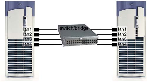
As you can see, we not only supply the MAC address of the other machine but we also specify the PPA of the interface on our machine over which the MAC frame will be sent. Where we have multiple interfaces, this is crucial; otherwise, we might not get a response because an interface is plugged into a different switch. In a High Availability scenario, we commonly have multiple interfaces plugged into the same switch, and in such a scenario, we need to ensure that all interfaces can communicate among each other, i.e., two interfaces per node (e.g., lan0 and lan1), with two nodes requires four linkloop commands: lan0 → lan0, lan0 → lan1, lan1 → lan0, and lan1 → lan1. If any of these linkloop commands fail, we need to investigate further; it may be that the switch is filtering certain MAC addresses on a port-by-port basis or the 802.1 Spanning Tree algorithm has been disabled for the switch. Other problems may include cable or interface card problems. Replacing a cable is relatively simple. Before you replace an interface card, you may wish to reset it via lanadmin. If the reset fails, there may be a problem with the card, the cable, or the hub/switch; whichever it is that needs further investigation.
root@hpeos003[] lanadmin


          LOCAL AREA NETWORK ONLINE ADMINISTRATION, Version 1.0
                       Mon, Sep 15,2003  14:33:07

               Copyright 1994 Hewlett Packard Company.
                       All rights are reserved.

Test Selection mode.

        lan      = LAN Interface Administration
        menu     = Display this menu
        quit     = Terminate the Administration
        terse    = Do not display command menu
        verbose  = Display command menu

Enter command: l

LAN Interface test mode. LAN Interface PPA Number = 0

        clear    = Clear statistics registers
        display  = Display LAN Interface status and statistics registers
        end      = End LAN Interface Administration, return to Test Selection
        menu     = Display this menu
        ppa      = PPA Number of the LAN Interface
        quit     = Terminate the Administration, return to shell
        reset    = Reset LAN Interface to execute its selftest
        specific = Go to Driver specific menu

Enter command: p
Enter PPA Number. Currently 0: 1

LAN Interface test mode. LAN Interface PPA Number = 1

        clear    = Clear statistics registers
        display  = Display LAN Interface status and statistics registers
        end      = End LAN Interface Administration, return to Test Selection
        menu     = Display this menu
        ppa      = PPA Number of the LAN Interface
        quit     = Terminate the Administration, return to shell
        reset    = Reset LAN Interface to execute its selftest
        specific = Go to Driver specific menu

Enter command: r
Resetting LAN Interface to run selftest.

LAN Interface test mode. LAN Interface PPA Number = 1

        clear    = Clear statistics registers
        display  = Display LAN Interface status and statistics registers
        end      = End LAN Interface Administration, return to Test Selection
        menu     = Display this menu
        ppa      = PPA Number of the LAN Interface
        quit     = Terminate the Administration, return to shell
        reset    = Reset LAN Interface to execute its selftest
        specific = Go to Driver specific menu

Enter command: d

                      LAN INTERFACE STATUS DISPLAY
                       Mon, Sep 15,2003  14:33:16

PPA Number                      = 1
Description                     = lan1 HP A5506B PCI 10/100Base-TX 4 Port [NO LINK,,AUTO,TT=1500]
Type (value)                    = ethernet-csmacd(6)
MTU Size                        = 1500
Speed                           = 10000000
Station Address                 = 0x306e467bf0
Administration Status (value)   = up(1)
Operation Status (value)        = down(2)
Last Change                     = 1756771
Inbound Octets                  = 432356
Inbound Unicast Packets         = 0
Inbound Non-Unicast Packets     = 1971
Inbound Discards                = 0
Inbound Errors                  = 0
Inbound Unknown Protocols       = 1971
Outbound Octets                 = 156
Outbound Unicast Packets        = 4
Outbound Non-Unicast Packets    = 0
Outbound Discards               = 0
Outbound Errors                 = 0
Outbound Queue Length           = 0
Specific                        = 655367

Press <Return> to continue

Ethernet-like Statistics Group

Index                           = 2
Alignment Errors                = 0
FCS Errors                      = 0
Single Collision Frames         = 0
Multiple Collision Frames       = 0
Deferred Transmissions          = 0
Late Collisions                 = 0
Excessive Collisions            = 0
Internal MAC Transmit Errors    = 0
Carrier Sense Errors            = 0
Frames Too Long                 = 0
Internal MAC Receive Errors     = 0

LAN Interface test mode. LAN Interface PPA Number = 1

        clear    = Clear statistics registers
        display  = Display LAN Interface status and statistics registers
        end      = End LAN Interface Administration, return to Test Selection
        menu     = Display this menu
        ppa      = PPA Number of the LAN Interface
        quit     = Terminate the Administration, return to shell
        reset    = Reset LAN Interface to execute its selftest
        specific = Go to Driver specific menu

Enter command: q
root@hpeos003[]
Remember that resetting a LAN interface will disrupt any connections currently established over that interface. From the above output, the Administration Status of UP simply means that the card is working. The Operation State of DOWN simply means that we have configured an IP address to that card; this used to be displayed in the output from lanscan (HP-UX 10.X) as a Hardware State and a Software State.
As I am sure we are all aware, a MAC (Media Access Control) address is sometimes referred to as our hardware address or station address. It is the 48-bit address where the first 24 bits are a vendor-assigned address (http://www.iana.org/assignments/ethernet-numbers) and the remaining 24 bits identify individual interfaces. All MAC addresses within a given network should be unique. When a node has an IP packet to send to a node on the same network, it needs to know the destination MAC address. It will look up the ARP (Address Resolution Protocol) cache to see whether it has a corresponding IP to MAC address translation. If not, it will send an ARP packet on the network with the destination IP address but with a destination MAC address of FF:FF:FF:FF:FF:FF. All nodes on the network will read this ARP packet. The node with the corresponding IP address will respond by sending back an ARP packet with its corresponding MAC address. In this way, one node will build up an ARP cache of the nodes with which it is commonly consulting. If after 7 minutes (by default) we haven't communicated with a particular node, the corresponding entry in the ARP cache will be flushed to minimize any kernel memory overhead due to structures that are not being used. If we do not have uniqueness of MAC addresses in our network, this algorithm will break down because more than two nodes could potentially respond to an ARP request. Some people think MAC addresses are unique worldwide; ideally, they would be. A 48-bit address gives us 281,474,976,710,656 potential interface cards in the world. It is hoped that this range of possible addresses would give us complete uniqueness. If every potential vendor number was used and vendors carefully used their allocated addresses (224 gives each vendor assigned address a possible 16,777,216 potential interface cards), we would never see duplicates. Unfortunately, duplicates do appear. If they are physically on separate networks, this may pose no problems. If they are on similar networks, this will cause problems.
I have worked with a number of customers who need to be able to change the MAC address for a LAN interface due to the way a particular application works. In one instance, the application was a telecoms application that used the MAC address of an interface to communicate with a telecoms switch. If the LAN interface failed and had to be changed, the application would have to be reconfigured for the new LAN interface. Changing the configuration of the application was a troublesome task, so it was desirable to change the MAC address of the new interface to be the same as the MAC address of the old interface. To change the MAC address, we have two solutions:
Replace the offending card to ensure that the MAC address is now unique; this is counter-productive where we want to maintain the old MAC address for licensing/application considerations.
Change the MAC address via
lanadmin.
The first solution is a little drastic, but for many corporations it is a reasonable request of a hardware vendor to supply components that are operational. I know of many sites that will return LAN cards to the vendor if a duplicate MAC address is discovered. The second solution seems more reasonable but is not entirely fool proof. Some licensing software will use the MAC address programmed into the LAN card, so changing the MAC address as described in solution 2 above is not actually changing the programmed MAC address on the LAN card. The lanadmin command is simply setting up a kernel structure that translates the old MAC address to a new MAC address. There is another problem with using solution 2 above; what if you choose a MAC address that conflicts with an existing or future valid MAC address? This has to be considered before proceeding. Should we choose solution 2, there are some considerations before undertaking what is in effect a relatively simple task:
Let's look a little closer at these steps:
Decide on the new MAC address.
We have mentioned the importance of having unique MAC addresses on a given network. If you do need to change the MAC address of a LAN card, try to discover all MAC addresses on your network to ensure that the one you choose is currently unique. A simple way of accomplishing this is to
pingthe broadcast address of your network and then look up the ARP cache. Most UNIX machines will respond to this, although some Windows-based machines probably will not. Here's an example:root@hpeos004[] netstat -in Name Mtu Network Address Ipkts Ierrs Opkts Oerrs Coll lan0 1500 192.168.0.0 192.168.0.204 8994 0 8929 0 626 lo0 4136 127.0.0.0 127.0.0.1 1118 0 1118 0 0 root@hpeos004[] ifconfig lan0 lan0: flags=843<UP,BROADCAST,RUNNING,MULTICAST> inet 192.168.0.204 netmask ffffff00 broadcast 192.168.0.255 root@hpeos004[] ping 192.168.0.255 PING 192.168.0.255: 64 byte packets 64 bytes from 192.168.0.204: icmp_seq=0. time=0. ms 64 bytes from 192.168.0.203: icmp_seq=0. time=0. ms 64 bytes from 192.168.0.201: icmp_seq=0. time=0. ms 64 bytes from 192.168.0.202: icmp_seq=0. time=0. ms 64 bytes from 192.168.0.100: icmp_seq=0. time=2. ms 64 bytes from 192.168.0.204: icmp_seq=1. time=0. ms 64 bytes from 192.168.0.203: icmp_seq=1. time=0. ms 64 bytes from 192.168.0.201: icmp_seq=1. time=0. ms 64 bytes from 192.168.0.202: icmp_seq=1. time=0. ms 64 bytes from 192.168.0.100: icmp_seq=1. time=1. ms 64 bytes from 192.168.0.204: icmp_seq=2. time=0. ms 64 bytes from 192.168.0.203: icmp_seq=2. time=0. ms 64 bytes from 192.168.0.201: icmp_seq=2. time=0. ms 64 bytes from 192.168.0.202: icmp_seq=2. time=0. ms 64 bytes from 192.168.0.100: icmp_seq=2. time=1. ms ^C ----192.168.0.255 PING Statistics---- 3 packets transmitted, 15 packets received, -400% packet loss round-trip (ms) min/avg/max = 0/0/2 root@hpeos004[] arp -a hpeos001 (192.168.0.201) at 8:0:9:ba:84:1b ether hpeos002 (192.168.0.202) at 8:0:9:c2:69:c6 ether ckpc2.mshome.net (192.168.0.1) at 0:8:74:e5:86:be ether hpeos003 (192.168.0.203) at 0:30:6e:5c:3f:f8 ether
Set up the corresponding startup configuration file to specify the new MAC address.
The LAN card you are using will determine the configuration file you need to update. Table 15-2 lists the types of cards you may have, the corresponding kernel driver, and the associated startup configuration file (check your system documentation if do not see your particular network card in this list):
Table 15-2. Startup Configuration Files for Various Network Cards
HP-UX 11i
PCI card (A, L, N, V-class, Superdome)
HSC card (D, K, T-class)
EISA card (D-class)
HP-PB card (K, T-class)
Core 10/100 card
Driver
btlan
lan2/lan3
lan2
lan3
Config. file
hpbtlanconf
hpetherconf
hpetherconf
hpetherconf
Startup script
hpbtlan
Hpether
hpether
hpether
Add-on 10/100 card
Driver
btlan
btlan
btlan0
btlan1
Config. file
hpbtlanconf
hpbtlanconf
hpeisabtconf
hpbasetconf
Startup script
hpbtlan
hpbtlan
hpeisabt
hpbaset
HP-UX 11i
A, L, N, V, Superdome and Workstations
rp74X0
rp84X0
Core 10/100/1000 card
Driver
Igelan
gelan
Config. file
hpigelanconf
hpgelanconf
Startup script
hpigelan
hpgelan
Add-on 10/100/1000 card
Driver
gelan
gelan
gelan
gelan
Config. file
hpgelanconf
hpgelanconf
hpgelanconf
hpgelanconf
Startup script
hpgelan
hpgelan
hpgelan
hpgelan
The individual configuration files may be slightly different in content, but the overall structure is somewhat similar. Here is an example of the configuration file
/etc/rc.config.d/hpbtlanconf:root@hpeos004[] more /etc/rc.config.d/hpbtlanconf ##################################################################### # @(#)B.11.11_LR hpbtlanconf $Revision: 1.1.119.1 $ $Date: 97/04/10 15:49:13 $ # hpbase100conf: contains configuration values for HP PCI/HSC 100BASE-T # interfaces # # HP_BTLAN_INTERFACE_NAME Name of interface (lan0, lan1...) # HP_BTLAN_STATION_ADDRESS Station address of interface # HP_BTLAN_SPEED Speed and duplex mode # Can be one of : 10HD, 10FD, 100HD, 100FD and # AUTO_ON. # # The interface name, major number, card instance and ppa may be # obtained from the lanscan(1m) command. # # The station address and duplex are set through the lanadmin(1m) command. # ##################################################################### HP_BTLAN_INTERFACE_NAME[0]= HP_BTLAN_STATION_ADDRESS[0]= HP_BTLAN_SPEED[0]= ########################################################################### # The HP_BTLAN_INIT_ARGS are reserved by HP. They are NOT user changable. ########################################################################### HP_BTLAN_INIT_ARGS="HP_BTLAN_STATION_ADDRESS HP_BTLAN_SPEED" # End of hpbtlanconf configuration file root@hpeos004[]For each interface I wish to change, I will copy and paste the three configuration lines, increasing the array subscript by one each time. The important lines for this configuration are:
HP_BTLAN_INTERFACE_NAME[0]="lan1"
HP_BTLAN_STATION_ADDRESS[0]="0x080009bbbbbb"
Here I am changing the MAC address of
lan1to0x080009bbbbbb. If I were to apply this configuration, I would lose all connections onlan1, so be very careful. I do not have an active connection on this interface, so I should be okay.Change the MAC address by rebooting or running the
lanadmincommand manually.
In my case, I will choose to run the lanadmin command manually. I will run it via the startup script /sbin/init.d/hpbtlan to ensure that my configuration file has been set up properly:
root@hpeos004[] lanscan
Hardware Station        Crd Hdw   Net-Interface  NM  MAC       HP-DLPI DLPI
Path     Address        In# State NamePPA        ID  Type      Support Mjr#
0/0/0/0  0x00306E5C4F4F 0   UP    lan0 snap0     1   ETHER     Yes     119
0/2/0/0/4/0 0x00306E46996C 1   UP    lan1 snap1     2   ETHER     Yes     119
0/2/0/0/5/0 0x00306E46996D 2   UP    lan2 snap2     3   ETHER     Yes     119
0/2/0/0/6/0 0x00306E46996E 3   UP    lan3 snap3     4   ETHER     Yes     119
0/2/0/0/7/0 0x00306E46996F 4   UP    lan4 snap4     5   ETHER     Yes     119
root@hpeos004[] cat /etc/rc.config.d/hpbtlanconf
#####################################################################
# @(#)B.11.11_LR hpbtlanconf $Revision: 1.1.119.1 $ $Date: 97/04/10 15:49:13 $
# hpbase100conf: contains configuration values for HP PCI/HSC 100BASE-T
# interfaces
#
# HP_BTLAN_INTERFACE_NAME   Name of interface (lan0, lan1...)
# HP_BTLAN_STATION_ADDRESS  Station address of interface
# HP_BTLAN_SPEED            Speed and duplex mode
#                           Can be one of : 10HD, 10FD, 100HD, 100FD and
#                           AUTO_ON.
#
# The interface name, major number, card instance and ppa may be
# obtained from the lanscan(1m) command.
#
# The station address and duplex are set through the lanadmin(1m) command.
#
#####################################################################

HP_BTLAN_INTERFACE_NAME[0]="lan1"
HP_BTLAN_STATION_ADDRESS[0]="0x080009bbbbbb"
HP_BTLAN_SPEED[0]=

###########################################################################
#  The HP_BTLAN_INIT_ARGS are reserved by HP. They are NOT user changable.
###########################################################################

HP_BTLAN_INIT_ARGS="HP_BTLAN_STATION_ADDRESS HP_BTLAN_SPEED"

# End of hpbtlanconf configuration file
root@hpeos004[] /sbin/init.d/hpbtlan start
root@hpeos004[] lanscan
Hardware Station        Crd Hdw   Net-Interface  NM  MAC       HP-DLPI DLPI
Path     Address        In# State NamePPA        ID  Type      Support Mjr#
0/0/0/0  0x00306E5C4F4F 0   UP    lan0 snap0     1   ETHER     Yes     119
0/2/0/0/4/0 0x080009BBBBBB 1   UP    lan1 snap1     2   ETHER     Yes     119
0/2/0/0/5/0 0x00306E46996D 2   UP    lan2 snap2     3   ETHER     Yes     119
0/2/0/0/6/0 0x00306E46996E 3   UP    lan3 snap3     4   ETHER     Yes     119
0/2/0/0/7/0 0x00306E46996F 4   UP    lan4 snap4     5   ETHER     Yes     119
root@hpeos004[]
The actual command used would be of the following form (the last command line argument is the PPA number of the interface):
root@hpeos004[] lanadmin -A 0x080009bbbbbb 1
Old Station Address                 = 0x00306e46996c
New Station Address                 = 0x080009bbbbbb
root@hpeos004[]
Before we look at applying an IP address to some of these interfaces, let's mention the speed of our interface and an interesting subject—auto-negotiation.
If we have a Fast Ethernet (10/100 Mbits per second) interface card, we have the option of specifying the speed and mode (full or half duplex) of the connection. The switch we are using will determine the speed and mode that is possible. If we refer to the example we used previously, the configuration file was /etc/rc.config.d/hpbtlanconf:
root@hpeos004[] more /etc/rc.config.d/hpbtlanconf
#####################################################################
# @(#)B.11.11_LR hpbtlanconf $Revision: 1.1.119.1 $ $Date: 97/04/10 15:49:13 $
# hpbase100conf: contains configuration values for HP PCI/HSC 100BASE-T
# interfaces
#
# HP_BTLAN_INTERFACE_NAME   Name of interface (lan0, lan1...)
# HP_BTLAN_STATION_ADDRESS  Station address of interface
# HP_BTLAN_SPEED            Speed and duplex mode
#                           Can be one of : 10HD, 10FD, 100HD, 100FD and
#                           AUTO_ON.
#
# The interface name, major number, card instance and ppa may be
# obtained from the lanscan(1m) command.
#
# The station address and duplex are set through the lanadmin(1m) command.
#
#####################################################################

HP_BTLAN_INTERFACE_NAME[0]="lan1"
HP_BTLAN_STATION_ADDRESS[0]="0x080009bbbbbb"
HP_BTLAN_SPEED[0]=

###########################################################################
#  The HP_BTLAN_INIT_ARGS are reserved by HP. They are NOT user changable.
###########################################################################

HP_BTLAN_INIT_ARGS="HP_BTLAN_STATION_ADDRESS HP_BTLAN_SPEED"

# End of hpbtlanconf configuration file
root@hpeos004[]
As we can see, the HP_BTLAN_SPEED configuration parameter has been left at the default value, which is AUTO_ON. This is the option to specify auto-negotiation. If we want to specify a particular speed and mode, we have two jobs to do:
Configure the speed and mode in the appropriate HP-UX configuration file.
Set the speed and mode on the individual switch port.
We can check the current speed and mode of an interface with the lanadmin command:
root@hpeos004[] lanadmin -s 1
Speed                           = 10000000
root@hpeos004[]
This is simply the speed. To view other driver settings, we use the –x option:
root@hpeos004[] lanadmin -x 1
Current Config                   = 10 Half-Duplex AUTONEG
root@hpeos004[]
From here, we can see that the speed and mode have auto-negotiated to 10 Mbits/second half duplex. This may be due to the fact that the switch port can only support this speed and mode. It may also be due to a disparity in the configuration of either the LAN interface or the switch port.
Auto-negotiation between Fast Ethernet devices is defined in the ANSI/IEEE 802.3u standard. It provides a mechanism known as Parallel Detection for multi-speed devices to configure appropriate settings. I won't bore you with the details. If you are interested, there is a good article on this that you can find on the Web (http://docs.hp.com/hpux/onlinedocs/netom/autonegotiation.pdf). I have also included it in Appendix D. The upshot is this: Either use a fixed, manual configuration, or use auto-negotiation at both ends of the link. When two multi-speed devices are using auto-negotiation, they can auto-negotiate speed, mode, and standard settings for the given connection. If one port is auto-negotiating while the other is using a fixed configuration, the mode setting will go undetected and could cause serious performance problems. If you want to get the most out of your LAN interface and switch port, you will have to perform some level of manual configuration. Let's assume that we have a LAN interface card and a switch port both capable of 100 MB/s full duplex. Table 15-3 describes the resulting speed and mode settings for various combinations of configuration settings.
Table 15-3. When Auto-Negotiation Works
Server LAN interface | Switch Port setting | Result |
|---|---|---|
AUTO | AUTO | 100FD |
10HD | 10HD | 10HD |
10FD | 10FD | 10FD |
100HD | 100HD | 100HD |
100FD | 100FD | 100FD |
AUTO | 10HD | 10HD |
AUTO | 10FD | 10HD[1] |
AUTO | 100HD | 100HD |
AUTO | 100FD | 100HD[1] |
[1] In this case, the LAN interface card does not receive FLPs (fast link pulses) from the switch because the switch port is set to a specific speed/duplex setting and is not auto-negotiating. Since the LAN interface card is auto-negotiating, it will parallel detect the 10/100Base-T signals from the switch and set the speed correctly. However, parallel detection cannot detect the duplex mode, so the duplex mode will default to half duplex. The resulting link configuration will be able to send and receive frames, but performance will be poor because the full duplex MAC disables the carrier sense and collision-detect circuitry. So when it has frames to transmit, it will transmit irrespective of what the half duplex MAC is doing. This will cause collisions with the full duplex MAC not backing off. At low traffic levels, the administrator may not detect any performance issues. At high traffic levels, the device configured for full duplex mode will be experiencing a high number of CRC and alignment errors because its collision detect circuitry has been disabled. This is commonly reported as a “bad cable” problem, which is somewhat confusing. The degradation in performance can be considerable, even to the point where you start to wonder why you invested in a Fast Ethernet card in the first place. | ||
By the time we got around to Gigabit Ethernet, the 802.3z standard that controls this link technology realized this problem and does not allow the link to come up when we have one side of the link auto-negotiating while the other is using a fixed configuration.
Remember: Either auto-negotiate or set a fixed manual configuration at both ends of the link.
These are the entries I would add to the startup configuration file:
HP_BTLAN_INTERFACE_NAME[0]="lan1"
HP_BTLAN_STATION_ADDRESS[0]="0x080009bbbbbb"
HP_BTLAN_SPEED[0]=100FD
Here are the associated commands to set these values (in this example, we have included changing the MAC address by specifying the HP_BTLAN_STATION_ADDRESS[0]="0x080009bbbbbb" parameter):
root@hpeos004[] lanadmin -A 0x080009bbbbbb 1
Old Station Address                 = 0x00306e46996c
New Station Address                 = 0x080009bbbbbb
root@hpeos004[] lanadmin -X 100FD 1

WARNING: an incorrect setting could cause serious network problems!

Driver is attempting to set the new speed
Reset will take approximately 11 seconds

root@hpeos004[]
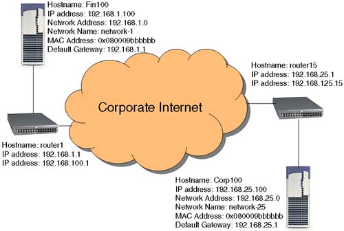
The most common version of IP addressing in use today is still IP version 4 (IPv4). This is the 32-bit address that identifies not only a host but also the network to which the host is connected. When we are communicating with another machine, it is said that the IP software has a basic decision to make: Is the destination host on a local network or a remote network? Figure 15-1 shows the fundamental question posed to the IP software regarding the location of another host.
At the heart of this concept are the notion of routing and the fact that an individual LAN interface can reside only in one logical network. If a server has several LAN interfaces (either physical or logical), each interface will have an individual IP address. It is possible to configure multiple physical interfaces with the same network address, but it is more common to configure each interface with an IP address that identifies that interface to be a member of a different network. The kernel will maintain a routing table of all the routes we have to all configured networks; by default, this routing table will simply document which interfaces are configured with IP addresses and which network addresses they relate to. In this way, a server with multiple LAN interfaces is acting as a router.
An IPv4 address is a 32-bit address that is most commonly represented in the dotted octet notation: dotted because we use dots to separate different parts of the address, and octet because the major components of the address are four 8-bit parts with each part having a maximum decimal value of 255. How we configure the first 5 bits of the address will determine which class of IP address we are using and by default how the IP address is divided into its two distinct identifiers: the network address (or net ID) and the host address (or host ID). The reason for setting up classes of IP address was to distinguish the size, complexity, and use of individual networks. Table 15-4 shows the five classes designed into the IPv4 address:
Class D (the first octet being 224 → 239 inclusive) addresses are only used by multicast applications, e.g., dynamic routing, and Class E addresses (the first octet being 240 → 255 inclusive) are not used. This leaves us with Class A to C addresses to use for individual LAN interfaces. I never found this description using bit-fields easy to understand or visualize. Table 15-5 shows how I interpret the IPv4 address classes:
The organization that assigns network addresses is known as the Internet Assigned Number Authority (IANA: http://www.iana.org); however, when an organization joins the Internet, it can obtain a network number from an organization known as the Network Information Center or InterNIC (http://www.internic.net). We can apply to InterNIC for a network address; although regional addressing authorities look after four major geographical locations (see http://www.iana.org/ipaddress/ip-addresses.htm for details). Once we have a network address, we can use the range of addresses within it to assign to individual hosts, or we can utilize a specific subnet mask to divide the host address into multiple network addresses. When determining our network address, the IP software will perform a logical AND operation with our IP address and our subnet mask to produce our network address. When communicating with another node, it will perform the same logical AND operation, and if the resulting network address is different, we must be communicating with a node on a different logical network behind a least one router, i.e., we consult our routing table to find the route to that network. Otherwise, both network addresses are the same, which means the node is connected to the same logical network and, hence, we consult our ARP cache to obtain the MAC address of that node.
As we should know, certain addresses are reserved; we mentioned Class D and Class E addresses previously. Certain other addresses are meant to signify specific entities: 1's represent “all”; in the context of a host ID, 1's would represent “all hosts”, commonly known as a broadcast address. All 0's on the other hand signify “this”; a host ID of all 0's is meant to signify “this host”; however, there is a long-standing error in Berkley UNIX (and in HP-UX) the implementation of which allows a host to use all 0's as a broadcast address. In my case, the last octet is my host ID, but if I use all 0's, I get a response from all HP machines on my network:
root@hpeos003[] ping 192.168.0.0
PING 192.168.0.0: 64 byte packets
64 bytes from 192.168.0.203: icmp_seq=0. time=0. ms
64 bytes from 192.168.0.204: icmp_seq=0. time=0. ms
64 bytes from 192.168.0.201: icmp_seq=0. time=0. ms
64 bytes from 192.168.0.202: icmp_seq=0. time=0. ms
64 bytes from 192.168.0.100: icmp_seq=0. time=2. ms
64 bytes from 192.168.0.203: icmp_seq=1. time=0. ms
64 bytes from 192.168.0.204: icmp_seq=1. time=0. ms
64 bytes from 192.168.0.201: icmp_seq=1. time=0. ms
64 bytes from 192.168.0.202: icmp_seq=1. time=1. ms
64 bytes from 192.168.0.100: icmp_seq=1. time=1. ms

----192.168.0.0 PING Statistics----
2 packets transmitted, 10 packets received, -400% packet loss
round-trip (ms)  min/avg/max = 0/0/2
root@hpeos003[]
In layman's terms, all 0's in a host ID will signify “this network”. When we obtain our network ID, it is common for us to use part of the host ID to form a network address; this is the idea of subnetting.
Let's start by looking at an example of HP's Class A address of 15. If HP network administrators had no other option, this would mean that HP had only one internal network that could accommodate 16,777,216 hosts. This is impractical, so we need to look to subnetting as a means of providing different network addresses and hence the ability to set up different networks. The traditional mechanism for doing this is to establish a subnet mask that will steal a number of bits from the host ID to form the overall network ID. Let's take a Class C network address as an example: 192.168.0.1. By default, our subnet mask is 255.255.255.0. We need to modify the default subnet mask so that, when we perform the logical AND operation, with the IP address, it will produce a different network ID. The big question we need to ask, regardless of whether we have a Class A, B, or C address is, “How many networks do I need?” In an organization that has a Class A (or possibly even a Class B) address, you may ask, “How many geographic regions do I have?” because each region could further refine the subnet mask for its own individual requirements. In our example, we have five networks to set up: IT, Research, Marketing, Finance, and Sales. We need to determine how many bits of the host ID to steal in order to achieve the necessary number of networks. If we take a power of two, which achieves at least the number of networks we require: 22 = 4, it's not enough; 23 = 8, that's enough. Be careful with this because if we needed only four networks, we may have chosen to steal only two bits of the host ID. The problem here is that when we are subnetting we need to remember the conventions of “all 1's” representing “all hosts” in the network and “all 0's” representing the entire network. Although these conventions still apply, we will see that we have various network and broadcast addresses for a single Class C IP address range. Although the IP software will work with the “all 0's” and “all 1's” scenarios, it's advisable to avoid the “all 0's” and “all 1's” in the last octet because such a situation is normally reserved for a non-subnetted network. The formula we should use is this:
2n >= number of networks required + 2
n = number of bits to steal from the host ID
In our example, we need the following:
2n >= 5 + 2
n = 3
In our case, we will steal the top 3 bits of the host ID. These top 3 bits represent 128 + 64 + 32 = 224 from the binary to decimal conversion. This means that our new subnet mask will be 255.255.255.224. This has an immediate impact on which IP addresses I use for particular hosts. Previously, any IP address in my Class C network would provide a network address of 192.168.0.0. Now, different IP addresses will provide different network addresses (we will represent the last octet of the IP address and Subnet Mask in binary to make the logical AND operation easier to follow). Table 15-6 shows the effect the choice of a subnet mask has on the resulting network address.
There are other consequences of subnetting; as you can see, we can no longer use particular IP addresses (e.g., 192.168.0.32) because they represent specific entities within our network (a network address in this instance). The outcome of this should be a planning document (see Table 15-7) that details the different network addresses now in use, the ranges of IP addresses within each network that are allowed, and the resulting broadcast address expected, i.e., the broadcast address is the IP address with all 1's in the host ID component.
Table 15-7. Planning Document for a Subnetted Network
High Order 3-bit Sequence of 4th Octet | Network Address | Range of IP Addresses | Broadcast Address |
|---|---|---|---|
000 | Not allowed; all 0's should represent the entire network | ||
001 | 192.168.0.32 | 192.168.0.33→62 | 192.168.0.63 |
010 | 192.168.0.64 | 192.168.0.65→94 | 192.168.0.95 |
011 | 192.168.0.96 | 192.168.0.97→126 | 192.168.0.127 |
100 | 192.168.0.128 | 192.168.0.129→158 | 192.168.0.159 |
101 | 192.168.0.160 | 192.168.0.161→190 | 192.168.0.191 |
110 | 192.168.0.192 | 192.168.0.193→222 | 192.168.0.223 |
111 | Not allowed; all 1's should represent a broadcast address | ||
You should notice a few things right away:
We have a significantly reduced the number of IP addresses available to use.
Changing this configuration will affect every machine in our network.
Every machine in our network uses the subnet mask of 255.255.255.224.
Every machine that is now in a different network will need to know the IP address of its local router in order to communicate with other machines in the organization.
All the subnets have the ability to accommodate the same number of hosts: in this case, 30.
An alternative to using the traditional mechanism for establishing a subnet mask is to think about the problem in a slightly different way. The question we asked previously was, “How many networks do I need?” This did not take into account the requirement for having more or less than 30 nodes per subnet. If we were to adopt a different strategy, the question we might ask ourselves is, “How many nodes do I need per subnet?” This leads to different subnets having different subnet masks, or variable length subnet masks. If I wanted a subnet to support 50 clients, I would allocate a subnet mask of 192: 192 steals 2 bits from the host ID, leaving 26 = 64 bits to specify individual hosts. This would allow for my 50 clients as well as for expansion up to 62 clients (one address for the network address and one for the broadcast address). If I wanted to permit only six hosts, I would apply a subnet mask of 248, and so on. Another important part of variable length subnet masks is to ensure that each subnet has a unique subnet address. We do this by carefully selecting the range of IP addresses that each subnet will use. Table 15-8 shows the impact of using a differing size of subnet mask on our Class C address 192.168.0:
With variable length subnet masks, we are utilizing our Class C address more efficiently because it is based on current and projected usage of individual subnets.
We can now use the relevant ranges of IP addresses for our individual networks. In our case, we will have a range of IP addresses not used because we only have five networks currently. Once we have designed and planned our IP configuration, we can proceed with the next part of our network design: routing table entries.
Routing is important in order for our packets to reach and return from their destination. If we do not set it up correctly, we can run the risk of building inefficiencies into our network. Look at the example in Figure 15-2.
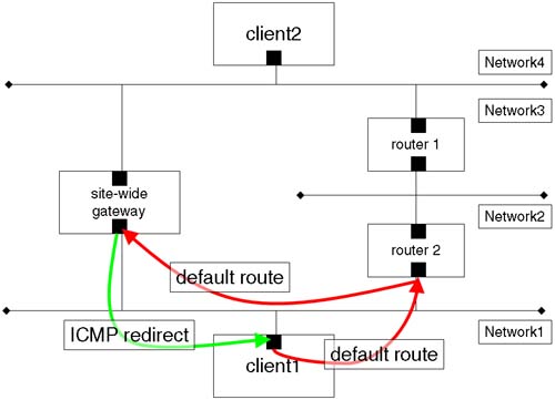
The routing protocols themselves are relatively efficient. The client (client1) has a default route to router2. In turn, router2 has various static routes entered into its routing table, possibly including a route to Network3 via router1. router2 also has a default route via the site-wide gateway, which has a direct connection between Network1 and Network4. The routing protocols allow for the site-wide gateway to send an ICMP redirect message to client1 to add a new route to its routing table to Network4 via the site-wide gateway. Let's get one thing straight here. The ICMP redirect sent by the site-wide gateway updates the routing table on client1; this is known as a dynamic route, and it is signified by a D flag in the output from netstat –r. Frequently, when we are talking about dynamic routing, more often than not we will be referring to the routing daemon gated and not to dynamic updates via ICMP redirect. In the example in Figure 15-2, we are talking about having static routes configured into our routing table. In Chapter 16, we look at configuring the routing daemon gated to dynamically change entries in our routing table.
Let's look at a simple example where we have static routes configured into our routing table and a static route fails. What happens when a static route fails? In our simple example, we will have a network configured as depicted in Figure 15-3.
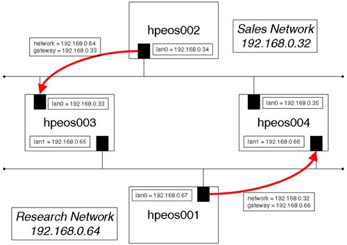
We can configure individual routes to individual networks as well as a default route that will be our exit point from our network, to all other networks not previously defined. In the example in Figure 15-3, we could configure the gateways listed as the default route for the respective nodes or list individual routes; however, with static routes this has limitations, as we see. The nodes hpeos003 and hpeos004 in Figure15-3 are said to be multi-homed hosts because they have at least two network interfaces that are configured on two separate subnets. These nodes will be acting as our routers. When routers are interconnected in a large network, they can also have static routes defined. In a complex network, this can become cumbersome to maintain and manage. Consequently, we commonly use the routing daemon gated in such a situation. We discuss gated and dynamic routing in the next chapter.
It is a good idea to have some form of plan in your new network design as in Figure 15-3. If we forget to perform one step, e.g., configure the static route for node hpeos002, both nodes will be affected. Packets won't be able to find their way back from the distant machine because a routing table entry will be missing.
Before we proceed with this global configuration change on all affected machines in the network, you should also remember that such a change would probably require a re-cabling of major parts of your network infrastructure.
With our IP address, subnet mask, and static routes in place, we can now configure /etc/rc.config.d/netconf to apply this new configuration.
At the heart of our IP configuration is the file /etc/rc.config.d/netconf. This is where we configure our IP addresses, subnet masks, and static routes. We can also enable other routing daemons, the main one being gated, which is responsible for dynamic routing. We will configure dynamic routing in the next chapter.
Here are the entries I added to /etc/rc.config.d/netconf, as well as the associated commands for the nodes in our example outlined in Figure 15-2:
Node =
hpeos001root@hpeos001[] vi /etc/rc.config.d/netconf ... INTERFACE_NAME[0]="lan0" IP_ADDRESS[0]="192.168.0.67" SUBNET_MASK[0]="255.255.255.224" BROADCAST_ADDRESS[0]="" INTERFACE_STATE[0]="" DHCP_ENABLE[0]=0 ... ROUTE_DESTINATION[0]="net 192.168.0.32" ROUTE_MASK[0]="255.255.255.224" ROUTE_GATEWAY[0]="192.168.0.66" ROUTE_COUNT[0]="1" ROUTE_ARGS[0]="" /sbin/ifconfig lan0 192.168.0.67 netmask 255.255.255.224 /sbin/route add net 192.168.0.32 mask 255.255.255.224 192.168.0.66 1
Node =
hpeos002root@hpeos002[] vi /etc/rc.config.d/netconf ... INTERFACE_NAME[0]="lan0" IP_ADDRESS[0]="192.168.0.34" SUBNET_MASK[0]="255.255.255.224" BROADCAST_ADDRESS[0]="" INTERFACE_STATE[0]="" DHCP_ENABLE[0]=0 ... ROUTE_DESTINATION[0]="net 192.168.0.64" ROUTE_MASK[0]="255.255.255.224" ROUTE_GATEWAY[0]="192.168.0.33" ROUTE_COUNT[0]="1" ROUTE_ARGS[0]="" /sbin/ifconfig lan0 192.168.0.34 netmask 255.255.255.224 /sbin/route add net 192.168.0.64 mask 255.255.255.224 192.168.0.33 1
Node =
hpeos003root@hpeos003[] vi /etc/rc.config.d/netconf ... INTERFACE_NAME[0]="lan0" IP_ADDRESS[0]="192.168.0.33" SUBNET_MASK[0]="255.255.255.224" BROADCAST_ADDRESS[0]="" INTERFACE_STATE[0]="" DHCP_ENABLE[0]=0 INTERFACE_NAME[1]="lan1" IP_ADDRESS[1]="192.168.0.65" SUBNET_MASK[1]="255.255.255.224" BROADCAST_ADDRESS[1]="" INTERFACE_STATE[1]="" DHCP_ENABLE[1]=0 /sbin/ifconfig lan0 192.168.0.33 netmask 255.255.255.224 /sbin/ifconfig lan1 192.168.0.65 netmask 255.255.255.224
Node =
hpeos004root@hpeos004[] vi /etc/rc.config.d/netconf ... INTERFACE_NAME[0]="lan0" IP_ADDRESS[0]="192.168.0.35" SUBNET_MASK[0]="255.255.255.224" BROADCAST_ADDRESS[0]="" INTERFACE_STATE[0]="" DHCP_ENABLE[1]=0 INTERFACE_NAME[1]="lan1" IP_ADDRESS[1]="192.168.0.66" SUBNET_MASK[1]="255.255.255.224" BROADCAST_ADDRESS[1]="" INTERFACE_STATE[1]="" DHCP_ENABLE[1]=0 /sbin/ifconfig lan0 192.168.0.35 netmask 255.255.255.224 /sbin/ifconfig lan1 192.168.0.66 netmask 255.255.255.224
NOTE: Remember to change the IP address/hostname pairing in your host's lookup database as well, e.g., /etc/hosts.
The other thing to point out here is that I have specified the subnet mask in my netconf file. Be sure to update the netconf file on all affected nodes in the network. If you forget to update a particular node, it will have a network address fundamentally different from all other nodes and will not be able to communicate with them without further intervention.
It is recommended that you reboot your system to ensure that all networking software is started up with the correct settings and in the correct order. I agree with the last part of that statement, but a reboot can take some time on larger servers; I would drop down to run-level 1 and then go back to my default run-level (run-level = 3 normally). If all goes well, I should be able to ping all hosts from all locations. If not, I need to spend time ensuring that all relevant configuration changes have taken place.
root@hpeos001[] # netstat -in
Name          Mtu Network            Address                 Ipkts      Opkts
lan0         1500 192.168.0.64       192.168.0.67             1482       1441
lo0          4136 127.0.0.0          127.0.0.1                1306       1306
root@hpeos001[] # netstat -rn
Routing tables
Destination           Gateway            Flags   Refs Interface  Pmtu
127.0.0.1             127.0.0.1          UH        0  lo0        4136
192.168.0.67          192.168.0.67       UH        0  lan0       4136
192.168.0.64          192.168.0.67       U         2  lan0       1500
192.168.0.32          192.168.0.66       UG        0  lan0          0
127.0.0.0             127.0.0.1          U         0  lo0           0
root@hpeos001[] # ping hpeos002 64 3
PING hpeos002: 64 byte packets
64 bytes from 192.168.0.34: icmp_seq=0. time=1. ms
64 bytes from 192.168.0.34: icmp_seq=1. time=1. ms
64 bytes from 192.168.0.34: icmp_seq=2. time=1. ms

----hpeos002 PING Statistics----
3 packets transmitted, 3 packets received, 0% packet loss
round-trip (ms)  min/avg/max = 1/1/1
root@hpeos001[] #
The problem with static routes is that they are exactly that: static. If we refer back to Figure 15-2, we notice that we actually have two routes between both networks. Let's add both of them into the routing table on node hpeos001:
root@hpeos001[] # route add net 192.168.0.32 192.168.0.65 1
add net 192.168.0.32: gateway 192.168.0.65
root@hpeos001[] # netstat -rn
Routing tables
Destination           Gateway            Flags   Refs Interface  Pmtu
127.0.0.1             127.0.0.1          UH        0  lo0        4136
192.168.0.67          192.168.0.67       UH        0  lan0       4136
192.168.0.64          192.168.0.67       U         2  lan0       1500
192.168.0.32          192.168.0.65       UG        0  lan0          0
192.168.0.32          192.168.0.66       UG        0  lan0          0
127.0.0.0             127.0.0.1          U         0  lo0           0
root@hpeos001[] #
And on node hpeos002:
root@hpeos002[] # route add net 192.168.0.64 192.168.0.35 1
add net 192.168.0.64: gateway 192.168.0.35
root@hpeos002[] # netstat -rn
Routing tables
Destination           Gateway            Flags   Refs Interface  Pmtu
127.0.0.1             127.0.0.1          UH        0  lo0        4136
192.168.0.34          192.168.0.34       UH        0  lan0       4136
192.168.0.32          192.168.0.34       U         2  lan0       1500
192.168.0.64          192.168.0.35       UG        0  lan0          0
192.168.0.64          192.168.0.33       UG        0  lan0          0
root@hpeos002[] #
Two things to notice:
The newly added route is the first in the list of gateway (UG) routes.
I did not use the
maskoption to theroutecommand, because this is not necessary when the destination network is using the same netmask as I am.
If we now access one node from the other, we will use the first route that allows us to get to our distant network:
root@hpeos001[] # traceroute hpeos002
traceroute to hpeos002 (192.168.0.34), 30 hops max, 40 byte packets
 1  hpeos003 (192.168.0.65)  1.027 ms  0.510 ms  0.514 ms
 2  hpeos002 (192.168.0.34)  1.077 ms  0.828 ms  0.775 ms
root@hpeos001[] #
As we can see, we are utilizing the route through node hpeos003 (192.168.0.65) because it is the first route in our routing table that allows us to access network 192.168.0.32. Let's now disable that route by simply removing that cable between hpeos003 and the hub/switch. Just to show you that all I have done is to remove the cable from node hpeos003, here's the output from netstat –in:
root@hpeos003[] netstat -in
Name      Mtu  Network         Address         Ipkts   Ierrs Opkts   Oerrs Coll
lan1*     1500 192.168.0.64    192.168.0.65    1060    0     1091    0     0
lan0      1500 192.168.0.32    192.168.0.33    1316    0     1051    0     4
lo0       4136 127.0.0.0       127.0.0.1       1220    0     1220    0     0
root@hpeos003[]
As you can see, the asterisks (*) signify that there is a problem with the link on lan1. Now, if we are to try a traceroute again, we should find that it would not use the second route even though it is alive and well.
root@hpeos001[] # traceroute hpeos002
traceroute to hpeos002 (192.168.0.34), 30 hops max, 40 byte packets
 1  * * *
 2  * * *
 3  * * *
 4  * * *
 5  * * *
 6  * * *
 7  * * *
 8  * * *
 9  * * *
10  * * *
11  * * *
12  * * *
13  * * *
14  * * *
15  * * *
16  * * *
17  * * *
18  * * *
19  * * *
20  * * *
21  * * *
22  * * *
23  * * *
24  * * *
25  * * *
26  * * *
27  * * *
28  * * *
29  * * *
30  * * *
**** max ttl expired before reaching hpeos002 (192.168.0.34)
root@hpeos001[] #
Simply replacing the cable resolved this problem. Remember, a static route is STATIC. The problem stems from the fact that these routes are seen as just that: routes. If they were seen as gateways, then the situation would be different. A command that we will look at in more detail later is ndd. Using the ndd command, we can extract information about network related kernel parameters. In this case, I am extracting the routing table. I have underlined the lines I am interested in:
root@hpeos002[] # ndd -get /dev/ip ip_ire_status
IRE      rfq     stq      addr           mask    src             gateway         mxfrg rtt   ref type               flag
02740ec8 026dfc80 00000000 000.000.000.000 ffffffff 192.168.000.034 000.000.000.000 04136 00000 000 IRE_BROADCAST
0273e288 026dfc80 026dfd44 000.000.000.000 ffffffff 192.168.000.034 000.000.000.000 01500 00000 006 IRE_BROADCAST
026dad08 00000000 00000000 127.000.000.001 ffffffff 127.000.000.001 000.000.000.000 04136 01430 000 IRE_LOOPBACK
02740448 026dfc80 00000000 192.168.000.255 ffffffff 192.168.000.034 000.000.000.000 04136 00000 000 IRE_BROADCAST
0273ed08 026dfc80 026dfd44 192.168.000.255 ffffffff 192.168.000.034 000.000.000.000 01500 00000 006 IRE_BROADCAST
027400c8 026dfc80 00000000 192.168.000.032 ffffffff 192.168.000.034 000.000.000.000 04136 00000 000 IRE_BROADCAST
0273f0c8 026dfc80 026dfd44 192.168.000.032 ffffffff 192.168.000.034 000.000.000.000 01500 00000 006 IRE_BROADCAST
02c8f448 026dfc80 026dfd44 192.168.000.033 ffffffff 192.168.000.034 000.000.000.000 01500 00000 001 IRE_ROUTE
0273bec8 026dfc80 00000000 192.168.000.034 ffffffff 192.168.000.034 000.000.000.000 04136 01034 000 IRE_LOCAL
02d88d08 026dfc80 026dfd44 192.168.000.035 ffffffff 192.168.000.034 000.000.000.000 01500 00000 002 IRE_ROUTE
0273fd08 026dfc80 00000000 192.168.000.063 ffffffff 192.168.000.034 000.000.000.000 04136 00000 000 IRE_BROADCAST
0273f448 026dfc80 026dfd44 192.168.000.063 ffffffff 192.168.000.034 000.000.000.000 01500 00000 006 IRE_BROADCAST
027407c8 026dfc80 00000000 192.168.000.000 ffffffff 192.168.000.034 000.000.000.000 04136 00000 000 IRE_BROADCAST
0273e988 026dfc80 026dfd44 192.168.000.000 ffffffff 192.168.000.034 000.000.000.000 01500 00000 006 IRE_BROADCAST
02740b48 026dfc80 00000000 255.255.255.255 ffffffff 192.168.000.034 000.000.000.000 04136 00000 000 IRE_BROADCAST
0273e608 026dfc80 026dfd44 255.255.255.255 ffffffff 192.168.000.034 000.000.000.000 01500 00000 006 IRE_BROADCAST
02741288 00000000 026dfc80 192.168.000.032 ffffffe0 192.168.000.034 000.000.000.000 01500 00000 002 IRE_RESOLVER
02d5a7c8 00000000 00000000 192.168.000.064 ffffffe0 192.168.000.034 192.168.000.035 00000 00000 000 IRE_NET
0273e0c8 00000000 00000000 192.168.000.064 ffffffe0 192.168.000.034
192.168.000.033 00000 00000 000 IRE_NET
019b4ec8 00000000 00000000 127.000.000.000 ff000000 127.000.000.001 127.000.000.001 00000 00000 000 IRE_NET
root@hpeos002[] #
These are the entries resulting from my route command. If they were marked as gateways, they would be probed every 3 minutes (by default), and if we don't get a response from a gateway, then it is marked as dead. We can see this by using the ndd command again:
root@hpeos002[] # ndd -get /dev/ip ip_ire_gw_probe
1
root@hpeos002[] #
This parameter means that we will probe gateways:
root@hpeos002[] # ndd -get /dev/ip ip_ire_gw_probe_interval
180000
root@hpeos002[] #
This parameter defines the time interval in milliseconds (3 minutes, in this case) when we probe gateways. The kernel will flush routing table entries of gateways every 20 minutes:
root@hpeos002[] # ndd -get /dev/ip ip_ire_flush_interval
1200000
root@hpeos002[] #
As expected, the routing daemon gated will update the routing table periodically. The kernel will still probe dead gateways in case they come back online. Gateways are managed by the routing daemon: gated. Manipulating the use of static routes will require you to get involved with the route command. This is the main reason that static routes are not so favored. Think about it this way. In this example, if the cable I was using had an intermittent problem, some connections would not be possible while the cable was faulting. Other connections would be okay when the cable was working normally. If we were to persist in using static routes, an administrator would have to manually maintain the relevant routing tables using the route command whenever a problem occurred. With the routing daemon gated, there is a good chance we would avoid any perceived disruption in service with the gated daemon dynamically updating routing tables automatically. As I mentioned previously, we discuss the routing daemon gated in the next chapter. Before moving on to RARP and DHCP, let me say a quick word on Proxy ARP.
The terms Proxy ARP, promiscuous ARP, and the “ARP hack” all relate to the same thing. This software setting is supported by some routers. The idea is to make setting up static routes as simple as possible. A very simple example is shown in Figure 15-4.
The important thing to not is the use of the route command; the nodes hpeos001 and hpeos003 appear to be our own default gateway. This means that when node hpeos002 wants to communicate with node hpeos001, it will simply send the packet on its local network; a hop count of 0 means that you are your own router to that particular network. When the initial ARP broadcast request packet is sent on the local network, routerX will realize that the particular IP address in question doesn't actually reside on the local network but resides elsewhere. The router running the proxy ARP software will respond to the broadcast ARP request by supplying its own MAC address back to node hpeos002. Subsequent communication will require routerX to receive the packets from hpeos002 destined for hpeos001, look up a special routing table that tells which physical network hpeos001 is actually located on, and forward the packets to node hpeos001. Packets returning from hpeos001 follow a similar route with routerX hiding the physical location of nodes from each other. When we think about the ARP cache on node hpeos002, there will be two IP address (IP addresses for routerX and hpeos001) mapping onto a single MAC address. To a security administrator, this is very suspect. This looks like one machine is spoofing another, i.e., pretending to be another machine by mapping someone else's IP address to your MAC address. This is not a violation of the ARP protocol, but simply an exploitation of an assumption made by the ARP protocol; all responses are legitimate. Proxy ARP may seem like a useful solution, but it does not scale well because the tables of nodes and addresses maintained on routerX commonly have to be maintained manually and are, therefore, prone to errors and take time and energy to maintain. I don't have a router that supports proxy ARP to show you in operation. In my experience, it is not used extensively due to the perceived security problems; lots of network monitoring software will alert administrators if they see two disparate IP addresses mapping to the same MAC address (although this is possible with IP multiplexing and is a required feature for package IP addresses in Serviceguard).
We have looked at applying an IP address to a node manually. Let us now look at setting up RARP and DHCP to allow nodes to acquire an IP address dynamically.
The problem with manually configuring IP addresses, subnet masks, and routing information is that lots of similar information is being applied in some cases to lots of individual machines. If these machines are purely clients of network services, then why should they worry about what their IP addresses are? The answer is they probably don't care about their IP addresses. This is where RARP and DHCP come in.
The first utility we look at to provide an IP address dynamically is RARP. This protocol has two components: a client (the rarpc command) and a server (the rarpd daemon). Let's discuss the limitation of RARP before we look at an example.
RARP was designed with one major client in mind: diskless workstations. When a diskless workstation boots up, it will broadcast on its network the only piece of network related information it knows: its MAC address. We hope that a RARP server will be listening for such a broadcast and will respond by furnishing (via tftp) the diskless client with an IP address and subsequently a mini NFS-enabled kernel to boot from. The rest of the boot-up procedure is (almost) the same as any other workstation. The thing to note here is that the only IP configuration parameter supplied by RARP is the IP address of the client. All other IP parameters need to be supplied in the relevant startup configuration files.
Another limitation of RARP is that it is only supported over Ethernet, 100VG, and FDDI interfaces.
To supply IP addresses to RARP clients, we need a RARP server. This is a machine on the same network (broadcasts do not normally cross a router) that has been configured as a RARP server. There are two components to being a RARP server:
Run the
rarpddaemon.NOTE: There is a bug in my (and probably your)
netconffile. The RARPD configuration parameter should read RARPD=1. If not, the startup script/sbin/init.d/rarpdwill not start the daemon. The configuration file below has the wrong parameter name in the comment. I have amended the actual parameter to be correct. Ensure that you have the most recent patches for RARP to avoid this.root@hpeos003[] vi /etc/rc.config.d/netconf ... # # Reverse ARP daemon configuration. See rarpd(1m) # # RARP: Set to 1 to start rarpd daemon # RARPD=1 root@hpeos003[] /sbin/init.d/rarpd start rarpd root@hpeos003[] ps -ef | grep rarp root 3413 1 0 17:46:02 ? 0:00 /usr/sbin/rarpd root@hpeos003[]
Have appropriate entries in the
/etc/rarpd.conffile.This file comes with some examples in it. You will need the MAC address of all your RARP clients and an associated IP address. I have updated this file with the MAC address for node
hpeos001; I have used a different IP address for demonstration purposes.root@hpeos003[] vi /etc/rarpd.conf ... 08:00:09:BA:84:1B 192.168.0.75
We are now ready to configure a machine to be a RARP client. Here are the configuration changes I made to node hpeos001 in order for it to set RARP to obtain its IP address:
root@hpeos001[] # vi /etc/rc.config.d/netconf
...
INTERFACE_NAME[0]="lan0"
IP_ADDRESS[0]=RARP
SUBNET_MASK[0]="255.255.255.224"
BROADCAST_ADDRESS[0]=""
INTERFACE_STATE[0]=""
DHCP_ENABLE[0]=0
This will result in the rarpc lan0 command being run at boot time. Here's an example of running the startup script manually:
root@hpeos001[] # netstat -in
Name     Mtu Network            Address                 Ipkts      Opkts
lan0    1500 192.168.0.64       192.168.0.67             3480       3043
lo0     4136 127.0.0.0          127.0.0.1                1306       1306
root@hpeos001[] #
root@hpeos001[] # /sbin/init.d/net start
root@hpeos001[] # netstat -in
Name     Mtu Network            Address                 Ipkts      Opkts
lan0    1500 192.168.0.64       192.168.0.75             3577       3108
lo0     4136 127.0.0.0          127.0.0.1                1306       1306
root@hpeos001[] #
With its limitations in regard of the number of different configuration parameters that you can initialize, RARP will probably remain in the realms of diskless workstations. To supply an IP configuration to a machine dynamically, the most popular tool is DHCP.
DHCP allows us to supply a plethora of configuration options to a client machine. These range from an IP address and subnet mask to default gateway, DNS servers, and even NTP timeservers. Every set of configuration parameters given out by the DHCP server has a lease expiry time. Before this time, the DHCP client can request an extension to the lease, which is normally granted by the DHCP server. In this way, a client may actually maintain the same IP configuration over a period of time. This is purely a consequence of the way leases work. Do not expect an individual client to maintain any IP-related parameters. Remember, DHCP clients are purely clients of network services. DHCP clients can be any network devices ranging from network printers, X-Terminals, diskless workstations, or Windows-based PCs to machines running HP-UX.
The client portion of the configuration is relatively simple; for each interface listed in /etc/rc.config.d/netconf, we have a DHCP_ENABLE parameter that when set to 1 will send a bootp broadcast request containing its MAC address on the local network. A DHCP server will respond and download the entire IP configuration to the client. I will configure node hpeos001 as a DHCP client:
root@hpeos001[] # vi /etc/rc.config.d/netconf
...
HOSTNAME=""
OPERATING_SYSTEM=HP-UX
LOOPBACK_ADDRESS=127.0.0.1
...
INTERFACE_NAME[0]="lan0"
IP_ADDRESS[0]=""
SUBNET_MASK[0]=""
BROADCAST_ADDRESS[0]=""
INTERFACE_STATE[0]=""
DHCP_ENABLE[0]=1
...
ROUTE_DESTINATION[0]=""
ROUTE_MASK[0]=""
ROUTE_GATEWAY[0]=""
ROUTE_COUNT[0]=""
ROUTE_ARGS[0]=""
As we can see, we are going to obtain our entire IP configuration from our DHCP server. In fact, when the configuration is downloaded, it will be stored in a file /etc/dhcpclient.data. After every reboot, we will request from the DHCP server an extension on the lease. Let's look at setting up the DHCP server.
A DHCP server needs to be accessible to all clients in your network. Let's reconsider our small network from Figure 15-2. Using node hpeos002 as a DHCP server has limitations. If node hpeos001 makes a DHCP request, the request may not pass through our routers. Some routers are DHCP-aware, but others are not. Where a router is not DHCP-aware, we will need to utilize a node on a local network to relay the DHCP request to its eventual destination. We look at this later. It is enough to say that using a well-connected (multi-homed) server as a DHCP server is desirable.
DHCP is a superset of the older bootp protocol. As such, it uses the bootpd daemon to listen for DHCP as well as bootp requests over its networks. We need to ensure that the bootps service is active in our /etc/inetd.conf file. If not, uncomment it and remember to run inetd –c to send an HUP signal to inetd to ensure that it rereads its configuration file. Here's the default entry from /etc/inetd.conf on node hpeos004:
root@hpeos004[] grep bootpd /etc/inetd.conf
bootps      dgram  udp wait   root /usr/lbin/bootpd   bootpd
root@hpeos004[]
The default configuration files used by a DHCP server are /etc/bootptab and /etc/dhcptab. There are three types of clients to which a DHCP server can respond:
An individual node
A pool group
A device group
You can either use SAM to configure these files or use an editor to modify the configuration files directly. There are lots of options to the IP configuration, so be sure that you know which options to use for a particular node.
Individual nodes have their IP configuration specified in /etc/bootptab. After checking /etc/dhcpdeny, which would refuse access based on MAC address, this is the next configuration file the bootpd daemon examines to check that we don't have a specific entry for a specific node. Here I have created an entry in /etc/bootptab for a machine with MAC address 0x080009ba841b (node hpeos001 actually):
root@hpeos004[] cat /etc/bootptab
...
client1:
        ht=ethernet:
        ha=080009ba841b:
        hn:
        gw=192.168.0.35:
        sr=192.168.0.32 192.168.0.33 :
        dn=maabof.com:
        ds=192.168.0.34:
        nt=192.168.0.34
I have chosen the following options:
client1:This is an identifier for an individual entry. It can be used as the hostname for an individual client.ht=Hardware type of Ethernet. Note that FDDI is not supported.ha=Hardware address of the client.hn:A Boolean expression that means that the hostname passed back to the client is the identifier tag at the beginning of this entry.gw=This is the IP address of the default gateway.sr=These are individual static routes.dn=The domain name to be used for DNS resolution.ds=The IP address of DNS server(s).nt=The IP address of NTP time server(s).
As you can see, even with these few options, there is much to consider. The order of options within individual entries is not important. The convention to have each configuration option on an individual line makes for easy reading and it is easier to identify syntax errors. I won't list all the available options here. The best place to find them is either in the /etc/bootptab itself where a list is provided in the comments at the beginning of the file or in man bootpd where a good explanation and useful examples of all the options are listed. I can continue with individual entries if I wish. This can be tedious, so we will look at setting up a pool group.
A pool group is a group of IP addresses that can be assigned to any client on a given subnet. Because we are using a server that has multiple network connections, we can define multiple pool groups for different subnets. Again, we can edit the configuration file /etc/dhcptab directly or use SAM. Initially, most administrators will use SAM because the number of options is quite bewildering. I will not list all of them here. The manual page for bootpd is a good place to start. It is important that you create a pool group for all the subnets you are servicing. When a DHCPDISCOVER request comes in from a client, it will be on a particular subnet; we need to have a pool group with a definition for such a subnet. Here is a basic entry for clients on our 192.168.0.64 network:
root@hpeos004[] more /etc/dhcptab
dhcp_pool_group:
        pool-name=64Subnet:
        addr-pool-start-address=192.168.0.82:
        addr-pool-last-address=192.168.0.94:
        lease-time=604800:
        lease-policy=accept-new-clients:
        allow-bootp-clients=FALSE:
        hn:
        subnet-mask=255.255.255.224
As you can see, the format is the same as in the /etc/bootptab file with individual elements being separated by a colon (:). The individual tags in the configuration file are quite self-explanatory. I have included some parameters with their default values just for this demonstration:
dhcp_pool_group:This signifies the beginning of a pool group definition.addr-pool-start-address=As the name suggests, this is the first IP address that is available for DHCP clients. Ensure that any machines on your network do not currently use this address.addr-pool-last-address=The last address available for DHCP clients. All addresses between and including thestart-addressand thelast-addressare available for DHCP clients unless we definea reserved-for-otherparameter.lease-time=This is the number of seconds (1 week by default) that an IP configuration can be outstanding to a client. We could use the word “infinite”, which means that a lease never expires. Be careful when using this. If we have more clients than we have leases, a new client may be refused a lease because we have no leases available. We can also configure alease-grace-periodthat defines how long we will wait after a lease expires before allowing that IP address to be assigned to a new client. There are other parameters that deal with when a client should request the renewal of a lease (tr=) and request a new lease from any server (tv=). Again, these parameters have default values that in most cases are adequate.lease-policy: Although the documentation states that the default for this parameter isaccept-new-clients, I have found that many installations will not issue a lease without this tag added to the configuration file.allow-bootp-clients=This dictates whether thebootpddaemon will use IP addresses from our pool tobootpclients. The default is FALSE, which means that if abootpclient does not have an entry in/etc/bootptab, it will not obtain any IP configuration from this server. If we change this parameter to TRUE, then we will issue an infinite lease to thisbootpclient.hn: We will also send the client's hostname along with the other IP configuration parameters. Using this tag means we that will need to set up a corresponding IP address − hostname entry in our host's database.subnet-mask=This is the subnet mask to be applied to all the IP addresses in this group. This is a required field for a pool group.
This is just the beginning of setting up a DHCP pool group. We will also have to trawl through all the other parameters we wish to assign along with an IP address and subnet mask. The list of parameters is the same as we saw for an individual node entry in /etc/bootptab. In fact, we could cut and paste those values that applied to an individual node into our pool group(s) if those parameters were appropriate for all the clients on that network. That is what I have done in this case. Here is the complete entry I have in /etc/dhcptab for this pool group:
root@hpeos004[] cat /etc/dhcptab
dhcp_pool_group:
        pool-name=64Subnet:
        addr-pool-start-address=192.168.0.82:
        addr-pool-last-address=192.168.0.94:
        lease-time=604800:
        lease-policy=accept-new-clients:
        allow-bootp-clients=FALSE:
        hn:
        subnet-mask=255.255.255.224:
        gw=192.168.0.66:
        sr=192.168.0.32 192.168.0.65 :
        dn=maabof.com:
        ds=192.168.0.34:
        nt=192.168.0.34

root@hpeos004[]
We are not finished yet. First, we should validate the configuration with the dhcptools command:
root@hpeos004[] dhcptools -v
The validate operation was successful.
Results were written to the file /tmp/dhcpvalidate.
root@hpeos004[] cat /tmp/dhcpvalidate
# /tmp/dhcpvalidate:dhcp validation output.
#
# generated on Wed Sep 17 11:46:56 2003
/etc/dhcptab validated, no errors found.
/etc/bootptab validated, no errors found.
root@hpeos004[]
We can also use the dhcptools command to create appropriate entries in our host's database. In our case, we want an IP address range starting from 192.168.0.82 to 94, a list of 13 entries. We could add these manually to /etc/hosts, or here is how dhcptools would do it:
root@hpeos004[] dhcptools -h fip=192.168.0.82 no=13 sm=255.255.255.224 hn=dhcp##
root@hpeos004[] cat /tmp/dhcphosts
# /tmp/dhcphosts:dhcptools hostgen output.
#
# generated on Wed Sep 17 11:53:20 2003
192.168.0.82  dhcp00
192.168.0.83  dhcp01
192.168.0.84  dhcp02
192.168.0.85  dhcp03
192.168.0.86  dhcp04
192.168.0.87  dhcp05
192.168.0.88  dhcp06
192.168.0.89  dhcp07
192.168.0.90  dhcp08
192.168.0.91  dhcp09
192.168.0.92  dhcp10
192.168.0.93  dhcp11
192.168.0.94  dhcp12
root@hpeos004[]
The wildcard # in the hostname template (hn=) is a single number from 0 to 9. We could also use a question mark (?), which is a letter from a to z. We could use an asterisk (*), which is a letter from a to z or a number from 0 to 9. Personally, I would prefer it if dhcptools would allow me to use the last octet of the IP address as part of the hostname, but it doesn't. I suppose that if we have hundreds of entries in a pool group, then this is one quick way of creating entries to add to /etc/hosts, and who really cares what the hostname of a DHCP client is anyway?
Let me say a quick word of caution: In my example, I have included a DNS server and domain name as part of the configuration. If you are going to use dhcptools to construct your host file entries, it might be worthwhile using the simple example I used above, without the FQDN. I then doctored this file with a little bit of awk to include the FQDN as well as an alias of just the hostname. It's up to you, but without the FQDN the following dhcptools preview command will not work.
root@hpeos004[] awk '$2 ~ /^dhcp/ {print $1"	"$2".maabof.com	"$2}' /tmp/dhcphosts
192.168.0.82    dhcp00.maabof.com dhcp00
192.168.0.83    dhcp01.maabof.com dhcp01
192.168.0.84    dhcp02.maabof.com dhcp02
192.168.0.85    dhcp03.maabof.com dhcp03
192.168.0.86    dhcp04.maabof.com dhcp04
192.168.0.87    dhcp05.maabof.com dhcp05
192.168.0.88    dhcp06.maabof.com dhcp06
192.168.0.89    dhcp07.maabof.com dhcp07
192.168.0.90    dhcp08.maabof.com dhcp08
192.168.0.91    dhcp09.maabof.com dhcp09
192.168.0.92    dhcp10.maabof.com dhcp10
192.168.0.93    dhcp11.maabof.com dhcp11
dhcp12.maabof.com dhcp12
root@hpeos004[] awk '$2 ~ /^dhcp/ {print $1"	"$2".maabof.com	"$2}' /tmp/dhcphosts >> /etc/hosts
In the module on DNS, we discuss how to dynamically update DNS with the hostname/IP address of DHCP clients.
Just to make sure our DHCP server is working as we expect, we can preview a lease being assigned to a client with the dhcptools command:
root@hpeos004[] dhcptools -p ht=ether  ha=080009ba841b sn=192.168.0.64
_______________________________________________________________

                Results of the Preview Command
_______________________________________________________________

Command: dhcptools -p ht=ether ha=080009ba841b sn=192.168.0.64
Time: Wed Sep 17 16:02:27 2003

Response Data:
         hardware type = ethernet
         harware address length = 6
         hardware address =  080009BA841B
         IP address = 192.168.0.84
         lease time = 604800 seconds
         subnet mask = 255.255.255.224
         bootfile =
         hostname = dhcp02.maabof.com
         number of DNS servers = 1
         DNS servers = 192.168.0.34
         number of NIS servers = 0
         NIS servers =
         number of NISP servers = 0
         NISP servers =
         number of SMTP servers = 0
         SMTP servers =
         number of routers = 1
         routers = 192.168.0.66
         time offset = 0
         number of X font servers =  0
         X font servers =
         number of X display servers = 0
         X display servers =
_______________________________________________________________

Exit value is 0
root@hpeos004[]
We are now ready to accept DHCP requests from clients. Before we do that, let's have a few words on an infrequently used DHCP concept: a device group.
A device group is very similar to a pool group except that all members of the device group are the same type of device. You would need to perform a trace on all DHCP requests coming into the system in order to identify what is known as the class-id. We can do this by performing a trace on DHCP packets coming into a server by using the dhcptools command:
root@hpeos004[] dhcptools -t ct=100
Packet tracing was started.
The current packet trace count for the BOOTP/DHCP server is 100.
root@hpeos004[]
We would then need to initiate a DHCP client to request a new lease. I have achieved this by using a Windows-based PC utilizing DHCP and using this command:
C:ipconfig /renew
Once the DHCP client has received its new lease, we can stop the trace:
root@hpeos004[] dhcptools -t ct=0
Packet tracing was stopped.
The current packet trace count for the BOOTP/DHCP server is 0.
root@hpeos004[]
The trace file is called /tmp/dhcptrace. From this, we can establish the DHCP class-id; I have underlined it in this example:
root@hpeos004[] more /tmp/dhcptrace
__________________________________________________________
BOOTP SERVER PACKET TRACE (packet  1)
Time Stamp: Wed Sep 17 16:08:47 2003
__________________________________________________________
-------------- Start Packet --------------------------
BOOTP REQUEST packet
htype: ethernet   hlen: 06  hops: 0000  xid: 9112cb5b  secs: 00000000  flags: 00
00
ciaddr: 192.168.0.61  yiaddr: 0.0.0.0  siaddr: 0.0.0.0  giaddr: 0.0.0.0
chaddr: (hex) 00:08:74:e5:86:be:  vendor magic cookie: 99.130.83.99
boot file: "empty string"
server name: "empty string"
----------------- BOOTP/DHCP Options ------------------
DHCP MESSAGE TYPE:  DHCPREQUEST
TAG = DHCP Client ID :  len = 7 : 0x01,0x00,0x08,0x74,0xe5,0x86,0xbe,
TAG = Host Name :  len = 5 : "CKPC2^CM-SM-X"
  Tag #081              [0, 0, 0, 67, 75, 80, 67, 50, 46]
TAG = DHCP Class ID :  len = 8 : 0x4d,0x53,0x46,0x54,0x20,0x35,0x2e,0x30,
TAG = DHCP Param. Req. list :  len = 11 : 0x01,0x0f,0x03,0x06,0x2c,0x2e,0x2f,0x1
f,0x21,0xf9,0x2b,
TAG = TAG_END
----------------- Raw Options Data --------------------
 63  82  53  63  35   1   3  3d   7   1   0   8  74  e5  86  be
We can then convert the hexadecimal into text:
0x4d = M
0x53 = S
0x46 = F
0x54 = T
0x20 = <space>
0x35 = 5
0x2e =.
0x30 = 0
Only if we know the class-id can we set up a device group. Here are the lines we would set up in /etc/dhcptab to identify a device group for our PC client:
dhcp_device_group:
            class-name=PCs:
  class-id:"MSFT 5.0":
The rest of the configuration parameters are the same as in a pool group. Be sure to perform a trace on inbound DHCP packets to ensure that the class-id you specify in /etc/dhcptab is the same as in the DHCPDISCOVER packets coming from clients. If they are not the same, bootpd will not be able to identify individual clients as being members of this device group and could potentially assign them an IP address from a another device group or even a pool group, which may not be what you wanted.
Everything appears to be in place in preparation for our server to start servicing DHCP requests. In our demonstration, I will add debugging to bootpd so we can capture verbose messages in syslog. It is recommended that you do this only when debugging potential problems:
root@hpeos004[] grep bootpd /etc/inetd.conf
bootps      dgram  udp wait   root /usr/lbin/bootpd   bootpd –d 3
root@hpeos004[] inetd -c
root@hpeos004[]
I am now going to boot the node currently known as hpeos001 to ensure that our DHCP server is working as we expect.
Here's the extract from syslog.log once the client boots up:
Sep 17 15:58:00 hpeos004 bootpd[3370]: Received DHCPDISCOVER creating DHCPOFFER. Request data: ha = 080009BA841B, req IP not sent, ciaddr 0.0.0.0, giaddr 0.0.0.0, broadcast reply off, server id not sent.
Sep 17 15:58:00 hpeos004 bootpd[3370]: Found previously released/offered addr 192.168.0.84 to assign to request; matched 080009BA841B.
Sep 17 15:58:00 hpeos004 bootpd[3370]: gethostbyaddr found name "dhcp02.maabof.com"
Sep 17 15:54:20 hpeos004 bootpd[3370]: not ICMP packet
Sep 17 15:58:00 hpeos004 above message repeats 15 times
Sep 17 15:58:00 hpeos004 bootpd[3370]: saved offer.
Sep 17 15:58:00 hpeos004 bootpd[3370]: copying options from 64Subnet
Sep 17 15:58:00 hpeos004 bootpd[3370]: copying options from default client group
Sep 17 15:58:00 hpeos004 bootpd[3370]: sending reply to 192.168.0.84 on port 68
Sep 17 15:58:02 hpeos004 bootpd[3370]: Received DHCPREQUEST creating DHCPACK. Request data: ha = 080009BA841B, req IP 192.168.0.84, ciaddr 0.0.0.0, giaddr 0.0.0.0, broadcast reply off, server id 192.168.0.66.
Sep 17 15:58:02 hpeos004 bootpd[3370]: allocated ip: udpated dhcpdb and hash tables.
Sep 17 15:58:02 hpeos004 bootpd[3370]: copying options from 64Subnet
Sep 17 15:58:02 hpeos004 bootpd[3370]: copying options from default client group
Sep 17 15:58:02 hpeos004 bootpd[3370]: sending reply to 192.168.0.84 on port 68
As you can see we generate an offer that is accepted by the client. Let's have a look at the client now that it has completed its bootup:
root@dhcp02[] # more /etc/rc.config.d/netconf
...
HOSTNAME="dhcp02"
OPERATING_SYSTEM=HP-UX
LOOPBACK_ADDRESS=127.0.0.1
...
LANCONFIG_ARGS[0]=ether
ROUTE_DESTINATION[0]=default
ROUTE_GATEWAY[0]=192.168.0.66
ROUTE_COUNT[0]=1
ROUTE_DESTINATION[1]=192.168.0.32
ROUTE_GATEWAY[1]=192.168.0.65
ROUTE_COUNT[1]=1
root@dhcp02[] # more /etc/resolv.conf
domain          maabof.com
nameserver      192.168.0.34
root@dhcp02[] #
root@dhcp02[] # tail /etc/ntp.conf
# Authentication stuff
#
#keys /usr/local/bin/ntp.keys   # path for keys file
#trustedkey 3 4 5 6 14          # define trusted keys
#requestkey 15                  # key (7) for accessing server variables
#controlkey 15                  # key (6) for accessing server variables
#authdelay 0.000159             # authentication delay (SPARC4c/65 SS1+ MD5)

server 192.168.0.34
driftfile /etc/ntp.drift
root@dhcp02[] #
root@dhcp02[] # ll /etc/dhcpclient.data
-rw-r--r--   1 root       root           702 Sep 10 14:56 /etc/dhcpclient.data
root@dhcp02[] #
root@dhcp02[] # ps -ef | grep dhcpclient
    root   169     1  0 14:56:08 ?        0:00 dhcpclient -m lan0 -u -l2
root@dhcp02[] #
This all looks in place and as expected. The process to keep an eye on is the dhcpclient process. This is started by /sbin/auto_parms. With the –m option, dhcpclient is maintaining our current lease. If our lease expires and we obtain a new IP configuration, we will be prompted to reboot our system. Read through /sbin/auto_parms to become more familiar with dhcpclient because there is no manual page for it.
You can monitor which leases are currently active by monitoring the file /etc/dhcpdb on your DHCP server:
root@hpeos004[] cat /etc/dhcpdb
C 192.168.0.64: 192.168.0.84 00 1 080009BA841B 3F71C0F1 00 dhcp02.maabof.com
root@hpeos004[]
If a machine no longer requires its lease, e.g., we decide to manually configure its IP parameter, we can reclaim the lease on the DHCP server:
root@hpeos004[] dhcptools -r ip=192.168.0.84 ht=ether ha=080009BA841B
_______________________________________________________________

                Results of the Reclaim Command
_______________________________________________________________

Command: dhcptools -r ip=192.168.0.84 ht=ether ha=080009BA841B
Time: Wed Sep 17 17:39:07 2003

Response Data:
The IP address was reclaimed for use by DHCP.

_______________________________________________________________

Exit value is 0
root@hpeos004[]
I will let you explore other possibilities of DHCP on your own; if I were you, I would certainly test the functionality of any DHCP device groups you create. I fully tested the configuration above and all appears to be working as expected.
We will move on now and look at a different aspect of basic network administration: performing a network trace. This doesn't need to be performed often, usually as a request from an HP Support engineer to provide further details in an attempt to resolve an outstanding problem.
HP-UX provides the nettl command to perform network tracing and logging. By default, a basic level of tracing and logging is activated at boot time:
root@hpeos004[] nettl -status

Logging Information:
Log Filename:                           /var/adm/nettl.LOG*
Max Log file size(Kbytes):   1000       Console Logging:        On
User's ID:                   0          Buffer Size:            8192
Messages Dropped:            0          Messages Queued:        0

Subsystem Name:                 Log Class:
NS_LS_LOGGING                                              ERROR DISASTER
NS_LS_NFT                                                  ERROR DISASTER
NS_LS_LOOPBACK                                             ERROR DISASTER
NS_LS_NI                                                   ERROR DISASTER
NS_LS_IPC                                                  ERROR DISASTER
NS_LS_SOCKREGD                                             ERROR DISASTER
NS_LS_TCP                                                  ERROR DISASTER
NS_LS_PXP                                                  ERROR DISASTER
NS_LS_UDP                                                  ERROR DISASTER
NS_LS_IP                                                   ERROR DISASTER
NS_LS_PROBE                                                ERROR DISASTER
NS_LS_DRIVER                                               ERROR DISASTER
NS_LS_RLBD                                                 ERROR DISASTER
NS_LS_BUFS                                                 ERROR DISASTER
NS_LS_CASE21                                               ERROR DISASTER
NS_LS_ROUTER21                                             ERROR DISASTER
NS_LS_NFS                                                  ERROR DISASTER
NS_LS_NETISR                                               ERROR DISASTER
NS_LS_NSE                                                  ERROR DISASTER
NS_LS_STRLOG                                               ERROR DISASTER
NS_LS_TIRDWR                                               ERROR DISASTER
NS_LS_TIMOD                                                ERROR DISASTER
NS_LS_ICMP                                                 ERROR DISASTER
FILTER                                                     ERROR DISASTER
NAME                                                       ERROR DISASTER
NS_LS_IGMP                                                 ERROR DISASTER
FORMATTER                                                  ERROR DISASTER
STREAMS                                                    ERROR DISASTER
LAN100                                                     ERROR DISASTER
PCI_FDDI                                                   ERROR DISASTER
GELAN                                                      ERROR DISASTER
HP_APA                                                     ERROR DISASTER
HP_APAPORT                                                 ERROR DISASTER
HP_APALACP                                                 ERROR DISASTER
BTLAN                                                      ERROR DISASTER
NS_LS_IPV6                                                 ERROR DISASTER
NS_LS_ICMPV6                                               ERROR DISASTER
NS_LS_LOOPBACK6                                            ERROR DISASTER
IGELAN                                                     ERROR DISASTER


Tracing Information:
Trace Filename:
Max Trace file size(Kbytes): 0
No Subsystems Active
root@hpeos004[]
As we can see, ERROR and DISASTER class of events are logged to /var/adm/nettle.LOG* and to the system console, e.g., you will get a message on the console whenever a network cable fails or is removed from an active LAN card. You can see from the above output that there are quite a few subsystems (otherwise known as an entity) we can trace, everything from the network driver (-e NS_LS_DRIVER) to the IP layer (-e NS_LS_IP), all the way to upper layer protocols like TCP (-e NS_LS_TCP). The type of problem we are experiencing will determine which subsystem we trace. A second part of the trace is deciding what type of information we are tracing. This is known as a trace mask. A trace mask will only trace for those types of packets, e.g., state, error, or logging packets. The most common trace mask includes both pduout (Outbound Protocol Data Unit, including header and data) and pduin (Inbound Protocol Data Unit, including header and data) packets. Finally, we will normally send the output of the trace to an output file instead of the default: stdout. Here, I am starting a trace at the IP level on pduin and pduout packets. The output file will be called /tmp/trace.TRC*:
root@hpeos004[] nettl -e NS_LS_IP -tn pduout pduin -f /tmp/trace
root@hpeos004[] nettl -status

Logging Information:
Log Filename:                           /var/adm/nettl.LOG*
Max Log file size(Kbytes):   1000       Console Logging:        On
User's ID:                   0          Buffer Size:            8192
Messages Dropped:            0          Messages Queued:        0

Subsystem Name:                 Log Class:
NS_LS_LOGGING                                              ERROR DISASTER
NS_LS_NFT                                                  ERROR DISASTER
NS_LS_LOOPBACK                                             ERROR DISASTER
NS_LS_NI                                                   ERROR DISASTER
NS_LS_IPC                                                  ERROR DISASTER
NS_LS_SOCKREGD                                             ERROR DISASTER
NS_LS_TCP                                                  ERROR DISASTER
NS_LS_PXP                                                  ERROR DISASTER
NS_LS_UDP                                                  ERROR DISASTER
NS_LS_IP                                                   ERROR DISASTER
NS_LS_PROBE                                                ERROR DISASTER
NS_LS_DRIVER                                               ERROR DISASTER
NS_LS_RLBD                                                 ERROR DISASTER
NS_LS_BUFS                                                 ERROR DISASTER
NS_LS_CASE21                                               ERROR DISASTER
NS_LS_ROUTER21                                             ERROR DISASTER
NS_LS_NFS                                                  ERROR DISASTER
NS_LS_NETISR                                               ERROR DISASTER
NS_LS_NSE                                                  ERROR DISASTER
NS_LS_STRLOG                                               ERROR DISASTER
NS_LS_TIRDWR                                               ERROR DISASTER
NS_LS_TIMOD                                                ERROR DISASTER
NS_LS_ICMP                                                 ERROR DISASTER
FILTER                                                     ERROR DISASTER
NAME                                                       ERROR DISASTER
NS_LS_IGMP                                                 ERROR DISASTER
FORMATTER                                                  ERROR DISASTER
STREAMS                                                    ERROR DISASTER
LAN100                                                     ERROR DISASTER
PCI_FDDI                                                   ERROR DISASTER
GELAN                                                      ERROR DISASTER
HP_APA                                                     ERROR DISASTER
HP_APAPORT                                                 ERROR DISASTER
HP_APALACP                                                 ERROR DISASTER
BTLAN                                                      ERROR DISASTER
NS_LS_IPV6                                                 ERROR DISASTER
NS_LS_ICMPV6                                               ERROR DISASTER
NS_LS_LOOPBACK6                                            ERROR DISASTER
IGELAN                                                     ERROR DISASTER


Tracing Information:
Trace Filename:                         /tmp/trace.TRC*
Max Trace file size(Kbytes): 1000
User's ID:                   0          Buffer Size:            69632
Messages Dropped:            0          Messages Queued:        0

Subsystem Name:      Trace Mask:
NS_LS_IP             0x30000000
root@hpeos004[]
We should not run this trace for long because the output file will grow very quickly. If we have a known, reproducible problem, we would normally start the trace, produce the problem, and then turn the trace off. The resulting binary output file can be formatted into readable text with the netfmt command. We can then analyze the trace to try to establish what the problem is. Here, I have turned the trace OFF after producing the known problem:
root@hpeos004[] nettl -tf -e all
root@hpeos004[]
In my example, I performed a telnet between two nodes while the trace was running. To cut down the amount of output we are looking at, we can use a formatting/filter file. This can be just a filter at MAC, IP, protocol, or even port number level. Here is a simple filter file to filter source and destination IP addresses:
root@hpeos004[] cat .netfmt.conf
filter ip_saddr 192.168.0.66
filter ip_daddr 192.168.0.65


root@hpeos004[]
Now I can format the binary output file:
root@hpeos004[] netfmt -c .netfmt.conf -f /tmp/trace.TRC000 | more

---------------------- SUBSYSTEM FILTERS IN EFFECT -----------------


        ---------------- LAYER  1 -----------------

        ---------------- LAYER  2 -----------------

        ---------------- LAYER  3 -----------------
        filter ip_saddr          hpeos004
        filter ip_daddr          hpeos003

        ---------------- LAYER  4 -----------------

        ---------------- LAYER  5 -----------------

---------------------- END SUBSYSTEM FILTERS -----------------------


vvvvvvvvvvvvvvvvvvvvvvvvvvvvARPA/9000 NETWORKINGvvvvvvvvvvvvvvvvvvvvvvvvvv@#%
  Timestamp            : Fri Oct 17 BST 2003 11:44:36.184066
  Process ID           : [ICS]              Subsystem        : NS_LS_IP
  User ID ( UID )      : -1                 Trace Kind       : PDU OUT TRACE
  Device ID            : -1                 Path ID          : 0
  Connection ID        : 0
  Location             : 00123
~~~~~~~~~~~~~~~~~~~~~~~~~~~~~~~~~~~~~~~~~~~~~~~~~~~~~~~~~~~~~~~~~~~~~~~~~~~~
Transmitted 40 bytes via IP  Fri Oct 17 11:44:36.184066 BST 2003   pid=[ICS]
   0: 45 00 00 28 f6 a5 40 00 40 06 c2 51 c0 a8 00 42  E..(..@[email protected]
  16: c0 a8 00 46 c1 5f 17 70 88 68 45 71 6c d3 af 73  ...F._.p.hEql..s
  32: 50 10 80 00 eb 0a 00 00 -- -- -- -- -- -- -- --  P...............


vvvvvvvvvvvvvvvvvvvvvvvvvvvvARPA/9000 NETWORKINGvvvvvvvvvvvvvvvvvvvvvvvvvv@#%
  Timestamp            : Fri Oct 17 BST 2003 11:44:36.314090
  Process ID           : 4220               Subsystem        : NS_LS_IP
  User ID ( UID )      : 0                  Trace Kind       : PDU OUT TRACE
  Device ID            : -1                 Path ID          : 0
  Connection ID        : 0
  Location             : 00123
~~~~~~~~~~~~~~~~~~~~~~~~~~~~~~~~~~~~~~~~~~~~~~~~~~~~~~~~~~~~~~~~~~~~~~~~~~~~
Standard input
root@hpeos004[]
root@hpeos004[] ll /tmp/trace.TRC000
-rw-------   1 root       sys         336197 Oct 17 11:51 /tmp/trace.TRC000
root@hpeos004[]
As you can see, we have lots of information to go through in an individual trace: This trace was running for approximately 2 minutes while I logged into a remote host and then exited again. We should supply the entire trace (and any other supporting information relating to the problem) to the Response Center to help them analyze the problem further.
Occasionally, we need to modify a network kernel parameter. When we mention kernel parameters, we think of the /stand/system file and commands like kmtune and mk_kernel. The parameters we are discussing here are not configured via those methods. The networking-related parameters we are discussing here will affect how various networking software components function as well as how they will react in certain situations (e.g., will IP packets be forwarded onto a distant network). The networking parameters we are discussing here are configured by the command ndd. In the dim and distant past, we would have to use adb to hack the kernel to change network-related parameters. In HP-UX 10.X, we had a command nettune. In HP-UX 11.X, we have the command ndd. We can run this command with the networking software up and running but beware, changes made will be immediate. This command can fundamentally change the behavior of our networking, as we will see shortly. There are no hard and fast rules as to when to change these network parameters. In fact, HP will suggest you do not change any of them unless you:
Know, understand, and accept the consequences of your actions.
Need to change a parameter for a specific purpose, e.g., security.
Are directed to change a parameter by HP or a trusted third-party supplier.
What we will look at are only a few of these parameters and how to effect a change that survives a reboot of the system.
Obtaining the list of network-related kernel parameters is relatively straightforward; we use the ndd –h command:
root@hpeos004[] ndd –h

SUPPORTED ndd tunable parameters on HP-UX:

IP:
    ip_def_ttl                 - Controls the default TTL in the IP header
    ip_enable_udp_bcastrecv    - Controls receiving of broadcast packets by UDP
sockets
    ip_check_subnet_addr       - Controls the subnet portion of a host address
    ip_forward_directed_broadcasts - Controls subnet broadcasts packets
    ip_forward_src_routed      - Controls forwarding of source routed packets
    ip_forwarding              - Controls how IP hosts forward packets
    ip_fragment_timeout        - Controls how long IP fragments are kept
    ip_ire_gw_probe            - Enable dead gateway probes
    ip_icmp_return_data_bytes  - Maximum number of data bytes in ICMP
    ip_ill_status              - Displays a report of all physical interfaces
    ip_ipif_status             - Displays a report of all logical interfaces
    ip_ire_hash                - Displays all routing table entries, in the
                                  order searched when resolving an address
    ip_ire_status              - Displays all routing table entries
    ip_ire_cleanup_interval    - Timeout interval for purging routing entries
    ip_ire_flush_interval      - Routing entries deleted after this interval
    ip_ire_gw_probe_interval   - Probe interval for Dead Gateway Detection
    ip_ire_pathmtu_interval    - Controls the probe interval for PMTU
    ip_ire_redirect_interval   - Controls 'Redirect' routing table entries
    ip_max_bcast_ttl           - Controls the TTL for broadcast packets
    ip_pmtu_strategy           - Controls the Path MTU Discovery strategy
    ip_reass_mem_limit         - Maximum number of bytes for IP reassembly
    ip_send_redirects          - Sends ICMP 'Redirect' packets
    ip_send_source_quench      - Sends ICMP 'Source Quench' packets
    ip_strong_es_model         - Controls support for 'Strong End-System Model'
    ip_udp_status              - Reports IP level UDP fanout table

TCP:
    tcp_conn_request_max       - Max number of outstanding connection requests
    tcp_cwnd_initial           - Initial size of the congestion window as a
...

UDP:
    udp_debug                  - Enable UDP debug information logging
    udp_def_ttl                - Default TTL inserted into IP header
...

RAWIP:
    rawip_def_ttl              - Default TTL inserted into IP header
    rawip_recv_hiwater_max     - The maximum size of the RAWIP receive buffer

ARP:
    arp_cache_report           - Displays the ARP cache
    arp_cleanup_interval       - Controls how long ARP entries stay in the
...

IPSEC:
    ip_ipsec_integer_pads      - Sets the type of pads used for block ciphers
    ip_ipsec_policy_interval   - Sets the interval between attempts to remove
                                 unused Security Policy rules.
...

SOCKET:
    socket_buf_max             - Sets maximum socket buffer size for AF_UNIX
                                   sockets.
    socket_caching_tcp         - Controls socket caching for TCP sockets.
...

IPV6:
    ip6_def_hop_limit          - Controls the default Hop Limit in the IPv6 header
    ip6_forwarding             - Controls how IPv6 hosts forward packets
...

IPV6 Neighbor Discovery (ND):
    ip6_ire_reachable_interval  - Controls the ND REACHABLE_TIME
    ip6_max_random_factor       - Controls the ND MAX_RANDOM_FACTOR
...
RAWIP6:
    rawip6_def_hop_limit        - Controls the default Hop Limit in the
                                       IPv6 header

UNSUPPORTED ndd tunable parameters on HP-UX:

This set of parameters are not supported by HP and modification of
these tunable parameters are not suggested nor recommended.

IP:
    ip_bogus_sap                - Allow IP bind to a nonstandard/unused SAP
    ip_debug                    - Controls the level of IP module debugging
...
I have significantly shortened the output for two reasons: first, it ran to seven pages and I think that was a little bit too much and. second, as updates to the networking subsystem come along, there may be new kernel parameters that we can tune with ndd. Notice that there are supported and unsupported parameters. If you want to concern yourself only with the supported parameters, then use the command ndd –h supported. You can also get brief help on individual parameters themselves:
root@hpeos004[] ndd -h ip_forwarding

ip_forwarding:

    Controls how IP hosts forward packets: Set to 0 to inhibit
    forwarding; set to 1 to always forward; set to 2 to forward
    only if the number of logical interfaces on the system is 2
    or more. [0,2] Default: 2

root@hpeos004[]
The changes we are about to make will take effect immediately. In some cases, changing a parameter will have a profound effect on the way your network operates. Take the ip_forwarding parameter. When set to the default value on a multi-homed machine, that machine will quite happily pass packets between both networks to which it is connected, as you would expect it to. It's a router, and that's what routers do. If such a machine is operating as some form of security firewall, then this default behavior is less than desirable. In such a situation, we will want to disable ip_forwarding now and after every reboot. As it stands at present, both our multi-homed servers have ip_forwarding enabled. Here is an example of what happens when we disable it:
root@hpeos002[] # netstat -rn
Routing tables
Destination           Gateway            Flags   Refs Interface  Pmtu
127.0.0.1             127.0.0.1          UH        0  lo0        4136
192.168.0.34          192.168.0.34       UH        0  lan0       4136
192.168.0.32          192.168.0.34       U         2  lan0       1500
192.168.0.64          192.168.0.33       UG        0  lan0          0
127.0.0.0             127.0.0.1          U         0  lo0           0
root@hpeos002[] # ping hpeos001 64 3
PING hpeos001: 64 byte packets
64 bytes from 192.168.0.67: icmp_seq=0. time=2. ms
64 bytes from 192.168.0.67: icmp_seq=1. time=1. ms
64 bytes from 192.168.0.67: icmp_seq=2. time=1. ms

----hpeos001 PING Statistics----
3 packets transmitted, 3 packets received, 0% packet loss
round-trip (ms)  min/avg/max = 1/1/2
root@hpeos002[] #
root@hpeos002[] # traceroute hpeos001
traceroute to hpeos001 (192.168.0.67), 30 hops max, 40 byte packets
 1  hpeos003 (192.168.0.33)  1.303 ms  0.806 ms  0.748 ms
 2  hpeos001 (192.168.0.67)  1.078 ms  1.019 ms  1.271 ms
root@hpeos002[] #
Here we can see a client quite happily communicating with other machines on the network via its router 192.168.0.33. Let's now change the ip_forwarding parameter on that gateway:
root@hpeos003[] ndd -get /dev/ip ip_forwarding
2
root@hpeos003[] ndd -set /dev/ip ip_forwarding 0
root@hpeos003[] ndd -get /dev/ip ip_forwarding
0
root@hpeos003[]
This has the immediate effect of disabling the forwarding of packets between network interfaces.
root@hpeos002[] # ping hpeos001 64 3
PING hpeos001: 64 byte packets

----hpeos001 PING Statistics----
3 packets transmitted, 0 packets received, 100% packet loss
root@hpeos002[] #
In order to breach the firewall, we must gain legitimate access to the router. From there, we can communicate with nodes connected to each network. In this way, hpeos003 is acting as a simple firewall protecting the network resources behind it. This is far from being a complete firewall solution, but it demonstrates how changing a single kernel parameter can have a dramatic effect on how our network operates. Here, we can see that once logged in to our mini-firewall, we can access network resources behind it:
oot@hpeos003[] ping hpeos001 64 3
PING hpeos001: 64 byte packets
64 bytes from 192.168.0.67: icmp_seq=0. time=1. ms
64 bytes from 192.168.0.67: icmp_seq=1. time=0. ms
64 bytes from 192.168.0.67: icmp_seq=2. time=0. ms

----hpeos001 PING Statistics----
3 packets transmitted, 3 packets received, 0% packet loss
round-trip (ms)  min/avg/max = 0/0/1
root@hpeos003[]
The changes effected by the ndd command are immediate, as we have just seen. However, they are not permanent; a reboot will put the kernel parameter back to its original value. To make a change survive a reboot, we must configure the startup script /etc/rc.config.d/nddconf. Here are some changes I am making. Note: These changes are for demonstration purposes only:
root@hpeos003[] vi /etc/rc.config.d/nddconf
...
TRANSPORT_NAME[0]=ip
NDD_NAME[0]=ip_forwarding
NDD_VALUE[0]=0

TRANSPORT_NAME[1]=ip
NDD_NAME[1]=ip_respond_to_echo_broadcast
NDD_VALUE[1]=0

TRANSPORT_NAME[2]=ip
NDD_NAME[2]=ip_send_source_quench
NDD_VALUE[2]=0

TRANSPORT_NAME[3]=tcp
NDD_NAME[3]=tcp_fin_wait_2_timeout
NDD_VALUE[3]=600000

TRANSPORT_NAME[4]=arp
NDD_NAME[4]=arp_cleanup_interval
NDD_VALUE[4]=600000
Here's a quick rundown of the changes I have made:
ip_forwarding: We have just seen the consequences of that change, so I hope I don't need to explain it again.
ip_respond_to_echo_broadcast: When we ping using our broadcast address, we discover all HP-UX nodes on our network. With this parameter disabled, we will not respond to an ICMP echo broadcast. We will still respond to a directed ping, but not a broadcast. This can be useful when we want to remain undiscovered.
ip_send_source_quench: When we are receiving data from another node too quickly, we will want to send an ICMP slow down message. This is the idea of ip_send_source_quench, to request that the source decrease its transmission rate. In the vast majority of situations, you will want to keep this parameter enabled (=1).
tcp_fin_wait_2_timeout: When a socket connect is being stripped down, one end of the connection (usually the client) will send a TCP FIN packet indicating that it has no more data to send. The other end of the connection (the server) will acknowledge this by sending a TCP ACK packet. The socket connection goes into a FIN_WAIT_2 state that you may see when you use the netstat command. At this point, the remote (client) will send a second TCP FIN and the socket will be stripped down. However, while in FIN_WAIT_2, the client can still transmit data if required; the initial FIN is like an intention to close down. Consequently, the socket will remain in FIN_WAIT_2 indefinitely, until the remote (client) sends the final FIN. I have seen a couple of applications where the remote (client) software would abort abnormally and leave FIN_WAIT_2 sockets on the server. There is no way to get rid of them without changing what we call the FIN_WAIT_2 timer: the fin_wait_2_timeout kernel parameter. When we set this to a value (in milliseconds), the kernel will strip down any FIN_WAIT_2 sockets that remain in FIN_WAIT_2 for a time exceeding the timer. We must be careful when setting this value because we may prematurely strip down a socket connection that is in fact active. I have set this timer to be 600,000 milliseconds = 10 minutes.
arp_cleanup_interval: Entries in our ARP cache remain there for up to 5 minutes by default. If we do not communicate with a node within 5 minutes, the entry in the ARP cache is cleaned up. By setting this value higher, we can increase the time an entry remains in the ARP cache and, hence, negate the requirement to repopulate the ARP cache with a MAC − IP address mapping. Setting this to 10 minutes (600,000 milliseconds) will have the effect of increasing the size of kernel tables for longer. This is not necessarily a good thing if the system is running out of memory.
Once I have finished setting up the /etc/rc.config.d/nddconf file, I can use the ndd command itself to read the configuration file:
root@hpeos003[] ndd -c
root@hpeos003[]
The fact that we did not get an error message means that there were no syntax errors in the configuration file. We should check that the parameters have been set appropriately by using ndd –get. We could also check the functionality of some of the parameters. Here, I will check the functionality of ip_respond_to_echo_broadcast:
root@hpeos003[] netstat -in
Name    Mtu  Network         Address         Ipkts   Ierrs Opkts   Oerrs Coll
lan1    1500 192.168.0.64    192.168.0.65    1280    0     1270    0     0
lan0    1500 192.168.0.32    192.168.0.33    2151    0     1475    0     0
lo0     4136 127.0.0.0       127.0.0.1       1235    0     1235    0     0
root@hpeos003[] ndd -get /dev/ip ip_respond_to_echo_broadcast
0
root@hpeos003[]
Here, we can see the result of our ndd –c; we have disabled responding to a broadcast ping. On another node, we can check this:
root@hpeos004[] ifconfig lan1
lan1: flags=843<UP,BROADCAST,RUNNING,MULTICAST>
        inet 192.168.0.66 netmask ffffffe0 broadcast 192.168.0.95
root@hpeos004[]
root@hpeos004[] ping 192.168.0.95
PING 192.168.0.95: 64 byte packets
64 bytes from 192.168.0.66: icmp_seq=0. time=0. ms
64 bytes from 192.168.0.67: icmp_seq=0. time=0. ms
64 bytes from 192.168.0.66: icmp_seq=1. time=0. ms
64 bytes from 192.168.0.67: icmp_seq=1. time=0. ms
64 bytes from 192.168.0.66: icmp_seq=2. time=0. ms
64 bytes from 192.168.0.67: icmp_seq=2. time=0. ms
64 bytes from 192.168.0.66: icmp_seq=3. time=0. ms
64 bytes from 192.168.0.67: icmp_seq=3. time=0. ms
^C
----192.168.0.95 PING Statistics----
4 packets transmitted, 8 packets received, -100% packet loss
round-trip (ms)  min/avg/max = 0/0/0
root@hpeos004[]
As we can see, we are not getting a response from our original node. Just to be sure, let's reactivate the parameter and ensure that all works as expected:
root@hpeos003[] ndd -set /dev/ip ip_respond_to_echo_broadcast 1
root@hpeos003[] ndd -get /dev/ip ip_respond_to_echo_broadcast
1
root@hpeos003[]
And now we can try the ping again:
root@hpeos004[] ping 192.168.0.95
PING 192.168.0.95: 64 byte packets
64 bytes from 192.168.0.66: icmp_seq=0. time=0. ms
64 bytes from 192.168.0.67: icmp_seq=0. time=0. ms
64 bytes from 192.168.0.65: icmp_seq=0. time=0. ms
64 bytes from 192.168.0.66: icmp_seq=1. time=0. ms
64 bytes from 192.168.0.65: icmp_seq=1. time=0. ms
64 bytes from 192.168.0.67: icmp_seq=1. time=0. ms
64 bytes from 192.168.0.66: icmp_seq=2. time=0. ms
64 bytes from 192.168.0.65: icmp_seq=2. time=0. ms
64 bytes from 192.168.0.67: icmp_seq=2. time=0. ms
^C
----192.168.0.95 PING Statistics----
3 packets transmitted, 9 packets received, -200% packet loss
round-trip (ms)  min/avg/max = 0/0/0
root@hpeos004[]
Our original node is now responding to the broadcast ping. Let's de-activate it as intended:
root@hpeos003[] ndd -set /dev/ip ip_respond_to_echo_broadcast 0
root@hpeos003[] ndd -get /dev/ip ip_respond_to_echo_broadcast
0
root@hpeos003[]
We have looked at applying a single IP address to a single LAN interface. In some situations only, hosting a single IP address on a single LAN interface would be too restrictive, e.g., you are an ISP and you are hosting hundreds of IP addresses and host/domain names. When we want to support more than one IP address per LAN interface, we enter the world of IP multiplexing. From HP-UX 11.0 onward, this has been a built-in feature to the networking software. Prior to HP-UX 11.0, we needed to apply a patch to use a separate command called ifalias. This is no longer the case. We simple use ifconfig. In effect, each LAN interface can support multiple IP addresses that can belong to different subnets. The number of logical interfaces supported appears to be limited only by the amount of memory your system has. (The device_name is stored as a character string whose length is stored in an integer; effectively, you would be limited to a device name that is 232 or 264 characters long.) I wrote a script that applied an IP address of this form:
192.[1 → 255].[1 → 255].1
This effectively gives me 60,525 logical interfaces on a single physical LAN interface. This should give even the busiest Web server enough flexibility to host enough domain names. All we need to worry about is how to configure multiple IP address. The way this is done is to use a logical interface number appended to the name of the physical interface card:
nameX[:logical_interface_number]
name is the class of the interface. Valid names include lan (Ethernet LAN, Token Ring, FDDI, or Fibre Channel links), snap (IEEE802.3 with SNAP encapsulation), atm (ATM), du (Dial-up), ixe (X.25), and mfe (Frame Relay).
X is the Physical Point of Attachment (PPA). This is a numerical index for the physical card in its class. For LAN devices, the lanscan command displays the concatenated name and PPA number in the “Net-Interface NamePPA” field.
logical_interface_number is an index that corresponds to the logical interface for the specified card. The default is 0. The interface name lan0 is equivalent to lan0:0, lan1 is equivalent to lan1:0, and so on.
The first logical interface for a card type and interface is known as the initial interface. You must configure the initial interface for a card/encapsulation type before you can configure subsequent interfaces for the same card/encapsulation type. For example, you must configure lan2:0 (or lan2) before configuring lan2:1. Once you have configured the initial interface, you can configure subsequent interfaces in any order.
This makes life really easy. Here's an example of setting up /etc/rc.config.d/netconf to support IP multiplexing:
root@hpeos001[] # vi /etc/rc.config.d/netconf
INTERFACE_NAME[0]=lan0
IP_ADDRESS[0]=192.168.0.67
SUBNET_MASK[0]=255.255.255.224
BROADCAST_ADDRESS[0]=""
INTERFACE_STATE[0]=""
DHCP_ENABLE[0]=0

INTERFACE_NAME[1]=lan0:1
IP_ADDRESS[1]=200.200.10.10
SUBNET_MASK[1]=255.255.255.0
BROADCAST_ADDRESS[1]=""
INTERFACE_STATE[1]=""
DHCP_ENABLE[1]=0

INTERFACE_NAME[2]=lan0:2
IP_ADDRESS[2]=150.17.35.100
SUBNET_MASK[2]=255.255.0.0
BROADCAST_ADDRESS[2]=""
INTERFACE_STATE[2]=""
DHCP_ENABLE[2]=0
The resulting ifconfig commands would be of this form:
root@hpeos001[] # ifconfig lan0:1 200.200.10.10 netmask 255.255.255.0
root@hpeos001[] # ifconfig lan0:2 150.17.35.100 netmask 255.255.0.0
And like any other interface, we can view its state with netstat:
root@hpeos001[] # netstat -in
Name          Mtu Network            Address                 Ipkts      Opkts
lan0:1       1500 200.200.10.0       200.200.10.10              22         44
lan0:2       1500 150.17.0.0         150.17.35.100              22         44
lan0         1500 192.168.0.64       192.168.0.67             1499       1550
lo0          4136 127.0.0.0          127.0.0.1                 298        298
root@hpeos001[] #
root@hpeos001[] # netstat -rn
Routing tables
Destination           Gateway            Flags   Refs Interface  Pmtu
127.0.0.1             127.0.0.1          UH        0  lo0        4136
150.17.35.100         150.17.35.100      UH        0  lan0:2     4136
200.200.10.10         200.200.10.10      UH        0  lan0:1     4136
192.168.0.67          192.168.0.67       UH        0  lan0       4136
192.168.0.64          192.168.0.67       U         4  lan0       1500
200.200.10.0          200.200.10.10      U         4  lan0:1     1500
150.17.0.0            150.17.35.100      U         4  lan0:2     1500
192.168.0.32          192.168.0.66       UG        0  lan0          0
127.0.0.0             127.0.0.1          U         0  lo0           0
root@hpeos001[] #
Remember to add these additional IP addresses to your host's database identifying the hostname of this server as home to that IP address.
Our current IP addresses are 32 bits long. This is known as IPv4. At the time, the 32-bit address space was deemed sufficient. With the explosion of the Internet, we are quickly running out of IP addresses. The result is that in the late 1990s, IPv6 was launched (IPv5 never made it out of the lab) to address the problem. IPv6 uses a 128-bit address. It is hoped that the increased number of available addresses (232 = 4,294,967,296, while 2128 = 3.4 x 1038) will be sufficient for the increased number of users and devices requiring an IP address while connecting to the Internet. An immediate problem with introducing a 128-bit address is that lots of networking hardware is hard-wired for 32-bit addresses in registers and relays in switching equipment. The complete rollout of IPv6 may take some years while network infrastructure companies upgrade their hardware to accommodate the bigger addresses, while still offering support for the older IPv4 addresses. As far as HP-UX is concerned, we can add IPv6 support to HP-UX 11i right now. The software has been shipped as part of the Software Pack that is part of the HP-UX 11i media kit as of December 2001, or it can be downloaded via http://software.hp.com (be aware that it's a 21MB download). An important aspect of loading the software bundle is that you will have to download additional software for specific additional IPv6-enabled applications. The vast majority of the traditional ARPA/Berkeley services are included in the IPv6 depot, but not everything. The additional IPv6-enabled applications you may wish to download are WU-FTPD 2.6.1, BIND v9.1.3, DHCPv6, and Sendmail 8.11.1. These are also available as free downloads from http://software.hp.com. IPv6 is still relatively new, so if you are going to investigate it, ensure that you have the most up-to-date patches for all associated applications.
Once the software is installed (it requires a reboot), nodes are said to be dual-stack machines because they support both IPv6 and IPv4 addresses. Initially, no IPv6 interfaces will be configured. In our example network, I have installed the IPv6 software on node hpeos003. I have maintained my IPv4 configuration with IPv6 addresses being applied to lan0 and lan1 (dual-stack machines, remember?). My hostname is still configured in /etc/rc.config.d/netconf. The IPv6 configuration is in the file /etc/rc.config.d/netconf-ipv6:
root@hpeos003[] more /etc/rc.config.d/netconf-ipv6
...
IPV6_INTERFACE[0]="lan0"
IPV6_INTERFACE_STATE[0]="up"
IPV6_LINK_LOCAL_ADDRESS[0]=""

IPV6_INTERFACE[1]="lan1"
IPV6_INTERFACE_STATE[0]="up"
IPV6_LINK_LOCAL_ADDRESS[0]=""
As you can see, I haven't specified an IPv6 address. IPv6 supports the concept of auto-configuration. In this instance, IPv6 will construct a unique IP address based on my MAC address. First, let's look at an IPv6 IP address. It's 128 bits long and can be represented by a 16-octet integer; it's just like an IPv4 IP address except an IPv6 address is four times as long. This can be a bit cumbersome, so we normally represent an IPv6 address using a colon hexadecimal notation where each hexadecimal integer represents a 16-bit value, as in the following example:
8888:7777:6666:5555:4444:3333:2222:1111
Subnetting is achieved by applying a subnet prefix. The prefix is a decimal integer that signifies how many of the left-most contiguous bits of the IPv6 address are to be used as the subnet address, e.g., a subnet prefix of 48 would be represented as follows:
The first address applied to an interface is known as the primary interface address and is a link-local address (an address used for a single link). Normally, this address is configured using auto-configuration. We can manually configure this address as long as it confirms to the 64-bit EUI-64 interface identifier defined in RFC 2373; basically, this means the first 10 bits start 1111 1110 10 = fe80. In addition to the primary interface address, we can configure a secondary interface addresses. Additional addresses can either be link-local addresses (defined as before) or site-local addresses (IP addresses used for a single site whose first 10 bits are 1111 1111 10 = fec0) or Global addresses (address that uniquely identify a node on the Internet where the first 3 bits of the address are 001). The netconf-ipv6 file has examples of these, but to understand the addressing scheme completely, you should get your hands on RFC 2373 (I obtained it from http://www.ietf.org/rfc/rfc2373.txt). Addresses are usually unicast addresses that identify a single interface (like normal IP addresses), but we can also define multicast and anycast (not yet supported on HP-UX 11i) address types. There are no broadcast addresses in IPv6; the functionality of a broadcast address has been superceded by multicast addressing. I have decided to use auto-configuration to let IPv6 construct a link-local unicast address using its own design rules. For this example, we will use the interface lan0.
root@hpeos003[] lanscan
Hardware Station        Crd Hdw   Net-Interface  NM  MAC       HP-DLPI DLPI
Path     Address        In# State NamePPA        ID  Type      Support Mjr#
0/0/0/0  0x00306E5C3FF8 0   UP    lan0 snap0     1   ETHER     Yes     119
0/2/0/0/4/0 0x00306E467BF0 1   UP    lan1 snap1     2   ETHER     Yes     119
0/2/0/0/5/0 0x00306E467BF1 2   UP    lan2 snap2     3   ETHER     Yes     119
0/2/0/0/6/0 0x00306E467BF2 3   UP    lan3 snap3     4   ETHER     Yes     119
0/2/0/0/7/0 0x00306E467BF3 4   UP    lan4 snap4     5   ETHER     Yes     119
root@hpeos003[]
Here's the process it goes through to achieve this:
First, we take the MAC address for a given interface:
0x0030635c3ff8.
IPv6 will insert a special string known as an EUI-64 identifier into the middle of the MAC address. The string IPv6 inserts is
0xfffe, giving us this:00:30:63:ff:fe:5c:3f:f8
We now have a 64-bit value.
We take this 64-bit value and transform it into a 64-bit EUI-64 interface identifier by flipping what is known as the Universal/local bit = bit 57(see RFC 2373). Bit 57 for us looks like this:
0000 0000 : 0011 000 : 0110 0011 : 1111 1111 :1111 1110 : 0101 1100 : 0011 1111 : 1111 1000
0000 0010 : 0011 000 : 0110 0011 : 1111 1111 :1111 1110 : 0101 1100 : 0011 1111 : 1111 1000
This gives us the 64-bit EUI-64 interface identifier of:
02:30:63:ff:fe:5c:3f:f8
We achieve our IPV6 address by finally pre-pending the well-known prefix
fe80::/10to this interface identifier giving us:fe80::230:63ff:fe5c:3ff8/10
As you can see, the leading 0's are dropped, and if we do not specify particular parts of the address, we will see double colons (::).
Aren't you glad IPv6 auto-configuration does all this for you?! Alternately, I could have assigned a unicast address of: fe80::1/10 manually (other nodes being fe80::2/10, 3/10, 4/10, and so on). We can see our IPv4/IPv6 with all the usual commands like netstat, and so on, although ifconfig does require an additional parameter (inet6) to signify that we are interested in IPv6 addresses:
root@hpeos003[] netstat -in
IPv4:
Name    Mtu  Network         Address         Ipkts   Ierrs Opkts   Oerrs Coll
lan1    1500 192.168.0.64    192.168.0.65    142     0     153     0     0
lan0    1500 192.168.0.32    192.168.0.33    29      0     28      0     1
lo0     4136 127.0.0.0       127.0.0.1       3362    0     3362    0     0

IPv6:
Name        Mtu Address/Prefix                                 Ipkts    Opkts
lan1       1500 fe80::230:6eff:fe46:7bf0/10                      274      281
lan0       1500 fe80::230:6eff:fe5c:3ff8/10                      255      259
lo0        4136 ::1/128    6        6
root@hpeos003[]
root@hpeos003[] ifconfig lan0 inet6
lan0: flags=4800841<UP,RUNNING,MULTICAST,PRIVATE,ONLINK>
        inet6 fe80::230:6eff:fe5c:3ff8 prefix 10
root@hpeos003[] ifconfig lan1 inet6
lan1: flags=4800841<UP,RUNNING,MULTICAST,PRIVATE,ONLINK>
        inet6 fe80::230:6eff:fe46:7bf0 prefix 10
root@hpeos003[]
We can also add entries into our /etc/hosts file for these new addresses. The addresses are added without the prefix:
root@hpeos003[] grep hp3 /etc/hosts
fe80::230:6eff:fe46:7bf0        hpeos003        hp3v6 hp3v6_lan1
fe80::230:6eff:fe5c:3ff8        hpeos003        hp3v6 hp3v6_lan0
root@hpeos003[]
As you can see, I have added appropriate aliases for hp3v6 to test commands such as ping, and so on. Be aware that some commands like ifconfig and ping will need to be told the address family, i.e., inet6, when you use a specific command:
root@hpeos003[] ping -f inet6 hp3v6
PING hp3v6: 64 byte packets
64 bytes from fe80::230:6eff:fe46:7bf0: icmp_seq=0. time=0. ms
64 bytes from fe80::230:6eff:fe46:7bf0: icmp_seq=1. time=0. ms
64 bytes from fe80::230:6eff:fe46:7bf0: icmp_seq=2. time=0. ms
64 bytes from fe80::230:6eff:fe46:7bf0: icmp_seq=3. time=0. ms

----hp3v6 PING Statistics----
4 packets transmitted, 4 packets received, 0% packet loss
round-trip (ms)  min/avg/max = 0/0/0
root@hpeos003[]
There is one more aspect of host lookup: /etc/nsswitch.conf. There is a new entity known as ipnodes used to identify the switch policy. If you haven't created the /etc/nsswitch.conf file, the default switch policy is as follows:
root@hpeos003[] cat /etc/nsswitch.conf
ipnodes: dns [ NOTFOUND=continue ] files
root@hpeos003[]
IPv6 uses a new protocol to discover link-level address, i.e., a replacement for ARP. The protocol is called Neighbor Discovery Protocol (NDP). Here is a list of what it does:
Advertise their link-layer address on the local link.
Find neighbors' link-layer addresses on the local link.
Find neighboring routers able to forward IPv6 packets.
Actively track which neighbors are reachable.
Search for alternate routers when a path to a router fails.
NDP has an administrative command called ndp where you can view and manipulate the NDP cache:
root@hpeos003[] ndp -a
Destination                  Physical Address  Interface State     Flags
hpeos003                     0:30:6e:46:7b:f0  lan1      REACHABLE LP
hpeos003                     0:30:6e:5c:3f:f8  lan0      REACHABLE LP
root@hpeos003[]
Realistically, you will probably want to go much further with the configuration than this. What you will most likely want to do is to start configuring site-local addresses as secondary interface addresses and configure routing, and so on. The thing to understand here is that a site-local IPv6 address has a particular format (see Table 15-9):
The default prefix is 64 bits, so we can specify an IPv6 site-local address in something of this form:
fec0:0:0:1::1/64
This is what I have started to do on my network. Here are the configuration changes I made to node hpeos003:
root@hpeos003[] vi /etc/rc.config.d/netconf-ipv6
..
IPV6_SECONDARY_INTERFACE_NAME[0]="lan0:1"
IPV6_ADDRESS[0]="fec0:0:0:1::1"
IPV6_PREFIXLEN[0]=""
IPV6_SECONDARY_INTERFACE_STATE[0]="up"
DHCPV6_ENABLE[0]=0

IPV6_SECONDARY_INTERFACE_NAME[1]="lan1:1"
IPV6_ADDRESS[1]="fec0:0:0:2::1"
IPV6_PREFIXLEN[1]=""
IPV6_SECONDARY_INTERFACE_STATE[1]="up"
DHCPV6_ENABLE[1]=0
Notice that I didn't specify the prefix; I am accepting the default of 64 bits. You can identify the subnet addresses via netstat:
root@hpeos003[] netstat -in
IPv4:
Name    Mtu  Network         Address         Ipkts   Ierrs Opkts   Oerrs Coll
lan1    1500 192.168.0.64    192.168.0.65    61494   0     63914   0     1062
lan0    1500 192.168.0.32    192.168.0.33    3385    0     4654    0     1
lo0     4136 127.0.0.0       127.0.0.1       1496    0     1496    0     0

IPv6:
Name        Mtu Address/Prefix                                 Ipkts    Opkts
lan1:1     1500 fec0:0:0:2::1/64                                  34       44
lan1       1500 fe80::230:6eff:fe46:7bf0/10                      369      292
lan0       1500 fe80::230:6eff:fe5c:3ff8/10                      305      307
lan0:1     1500 fec0:0:0:1::1/64                                  76      105
lo0        4136 ::1/128                                            0        0
root@hpeos003[]
root@hpeos003[] netstat -rn
IPv4 Routing tables:
Destination           Gateway            Flags   Refs Interface  Pmtu
127.0.0.1             127.0.0.1          UH        0  lo0        4136
192.168.0.33          192.168.0.33       UH        0  lan0       4136
192.168.0.65          192.168.0.65       UH        0  lan1       4136
192.168.0.32          192.168.0.33       U         2  lan0       1500
192.168.0.64          192.168.0.65       U         2  lan1       1500
127.0.0.0             127.0.0.1          U         0  lo0           0

IPv6 Routing tables:
Destination/Prefix         Gateway                  Flags Refs Interface Pmtu
::1/128                    ::1                      UH      0  lo0       4136
fec0:0:0:1::1/128          fec0:0:0:1::1            UH      0  lan0:1    4136
fec0:0:0:2::1/128          fec0:0:0:2::1            UH      0  lan1:1    4136
fe80::230:6eff:fe46:7bf0/128
                           fe80::230:6eff:fe46:7bf0 UH      0  lan1      4136
fe80::230:6eff:fe5c:3ff8/128
                           fe80::230:6eff:fe5c:3ff8 UH      0  lan0      4136
fec0:0:0:1::/64            fec0:0:0:1::1            U       3  lan0:1    1500
fec0:0:0:2::/64            fec0:0:0:2::1            U       3  lan1:1    1500
fe80::/10                  fe80::230:6eff:fe46:7bf0 U       3  lan1      1500
fe80::/10                  fe80::230:6eff:fe5c:3ff8 U       3  lan0      1500
root@hpeos003[]
You might want to work out possible updates to make to the other nodes in my network. Static routing table entries are configured in the netconf-ipv6 file as well. Check out the manual page for the route command for the syntax for IPv6, but it's relatively straightforward to understand.
There are numerous other linkage technologies that HP-UX supports, everything from ATM, Frame Relay, X.25, and FDDI, to Fibre Channel and dial-up connections. We discuss some of these technologies at the end of Part 3 in Chapter 23, “Other Network Technologies.” One interesting linkage technology that is proving increasingly popular is Automatic Port Aggregation (APA). This is where we aggregate the bandwidth of multiple LAN interfaces into a single interface (called a link aggregate or trunk) to increase the overall bandwidth of a single LAN connection. Servers that are experiencing large volumes of traffic can benefit from this because we will configure a single IP address that is used effectively over multiple LAN interfaces. With a link aggregate, we are providing a fat pipe for high volume data transfers.
Important features of APA include automatic link failure and recovery (good for high availability solutions) as well as the optional load balancing of traffic across all links in the aggregate. Load balancing can be MAC-based, IP-based, Port-based, or Hot Standby. The decision of which load-balancing policy to use is based on the physical connections on your server:
Where we are connected directly to an APA-capable switch, we will normally use MAC-based load balancing.
Where we are connected directly to an APA-capable router, we will normally use IP-based load balancing.
Where we have connected two servers in a back-to-back configuration, we would use a Port-based algorithm.
The CPU-based algorithm uses the processor index that the data flow is being serviced on as an index into a table of 256 possible entries. Therefore, this algorithm relies on the CPU scheduler to determine how data flows will be distributed across different physical ports.
Hot Standby is where we have a primary port and multiple standby ports. This does not give me additional bandwidth, but provides a high availability solution where we do not want to lose network connectivity because of a single link failure. Prior to Hot Standby being available, I knew customers who would implement a Serviceguard cluster configuration in order to achieve automatic link-level failover. That is no longer necessary with APA Hot Standby.
Another alternative for a link aggregate is LAN Monitor mode whereby we configure a failover group. This will monitor the availability of a primary port and only use the standby ports when the primary fails. This is similar to a Hot Standby except that we can use FDDI and Token Ring cards in a failover group. LAN Monitor also operates slightly differently from Hot Standby; it will periodically exchange packets over all links in the failover group with the idea that such a behavior will better detect non-operational links.
We can utilize our 10/100 Ethernet cards (except ESIA 100BT cards) and Gigabit Ethernet cards, as well as Token Ring and FDDI (both FDDI and Token Ring can operate only in LAN Monitor mode). In creating an aggregate, we will group together cards of the same speed and duplex. The following switches are currently certified to work with APA:
3Com Corebuilder and SuperStack
All Cisco Catalyst series
HP ProCurve
Foundry
Alteon
Other switches may work if they support manual configuration. The following protocols are used to communicate with the switches and routers:
Cisco's proprietary Fast EtherChannel (FEC/PAgP) technology
IEEE 802.3ad link aggregation control protocol (LACP)
Manually configured port trunks
We need to specify which protocol to use as part of the configuration. A single aggregate can be made up of anything from 2 to 32 individual links (using LACP). If you are going to use APA and Serviceguard, you can't use the LACP protocol currently. This means that we would have to use FEC or Manual configuration where we can have a maximum of four links in an aggregate. We can have up to 50 aggregates in our system, as a whole.
From an administrator's perspective, we see a single LAN interface to apply an IP address. The interface name for individual aggregates starts at lan900 (for HP-UX 11i), lan100 (for HP-UX 11.0), or lan90 (HP-UX 10.20). We do get a few extra commands to use, but once we have set up the configuration files, we can deal with an APA interface like any other interface as far as configuring IP addresses is concerned.
The software is available on the applications CD for HP-UX and has product number J4240AA. Ensure that you load the most recent patches. Loading the software (and patches) will require a reboot.
On my system, I have installed the product:
root@hpeos003[] swlist J4240AA
# Initializing...
# Contacting target "hpeos003"...
#
# Target:  hpeos003:/
#

# J4240AA               B.11.11.07     Auto-Port Aggregation Software
  J4240AA.HP-APA-KRN    B.11.11.07     HP Auto-Port Aggregation/9000 APA kernel
products.
  J4240AA.HP-APA-LM     B.11.11.07     HP Auto-Port Aggregation/9000 LM commands.
  J4240AA.HP-APA-SAM    B.11.11.07     HP Auto-Port Aggregation/9000 APA SAM product.
  J4240AA.HP-APA-FMT    B.11.11.07     HP Auto-Port Aggregation/9000 APA formatter product.
  J4240AA.HP-APA-RUN    B.11.11.07     HP Auto-Port Aggregation/9000 APA command products.
root@hpeos003[]
I have a four-port LAN card (A45506B) installed, with all four ports cabled up and ready to go:
root@hpeos003[] ioscan -fnkC lan
Class     I  H/W Path     Driver   S/W State   H/W Type     Description
========================================================================
lan       0  0/0/0/0      btlan    CLAIMED     INTERFACE    HP PCI 10/100Base-TX Core
                         /dev/diag/lan0  /dev/ether0     /dev/lan0
lan       1  0/2/0/0/4/0  btlan    CLAIMED     INTERFACE    HP A5506B PCI 10/100Base-TX 4 Port
                         /dev/diag/lan1  /dev/ether1     /dev/lan1
lan       2  0/2/0/0/5/0  btlan    CLAIMED     INTERFACE    HP A5506B PCI 10/100Base-TX 4 Port
                         /dev/diag/lan2  /dev/ether2     /dev/lan2
lan       3  0/2/0/0/6/0  btlan    CLAIMED     INTERFACE    HP A5506B PCI 10/100Base-TX 4 Port
                         /dev/diag/lan3  /dev/ether3     /dev/lan3
lan       4  0/2/0/0/7/0  btlan    CLAIMED     INTERFACE    HP A5506B PCI 10/100Base-TX 4 Port
                         /dev/diag/lan4  /dev/ether4     /dev/lan4
root@hpeos003[]
The main configuration file for APA is /etc/rc.config.d/hp_apaconf. Let's take a quick look at how the configuration parameters are set after installation:
root@hpeos003[] tail /etc/rc.config.d/hp_apaconf
#####################################################################

###########################################################################
#  The HP_APA_INIT_ARGS are reserved by HP. They are NOT user changable.
HP_APA_START_LA_PPA=900
HP_APA_DEFAULT_PORT_MODE=MANUAL

HP_APA_INIT_ARGS="HP_APA_LOAD_BALANCE_MODE HP_APA_GROUP_CAPABILITY HP_APA_HOT_STANDBY HP_APA_MANUAL_LA HP_APA_INIT HP_APA_KEY"

# End of hp_apaconf configuration file
root@hpeos003[]
As we can see, the HP_APA_DEFAULT_PORT_MODE is set to MANUAL. This is the recommended setting because it allows you to configure the HP_APA_DEFAULT_PORT_MODE to whatever we see fit. If the HP_APA_DEFAULT_PORT_MODE is not set, each port's configuration mode will default to FEC_AUTO, i.e., Cisco's proprietary Fast EtherChannel (FEC/PAgP) technology. We can override the HP_APA_DEFAULT_PORT_MODE by specifying an individual port's configuration mode via the HP_APAPORT_CONFIG_MODE setting.
We can also see that HP_APA_START_LA_PPA has been set to 900. This means that by default HP APA should have created some additional network devices to support HP APA with a default device name starting at lan900.
root@hpeos003[] lanscan
Hardware Station        Crd Hdw   Net-Interface  NM  MAC     HP-DLPI DLPI
Path     Address        In# State NamePPA        ID  Type    Support Mjr#
0/0/0/0  0x00306E5C3FF8 0    UP    lan0 snap0       1    ETHER    Yes     119
0/2/0/0/4/0 0x00306E467BF0 1    UP    lan1 snap1       2    ETHER Yes     119
0/2/0/0/5/0 0x00306E467BF1 2    UP    lan2 snap2       3    ETHER Yes     119
0/2/0/0/6/0 0x00306E467BF2 3    UP    lan3 snap3       4    ETHER Yes     119
0/2/0/0/7/0 0x00306E467BF3 4    UP    lan4 snap4       5    ETHER Yes     119
LinkAgg0 0x000000000000 900  DOWN  lan900 snap900   8    ETHER    Yes     119
LinkAgg1 0x000000000000 901  DOWN  lan901 snap901   9    ETHER    Yes     119
LinkAgg2 0x000000000000 902  DOWN  lan902 snap902   10   ETHER    Yes     119
LinkAgg3 0x000000000000 903  DOWN  lan903 snap903   11   ETHER    Yes     119
LinkAgg4 0x000000000000 904  DOWN  lan904 snap904   12   ETHER    Yes     119
root@hpeos003[]
As you can see, all links are currently DOWN, meaning that I have some work to do to get them up and running. This can be due to the link-speed and duplexity settings not being the same for all ports, and my switch/hub is not supporting the relevant APA technologies. My intention is to utilize the lan900 interface as an aggregate comprising of the physical LAN ports lan1, lan2, lan3, and lan4.
In my configuration, I have a weird, non-standard switch, so I want to manually configure each port in the aggregate. This means that I will not be using the following:
HP_APA_GROUP_CAPABILITY(FEC_AUTOonly) configuration setting. This is an integer value used to determine which network physical ports can be aggregated into a common PAgP link aggregate. Set the group capability to be the same for all network physical ports in the same Link Aggregate. Ports going to different link aggregates should have different group capabilities.HP_APAPORT_KEY(LACP_AUTOonly). This works in a similar way toHP_APA_GROUP_CAPABILITYin that it is an integer value that determines which network physical ports can be aggregated into a common LACP link aggregate. Set the key to be the same for all network physical ports in the same Link Aggregate. Ports going to different link aggregates should have different keys. They must match the value ofHP_APA_KEYin the/etc/rc.config.d/hp_apaconffile.Because I am connected to a switch and not a router, I will be using MAC-based load balancing (
LB_MACinstead ofLB_IP).
Here's another aspect of the configuration: I must ensure that the ports destined for the aggregate aren't configured with an IP address currently:
root@hpeos003[] netstat -in
Name      Mtu  Network         Address         Ipkts   Ierrs Opkts   Oerrs Coll
lan0:1    1500 192.168.0.0     192.168.0.13    17      0     12      0     0
lan0      1500 192.168.0.32    192.168.0.33    325     0     364     0     48
lo0       4136 127.0.0.0       127.0.0.1       1752    0     1752    0     0
root@hpeos003[]
This all looks fine for the moment. What I need to do now is establish a configuration encapsulating the LAN cards destined for the aggregate and associate them with the logical interface lan900. Here are the entries I have added to the hp_apaconf file:
root@hpeos003[] vi /etc/rc.config.d/hp_apaconf
...
#####################################################################

HP_APA_INTERFACE_NAME[0]=lan900
HP_APA_LOAD_BALANCE_MODE[0]=LB_MAC
HP_APA_HOT_STANDBY[0]=off
HP_APA_MANUAL_LA[0]="1,2,3,4"


###########################################################################
#  The HP_APA_INIT_ARGS are reserved by HP. They are NOT user changable.
HP_APA_START_LA_PPA=900
HP_APA_DEFAULT_PORT_MODE=MANUAL

HP_APA_INIT_ARGS="HP_APA_LOAD_BALANCE_MODE HP_APA_GROUP_CAPABILITY HP_APA_HOT_ST
ANDBY HP_APA_MANUAL_LA HP_APA_INIT HP_APA_KEY"

# End of hp_apaconf configuration file
root@hpeos003[]
I have documented the HOT_STANDBY parameter, even though it defaults to OFF. The LOAD_BALANCE and HOT_STANDBY parameter are mutually exclusive.
Because I am not configuring either FEC_AUTO or LACP_AUTO for any of my ports, I don't need to modify the /etc/rc.config.d/hp_apaportconf file.
Whenever we make changes to the hp_apaconf file, we should stop and then start the software to activate the new configuration:
root@hpeos003[] /sbin/init.d/hpapa stop
DLPI version is 2
         /sbin/init.d/hpapa stopped.
root@hpeos003[] /sbin/init.d/hpapa start
DLPI version is 2
         /sbin/init.d/hpapa started.
         Please be patient. This may take about 40 seconds.
         HP_APA_MAX_LINKAGGS = 50
         HP_APA_DEFAULT_PORT_MODE = MANUAL
lan900
         /usr/sbin/lanadmin  -X -l LB_MAC 900
         New Load Balancing = 2
         /usr/sbin/lanadmin  -X -y off 900
         New Hot Standby = OFF
         /usr/sbin/lanadmin  -X  -a 1 2 3 4 900
         Added ports:1 2 3 4 to lan900
         /sbin/init.d/hpapa Completed successfully.
root@hpeos003[]
I am now in a position to check that this configuration has actually had some effect:
root@hpeos003[] lanscan -v
-----------------------------------------------------------------------------
Hardware Station        Crd  Hdw   Net-Interface  NM   MAC       HP-DLPI DLPI
Path     Address        In#  State NamePPA        ID   Type      Support Mjr#
0/0/0/0  0x00306E5C3FF8 0    UP    lan0 snap0     1    ETHER       Yes   119

Extended Station                           LLC Encapsulation
Address                                    Methods
0x00306E5C3FF8                             IEEE HPEXTIEEE SNAP ETHER NOVELL

Driver Specific Information
btlan
-----------------------------------------------------------------------------
Hardware Station        Crd  Hdw   Net-Interface  NM   MAC       HP-DLPI DLPI
Path     Address        In#  State NamePPA        ID   Type      Support Mjr#
LinkAgg0 0x00306E467BF0 900  UP    lan900 snap900 8    ETHER       Yes   119

Extended Station                           LLC Encapsulation
Address                                    Methods
0x00306E467BF0

Driver Specific Information
hp_apa
.............................................................................
Hardware Crd Hdw   Net-Interface  NM  MAC       HP-DLPI DLPI  Driver
Path     In# State NamePPA        ID  Type      Support Mjr#  Name
0/2/0/0/4/0 1   UP    lan1 snap1     2   ETHER     Yes     119   btlan
0/2/0/0/5/0 2   UP    lan2 snap2     3   ETHER     Yes     119   btlan
0/2/0/0/6/0 3   UP    lan3 snap3     4   ETHER     Yes     119   btlan
0/2/0/0/7/0 4   UP    lan4 snap4     5   ETHER     Yes     119   btlan
-------------------------------------------------------------------------------
Hardware Station        Crd  Hdw   Net-Interface  NM   MAC       HP-DLPI DLPI
Path     Address        In#  State NamePPA        ID   Type      Support Mjr#
LinkAgg1 0x000000000000 901  DOWN  lan901 snap901 9    ETHER       Yes   119

Extended Station                           LLC Encapsulation
Address                                    Methods
0x000000000000

Driver Specific Information
hp_apa
-----------------------------------------------------------------------------
Hardware Station        Crd  Hdw   Net-Interface  NM   MAC       HP-DLPI DLPI
Path     Address        In#  State NamePPA        ID   Type      Support Mjr#
LinkAgg2 0x000000000000 902  DOWN  lan902 snap902 10   ETHER       Yes   119

Extended Station                           LLC Encapsulation
Address                                    Methods
0x000000000000

Driver Specific Information
hp_apa
-----------------------------------------------------------------------------
Hardware Station        Crd  Hdw   Net-Interface  NM   MAC       HP-DLPI DLPI
Path     Address        In#  State NamePPA        ID   Type      Support Mjr#
LinkAgg3 0x000000000000 903  DOWN  lan903 snap903 11   ETHER       Yes   119

Extended Station                           LLC Encapsulation
Address                                    Methods
0x000000000000

Driver Specific Information
hp_apa
-----------------------------------------------------------------------------
Hardware Station        Crd  Hdw   Net-Interface  NM   MAC       HP-DLPI DLPI
Path     Address        In#  State NamePPA        ID   Type      Support Mjr#
LinkAgg4 0x000000000000 904  DOWN  lan904 snap904 12   ETHER       Yes   119

Extended Station                           LLC Encapsulation
Address                                    Methods
0x000000000000

Driver Specific Information
hp_apa
-----------------------------------------------------------------------------
root@hpeos003[]
From the lanscan output, we can see that lan1, lan2, lan3, and lan4 have effectively gone, being replaced by an UP, lan900 interface, whose MAC address is that of the first port in the aggregate (lan1 = 0x00306E467BF0). We can check the number of ports in the aggregate by using the lanadmin command:
root@hpeos003[] lanadmin -x -v 900
Link Aggregate PPA #      : 900
Number of Ports           : 4
Ports PPA                 : 1 2 3 4
Link Aggregation State    : LINKAGG MANUAL
Group Capability          : 5
Load Balance Mode         : MAC Address based (LB_MAC)

root@hpeos003[]
The next task would be to set up an IP configuration in the /etc/rc.config.d/netconf file referring to the lan900 interface. First, I will manually configure and test an IP configuration on the lan900 interface:
root@hpeos003[] ifconfig lan900 192.168.0.65 netmask 255.255.224.0
root@hpeos003[] ifconfig lan900
lan900: flags=843<UP,BROADCAST,RUNNING,MULTICAST>
        inet 192.168.0.65 netmask ffffe000 broadcast 192.168.31.255
root@hpeos003[] netstat -in
Name      Mtu  Network         Address         Ipkts   Ierrs Opkts   Oerrs Coll
lan0:1    1500 192.168.0.0     192.168.0.13    17      0     12      0     0
lan0      1500 192.168.0.32    192.168.0.33    399     0     460     0     48
lo0       4136 127.0.0.0       127.0.0.1       1752    0     1752    0     0
lan900    1500 192.168.0.0     192.168.0.65    27      0     48      0     0
root@hpeos003[] netstat -rn
Routing tables
Destination           Gateway            Flags   Refs Interface  Pmtu
127.0.0.1             127.0.0.1          UH        0  lo0        4136
192.168.0.33          192.168.0.33       UH        0  lan0       4136
192.168.0.13          192.168.0.13       UH        0  lan0:1     4136
192.168.0.65          192.168.0.65       UH        0  lan900     4136
192.168.0.32          192.168.0.33       U         3  lan0       1500
192.168.0.0           192.168.0.13       U         3  lan0:1     1500
192.168.0.0           192.168.0.65       U         2  lan900     1500
127.0.0.0             127.0.0.1          U         0  lo0           0
default               192.168.0.1        UG        0  lan0:1        0
root@hpeos003[]
root@hpeos003[] ping 192.168.0.65 64 3
PING 192.168.0.65: 64 byte packets
64 bytes from 192.168.0.65: icmp_seq=0. time=0. ms
64 bytes from 192.168.0.65: icmp_seq=1. time=0. ms
64 bytes from 192.168.0.65: icmp_seq=2. time=0. ms

----192.168.0.65 PING Statistics----
3 packets transmitted, 3 packets received, 0% packet loss
round-trip (ms)  min/avg/max = 0/0/0
root@hpeos003[]
root@hpeos003[] ping -o 192.168.0.66 64 3
PING 192.168.0.66: 64 byte packets
64 bytes from 192.168.0.66: icmp_seq=0. time=0. ms
64 bytes from 192.168.0.66: icmp_seq=0. time=0. ms
64 bytes from 192.168.0.66: icmp_seq=0. time=1. ms

----192.168.0.66 PING Statistics----
1 packets transmitted, 3 packets received, -200% packet loss
round-trip (ms)  min/avg/max = 0/0/1
3 packets sent via:
        192.168.0.66    - hpeos004.maabof.com
        192.168.0.65    - hpeos003.hq.maabof.com
root@hpeos003[]
This appears to be working as expected. I would now want to attempt some performance-related tests to ensure that the architecture is actually giving me the benefits of having a big fat pipe as it claims to. If your switch does not support FEC_AUTO or LACP_AUTO, there is no guarantee that you will experience any improvement in performance. These standards were designed to load-balance network traffic over multiple interfaces. Using MANUAL configuration (as I have done) may give no performance advantage over a single interface configuration.
Another test I would want to undertake is to physically remove a network cable that is part of my aggregate. Just to remind us of how our aggregate is currently functioning, here is the output from lanscan:
root@hpeos003[] lanscan
Hardware Station        Crd  Hdw   Net-Interface    NM   MAC     HP-DLPI DLPI
Path     Address        In#  State NamePPA          ID   Type    Support Mjr#
0/0/0/0  0x00306E5C3FF8 0    UP    lan0 snap0       1    ETHER     Yes   119
LinkAgg0 0x00306E467BF0 900  UP    lan900 snap900   8    ETHER     Yes   119
LinkAgg1 0x000000000000 901  DOWN  lan901 snap901   9    ETHER     Yes   119
LinkAgg2 0x000000000000 902  DOWN  lan902 snap902   10   ETHER     Yes   119
LinkAgg3 0x000000000000 903  DOWN  lan903 snap903   11   ETHER     Yes   119
LinkAgg4 0x000000000000 904  DOWN  lan904 snap904   12   ETHER     Yes   119
root@hpeos003[]
I am going to remove the cable connected to the first interface in my aggregate (lan1). You're going to have to trust me on this, but I have just removed the cable. Here's the output from lanadmin:
root@hpeos003[] lanadmin -x -v 900
Link Aggregate PPA #      : 900
Number of Ports           : 3
Ports PPA                 : 2 3 4
Link Aggregation State    : LINKAGG MANUAL
Group Capability          : 5
Load Balance Mode         : MAC Address based (LB_MAC)

root@hpeos003[]
As you can see, I have lost lan1 from the aggregate. The question is: How has that affected my aggregate? Here's the output from lanscan:
root@hpeos003[] lanscan
Hardware Station        Crd  Hdw   Net-Interface    NM   MAC     HP-DLPI DLPI
Path     Address        In#  State NamePPA          ID   Type    Support Mjr#
0/0/0/0  0x00306E5C3FF8 0    UP    lan0 snap0       1    ETHER     Yes   119
0/2/0/0/4/0 0x00306E467BF0 1    UP    lan1 snap1       2    ETHER  Yes   119
LinkAgg0 0x00306E467BF1 900  UP    lan900 snap900   8    ETHER     Yes   119
LinkAgg1 0x000000000000 901  DOWN  lan901 snap901   9    ETHER     Yes   119
LinkAgg2 0x000000000000 902  DOWN  lan902 snap902   10   ETHER     Yes   119
LinkAgg3 0x000000000000 903  DOWN  lan903 snap903   11   ETHER     Yes   119
LinkAgg4 0x000000000000 904  DOWN  lan904 snap904   12   ETHER     Yes   119
root@hpeos003[]
lan1 has dropped out of the configuration and the aggregate is functioning with the MAC address of the next interface (lan2 = 0x00306E467BF1). The aggregate is still working, as you would expect, albeit with only 3 interfaces instead of 4.
root@hpeos004[] ping hpeos003 64 5
PING hpeos003.maabof.com: 64 byte packets
64 bytes from 192.168.0.65: icmp_seq=0. time=1. ms
64 bytes from 192.168.0.65: icmp_seq=0. time=1. ms
64 bytes from 192.168.0.65: icmp_seq=0. time=1. ms
64 bytes from 192.168.0.65: icmp_seq=1. time=0. ms
64 bytes from 192.168.0.65: icmp_seq=1. time=0. ms

----hpeos003.maabof.com PING Statistics----
2 packets transmitted, 5 packets received, -150% packet loss
round-trip (ms)  min/avg/max = 0/1/1
root@hpeos004[]
An interesting observation is that I did not receive any warning or error messages on the system console. However, an ERROR was detected by the Network Tracing and Logging subsystem (nettl). We can see this error by formatting the nettl.LOG000 file:
root@hpeos003[] netfmt -v -f /var/adm/nettl.LOG000 | more
...
************************100 Mb/s LAN/9000 Networking**********************@#%
  Timestamp            : Sat Nov 08 GMT 2003 16:14:20.592111
  Process ID           : [ICS]              Subsystem        : BTLAN
  User ID ( UID )      : -1                 Log Class        : ERROR
  Device ID            : 1                  Path ID          : 0
  Connection ID        : 0                  Log Instance     : 0
~~~~~~~~~~~~~~~~~~~~~~~~~~~~~~~~~~~~~~~~~~~~~~~~~~~~~~~~~~~~~~~~~~~~~~~~~~~~
<7002>  10/100BASE-T driver detected bad cable connection between
        the adapter in slot(Crd In#) 1 and the hub or switch.

        btlan[ 1] [HP A5506B PCI 10/100Base-TX 4 Port]
        going Offline @ [0/2/0/0/4/0] [Cable Disconnected]


       (Error) The 10/100BASE-T driver detected a cable disconnect
       from the adapter to the hub or switch.
       Check the cable connection.

============================= LOG File Summary =============================

        Node: hpeos003
        HP-UX Version: B.11.11 U    Machine Type: 9000/800

        Total number of messages: 333
        Messages dropped: 21          Data dropped(bytes): 3591

        First Message                       Last Message
                Time: 16:09:58.184812           Time: 16:14:20.592111
                Date: 09/16/03                  Date: 11/08/03

        Message distribution:
                 Disaster:       2                    Error:     331
                  Warning:       0              Informative:       0


        ~~~~~~~~~~~~~Message distribution by Subsystem~~~~~~~~~~~~~

        Subsystem Name: STREAMS              Group Name: STREAMS/UX
                 Disaster:       0                    Error:     155
                  Warning:       0              Informative:       0

        Subsystem Name: HP_APA               Group Name: Auto-Port Aggregatio
                 Disaster:       2                    Error:     170
                  Warning:       0              Informative:       0

        Subsystem Name: BTLAN                Group Name: 100 Mb/s LAN/9000 Ne
                 Disaster:       0                    Error:       6
                  Warning:       0              Informative:       0

root@hpeos003[]
It is now evident that we experienced a cable disconnect. If I were to plug the cable back in, I would expect the aggregate to return to its former configuration.
root@hpeos003[] lanadmin -x -v 900
Link Aggregate PPA #      : 900
Number of Ports           : 4
Ports PPA                 : 2 3 4 1
Link Aggregation State    : LINKAGG MANUAL
Group Capability          : 5
Load Balance Mode         : MAC Address based (LB_MAC)

root@hpeos003[]
root@hpeos003[] lanscan
Hardware Station        Crd  Hdw   Net-Interface    NM   MAC     HP-DLPI DLPI
Path     Address        In#  State NamePPA          ID   Type    Support Mjr#
0/0/0/0  0x00306E5C3FF8 0    UP    lan0 snap0       1    ETHER     Yes   119
LinkAgg0 0x00306E467BF1 900  UP    lan900 snap900   8    ETHER     Yes   119
LinkAgg1 0x000000000000 901  DOWN  lan901 snap901   9    ETHER     Yes   119
LinkAgg2 0x000000000000 902  DOWN  lan902 snap902   10   ETHER     Yes   119
LinkAgg3 0x000000000000 903  DOWN  lan903 snap903   11   ETHER     Yes   119
LinkAgg4 0x000000000000 904  DOWN  lan904 snap904   12   ETHER     Yes   119
root@hpeos003[]
We can see that lan1 has returned to the aggregate but has returned to as the last member in the list, and we are still operating with the MAC address from the lan2 interface. If we think about it, this doesn't matter because this form of round-robin load balancing means that we have no real preference over which interface our packets are transmitted.
If we have a network configuration where we are using switches that don't support the FEC_AUTO or LACP_AUTO protocols (or in a configuration where we are using hubs instead of switches), we may decide to utilize APA simply to provide automatic failover capability in the event of an individual link failing. This does not exclude FEC_AUTO or LACP_AUTO devices from this configuration, although individual ports will need to be configured as MANUAL ports and we have just demonstrated a level of fault tolerance in the design of load balancing when an individual link fails.
Where we have 802.3 interfaces, the configuration will be very similar to the configuration we have seen already, except it is known as a Hot Standby. If we are using FDDI and/or Token Ring, we will need to configure LAN Monitor Failover Groups. There are subtle differences between a Hot Standby and a LAN Monitor Failover Group. Table 15-10 documents some of the differences.
Table 15-10. Differences between Hot Standby and LAN Monitor
Hot Standby | LAN Monitor |
|---|---|
Active Standby architecture. The standby interfaces are used only in the event of a failure. | Active Hot Standby architecture. Packets are exchanges between the Primary and Standby interfaces repeatedly allowing for better detection of non-operational links. |
A single MAC address per aggregate. | Each link maintains its own MAC address. The IP address will migrate to a Standby Link in the event of the failure of a Primary link. |
Individual 10/100/1000 Base-T links make up an aggregate. | An aggregate can include FDDI and Token Ring interfaces, although a single aggregate cannot mix architectures. An aggregate can include an APA link aggregation device in a failover group. |
Maximum of four links in an aggregate. | Up to 32 links in an aggregate. |
Use of multiple hubs and/or switches encouraged enhancing High Availability configuration. | Use of multiple hubs and/or switches encouraged enhancing High Availability configuration. |
LAN Monitor Failover Groups have been likened to the way that Serviceguard operates Primary and Standby LAN interfaces within a High Availability cluster. The benefit of using APA is that we don't need to implement High Availability clusters in order to implement automatic link-level failover.
To change our current APA configuration from being a Load Balancing configuration to a Hot Standby configuration, we would do the following:
Ensure that each port has a MANUAL configuration mode, i.e., disable both
FEC_AUTOandLACP_AUTO. We may need to update the/etc/rc.config.d/hp_apaportconffile.Modify our
hp_apaconffile to:Disable any load balancing configuration
Implement Hot Standby for our aggregate
I did not make any changes to the hp_apaportconf file. I need to make the necessary changes to the hp_apaconf file. Here goes:
root@hpeos003[] vi /etc/rc.config.d/hp_apaconf
...
#####################################################################

HP_APA_INTERFACE_NAME[0]=lan900
HP_APA_HOT_STANDBY[0]=on
HP_APA_MANUAL_LA[0]="1,2,3,4"


###########################################################################
#  The HP_APA_INIT_ARGS are reserved by HP. They are NOT user changable.
HP_APA_START_LA_PPA=900
HP_APA_DEFAULT_PORT_MODE=MANUAL

HP_APA_INIT_ARGS="HP_APA_LOAD_BALANCE_MODE HP_APA_GROUP_CAPABILITY HP_APA_HOT_ST
ANDBY HP_APA_MANUAL_LA HP_APA_INIT HP_APA_KEY"

# End of hp_apaconf configuration file
root@hpeos003[]
I am now ready to implement this new configuration:
root@hpeos003[] /sbin/init.d/hpapa stop
DLPI version is 2

**********************Auto-Port Aggregation/9000 Networking*****************@#%
Sat Nov 08 GMT 2003 17:17:05.060159  DISASTER     Subsys:HP_APA       Loc:00000
<1001> HP Auto-Port Aggregation product link aggregation 900 went down
~~~~~~~~~~~~~~~~~~~~~~~~~~~~~~~~~~~~~~~~~~~~~~~~~~~~~~~~~~~~~~~~~~~~~~~~~~~~
         /sbin/init.d/hpapa stopped.
root@hpeos003[] /sbin/init.d/hpapa start
DLPI version is 2
         /sbin/init.d/hpapa started.
         Please be patient. This may take about 40 seconds.
         HP_APA_MAX_LINKAGGS = 50
         HP_APA_DEFAULT_PORT_MODE = MANUAL
lan900
         /usr/sbin/lanadmin  -X -y on 900
         New Hot Standby = ON
         /usr/sbin/lanadmin  -X  -a 1 2 3 4 900
         Added ports:1 2 3 4 to lan900
         /sbin/init.d/hpapa Completed successfully.
root@hpeos003[] lanadmin -x -v 900
Link Aggregate PPA #      : 900
Number of Ports           : 4
Ports PPA                 : 1 2 3 4
Link Aggregation State    : LINKAGG MANUAL
Group Capability          : 5
Load Balance Mode         : Hot Standby (LB_HOT_STANDBY)

root@hpeos003[]
This change is disruptive and would have dropped any live network connections. However, my IP configuration should now be alive for my new lan900 device:
root@hpeos003[] lanscan
Hardware Station        Crd  Hdw   Net-Interface    NM   MAC     HP-DLPI DLPI
Path     Address        In#  State NamePPA          ID   Type    Support Mjr#
0/0/0/0  0x00306E5C3FF8 0    UP    lan0 snap0       1    ETHER     Yes   119
LinkAgg0 0x00306E467BF0 900  UP    lan900 snap900   8    ETHER     Yes   119
LinkAgg1 0x000000000000 901  DOWN  lan901 snap901   9    ETHER     Yes   119
LinkAgg2 0x000000000000 902  DOWN  lan902 snap902   10   ETHER     Yes   119
LinkAgg3 0x000000000000 903  DOWN  lan903 snap903   11   ETHER     Yes   119
LinkAgg4 0x000000000000 904  DOWN  lan904 snap904   12   ETHER     Yes   119
root@hpeos003[]
root@hpeos003[] netstat -in
Name      Mtu  Network         Address         Ipkts   Ierrs Opkts   Oerrs Coll
lan0:1*   1500 192.168.0.0     192.168.0.13    113     0     106     0     0
lan0      1500 192.168.0.32    192.168.0.33    734     0     845     0     70
lo0       4136 127.0.0.0       127.0.0.1       1754    0     1754    0     0
lan900    1500 192.168.0.0     192.168.0.65    284811  0     73624   0     0
root@hpeos003[] ifconfig lan900
lan900: flags=843<UP,BROADCAST,RUNNING,MULTICAST>
        inet 192.168.0.65 netmask ffffe000 broadcast 192.168.31.255
root@hpeos003[]

root@hpeos004[] ping hpeos003 64 5
PING hpeos003.maabof.com: 64 byte packets
64 bytes from 192.168.0.33: icmp_seq=0. time=0. ms
64 bytes from 192.168.0.33: icmp_seq=1. time=0. ms
64 bytes from 192.168.0.33: icmp_seq=2. time=0. ms
64 bytes from 192.168.0.33: icmp_seq=3. time=0. ms
64 bytes from 192.168.0.33: icmp_seq=4. time=0. ms

----hpeos003.maabof.com PING Statistics----
5 packets transmitted, 5 packets received, 0% packet loss
round-trip (ms)  min/avg/max = 0/0/0
root@hpeos004[]
If I were to remove my lan1 cable again, I would expect lan900 to adopt the MAC address of lan2 (as before):
root@hpeos003[] lanadmin -x -v 900
Link Aggregate PPA #      : 900
Number of Ports           : 3
Ports PPA                 : 2 3 4
Link Aggregation State    : LINKAGG MANUAL
Group Capability          : 5
Load Balance Mode         : Hot Standby (LB_HOT_STANDBY)

root@hpeos003[] lanscan
Hardware Station        Crd  Hdw   Net-Interface    NM   MAC     HP-DLPI DLPI
Path     Address        In#  State NamePPA          ID   Type    Support Mjr#
0/0/0/0  0x00306E5C3FF8 0    UP    lan0 snap0       1    ETHER     Yes   119
0/2/0/0/4/0 0x00306E467BF0 1    UP    lan1 snap1       2    ETHER  Yes   119
LinkAgg0 0x00306E467BF0 900  UP    lan900 snap900   8    ETHER     Yes   119
LinkAgg1 0x000000000000 901  DOWN  lan901 snap901   9    ETHER     Yes   119
LinkAgg2 0x000000000000 902  DOWN  lan902 snap902   10   ETHER     Yes   119
LinkAgg3 0x000000000000 903  DOWN  lan903 snap903   11   ETHER     Yes   119
LinkAgg4 0x000000000000 904  DOWN  lan904 snap904   12   ETHER     Yes   119
root@hpeos003[]
As you can see, a Hot Standby operates in a very similar fashion to a normal APA aggregate, except (1) we gain no load balancing performance benefits and (2) the aggregate is emulating the MAC address of the primary link. We can influence the choice of the Primary link in the aggregate by using the HP_APA_PORTPRIORITY setting in the hp_apaportconf file. The higher the priority, the more important the link. The port with highest priority becomes the Primary interface in the aggregate.
A LAN Monitor configuration offers far more flexibility in its configuration than a simple Hot Standby. Many people liken the LAN Monitor configuration to the Standby LAN card configuration in Serviceguard. The benefit of LAN Monitor is that you don't need to implement a High Availability cluster to achieve the benefits of automatic link-level failover.
LAN Monitor supports all LAN technologies: 10/100/1000Base-T, FDDI, and Token Ring, although a single aggregate must be comprised of the same technology. LAN Monitor also supports the use of link aggregates as devices within a Failover Group. A Failover Group is the name given to an aggregate composed of individual links that offers automatic link-level recovery.
The configuration of a Failover Group starts with the hp_apaportconf file. However, the definition of the Failover Group(s) is stored in the ASCII file /etc/lanmon/lanconfig.ascii. Once we have defined our Failover Groups, we apply the configuration with commands such as lancheckconf, lanqueryconf, lanapplyconf, and landeleteconf.
Before we use lanapplyconf, the aggregate must have an IP address applied to the Primary interface. For this example, I have an IP configuration applied to lan1. I will configure a Failover Group where lan1 is the Primary interface and lan2 will be configured as the Standby interface. Let's look at the commands involved. First, I will define all ports that will operate in LAN_MONITOR mode.
root@hpeos003[] vi /etc/rc.config.d/hp_apaportconf
...
#####################################################################

HP_APAPORT_INTERFACE_NAME[0]=lan1
HP_APAPORT_CONFIG_MODE[0]=LAN_MONITOR

HP_APAPORT_INTERFACE_NAME[1]=lan2
HP_APAPORT_CONFIG_MODE[1]=LAN_MONITOR

##########################################################################
#  The HP_APAPORT_INIT_ARGS are reserved by HP. They are NOT user changable.

HP_APAPORT_INIT_ARGS="HP_APAPORT_GROUP_CAPABILITY HP_APAPORT_PRIORITY HP_APAPORT_CONFIG_MODE HP_APAPORT_KEY HP_APAPORT_SYSTEM_PRIORITY"

# End of hp_apaportconf configuration file
root@hpeos003[]
LAN_MONITOR mode simply turns off FEC_AUTO and LACP_AUTO and assumes that you will be adding the interfaces into an aggregate manually with commands such as lanapplyconf. Later, we will use existing aggregates to create a Failover Group.
We can run the command lanqueryconf –s that will probe all network interfaces on the system and produce a lanconfig.ascii file with predefined failover groups and likely candidates for each group. If you have Serviceguard installed on your system, none of the LAN Monitor commands will work even if Serviceguard is installed but not running.
root@hpeos003[] lanqueryconf -s
lanqueryconf : ServiceGuard is installed on the system. Cannot run LAN Monitor Commands
root@hpeos003[]
If you really don't want to swremove Serviceguard at this point, then simply rename the directory /etc/cmcluster. There is a sample configuration file in the /etc/lanmon directory:
root@hpeos003[] cd /etc/lanmon
root@hpeos003[lanmon] ll
total 2
-rw-r--r--   1 bin        bin            772 Dec 10  2001 lanconfig.ascii.sample
root@hpeos003[lanmon] cp lanconfig.ascii.sample lanconfig.ascii
root@hpeos003[lanmon]
root@hpeos003[lanmon] vi lanconfig.ascii
# ********************************************************
# *********** LAN MONITOR CONFIGURATION FILE *************
# *** For complete details about the parameters and how **
# *** to set them, consult the lanqueryconf(1m) manpage **
# *** or your manual.                                **
# ********************************************************

NODE_NAME                       hpeos003
POLLING_INTERVAL                10000000
DEAD_COUNT                      3

FAILOVER_GROUP                  lan900
        STATIONARY_IP   192.168.0.65
        PRIMARY         lan1    5
        STANDBY         lan2    3

root@hpeos003[lanmon]
As you can see, the configuration isn't difficult. Here are some definitions for the configuration parameters:
NODE_NAME: This is the system name of this node and should be the first line in the file.
FAILOVER_GROUP: This is the aggregate name that will form a single Failover Group. This may be specified repeatedly for all of the link aggregates in the system.
PRIMARY/STANDBY: This is the LAN interface (for example, lan0, lan1). This may be specified repeatedly for all applicable LAN interfaces in the Failover Group. They can be specified only for Failover Groups that have more than one link. These interfaces belong to the last FAILOVER_GROUP that was mentioned. The last parameter is the port priority that will be assigned to the port. The port with an IP address assigned is taken to be primary. Port priority can be used to select which port will be used in the event of a failure.
STATIONARY_IP: This is the IP address dedicated to the link aggregate. This is a required field and must be set for the primary link before running lanapplyconf.
POLLING_INTERVAL: This is the number of microseconds between polling messages. Polling messages are sent between links in the specified interval for monitoring the health of all the links in the link aggregate. The default is 10,000,000 (10 seconds). It may occur more than once in the configuration file. An aggregate's polling interval is set to the most recent that is read.
DEAD_COUNT: This is the number of polling packets that are missed before deciding to send a nettl message to the user that the link may have problems and the network should be checked for problems. Default is 3.
I am now ready to apply this configuration. I could simply use the lanpplyconf or use the startup script in /sbin/init.d. As part of the configuration, lanpplyconf will make a binary equivalent of the lanconfig.ascii file. The binary file is simply called lanconfig.
To ensure that there is no preexisting APA configuration lurking around, I will stop and then start the entire configuration.
root@hpeos003[lanmon] /sbin/init.d/hpapa stop
DLPI version is 2
         /sbin/init.d/hpapa stopped.
root@hpeos003[lanmon] /sbin/init.d/hplm stop
DLPI version is 2
ERROR: Unable to open /etc/lanmon/lanconfig for reading. errno = 2
         /sbin/init.d/hplm stopped.
root@hpeos003[lanmon]
root@hpeos003[lanmon] /sbin/init.d/hpapa start
DLPI version is 2
         /sbin/init.d/hpapa started.
         Please be patient. This may take about 40 seconds.
         HP_APA_MAX_LINKAGGS = 50
         HP_APA_DEFAULT_PORT_MODE = MANUAL
         /usr/sbin/hp_apa_util -S 1 LAN_MONITOR
         /usr/sbin/hp_apa_util -S 2 LAN_MONITOR
         /sbin/init.d/hpapa Completed successfully.
root@hpeos003[lanmon]
root@hpeos003[lanmon] /sbin/init.d/hplm start
DLPI version is 2
         /sbin/init.d/hplm started.
Reading ASCII file /etc/lanmon/lanconfig.ascii
Creating Fail-Over Group lan900
Updated binary file /etc/lanmon/lanconfig
         /sbin/init.d/hplm Completed successfully.
root@hpeos003[lanmon]
I now have a Failover Group that utilizes the lan900 interface:
root@hpeos003[lanmon] lanscan
Hardware Station        Crd  Hdw   Net-Interface    NM   MAC     HP-DLPI DLPI
Path     Address        In#  State NamePPA          ID   Type    Support Mjr#
0/0/0/0  0x00306E5C3FF8 0    UP    lan0 snap0       1    ETHER     Yes   119
0/2/0/0/6/0 0x00306E467BF2 3    UP    lan3 snap3    4    ETHER     Yes   119
0/2/0/0/7/0 0x00306E467BF3 4    UP    lan4 snap4    5    ETHER     Yes   119
LinkAgg0 0x00306E467BF0 900  UP    lan900 snap900   8    ETHER     Yes   119
LinkAgg1 0x000000000000 901  DOWN  lan901 snap901   9    ETHER     Yes   119
LinkAgg2 0x000000000000 902  DOWN  lan902 snap902   10   ETHER     Yes   119
LinkAgg3 0x000000000000 903  DOWN  lan903 snap903   11   ETHER     Yes   119
LinkAgg4 0x000000000000 904  DOWN  lan904 snap904   12   ETHER     Yes   119
root@hpeos003[lanmon]
root@hpeos003[lanmon] ifconfig lan900
lan900: flags=843<UP,BROADCAST,RUNNING,MULTICAST>
        inet 192.168.0.65 netmask ffffffe0 broadcast 192.168.0.95
root@hpeos003[lanmon]
root@hpeos003[lanmon]
root@hpeos003[lanmon] lanadmin -x -v 900
Link Aggregate PPA #      : 900
Number of Ports           : 2
Ports PPA                 : 1 2
Link Aggregation State    : LINKAGG MANUAL
Group Capability          : 5
Load Balance Mode         : Hot Standby (LB_HOT_STANDBY)

root@hpeos003[lanmon] lanadmin -x -p 1 900

**** PORT NUMBER: 1 *******
Port Mode                 : LAN_MONITOR
Port State                : PROTOCOL OFF
Port Group Capability     : 5
Port Priority             : 5
root@hpeos003[lanmon] lanadmin -x -p 2 900

**** PORT NUMBER: 2 *******
Port Mode                 : LAN_MONITOR
Port State                : PROTOCOL OFF
Port Group Capability     : 5
Port Priority             : 3
root@hpeos003[lanmon]
If I were to lose my connection to lan1, lan2 would take over. Unlike our other aggregates where we didn't receive any messages on the system console, when a link fails in a Failover Group, we receive a message on the system console of the following form:
********************Auto-Port Aggregation/9000 Networking*****************@#%
Sun Nov 09 GMT 2003 17:45:46.420009  DISASTER     Subsys:HP_APA       Loc:00000
<1006> HP Auto-Port Aggregation product found that ports in failover
          group lan900 are no longer connected to each other. Port 2 did
          not receive any poll packets.
~~~~~~~~~~~~~~~~~~~~~~~~~~~~~~~~~~~~~~~~~~~~~~~~~~~~~~~~~~~~~~~~~~~~~~~~~~~~
Upon receiving the message on the system console, I could investigate which ports are still part of the aggregate by using the lanadmin command:
root@hpeos003[lanmon] lanadmin -x -v 900
Link Aggregate PPA #      : 900
Number of Ports           : 1
Ports PPA                 : 2
Link Aggregation State    : LINKAGG MANUAL
Group Capability          : 5
Load Balance Mode         : Hot Standby (LB_HOT_STANDBY)

root@hpeos003[lanmon]
From this, you should be able to deduce that I have had a problem with lan1. The truth is that I pulled the cable out of the switch that was connected to lan1. The IP address is still accessible. Nodes communicating with this IP address will be sent an ARP packet telling them to flush the ARP Cache for this entry. Nodes now communicating with this IP address will need to renew their ARP Cache for the associated MAC address. Here we can see that a node is now using the MAC address for lan2 to communicate with IP address 192.168.0.65:
root@hpeos004[] ping 192.168.0.65 64 3
PING 192.168.0.65: 64 byte packets
64 bytes from 192.168.0.65: icmp_seq=0. time=0. ms
64 bytes from 192.168.0.65: icmp_seq=1. time=0. ms
64 bytes from 192.168.0.65: icmp_seq=2. time=0. ms

----192.168.0.65 PING Statistics----
3 packets transmitted, 3 packets received, 0% packet loss
round-trip (ms)  min/avg/max = 0/0/0
root@hpeos004[] arp -an
 (192.168.0.33) at 0:30:6e:5c:3f:f8 ether
 (192.168.0.1) at 0:c:76:24:c7:69 ether
 (192.168.0.65) at 0:30:6e:46:7b:f1 ether
 (192.168.0.70) at 0:8:74:e5:86:be ether
 (192.168.0.70) at 0:8:74:e5:86:be ether
 (192.168.0.1) at 0:c:76:24:c7:69 ether
root@hpeos004[]
Should the failed link come back online, it will return to the aggregate automatically (as you would expect). While this configuration has obvious advantages for High Availability, the really clever part of LAN Monitor is when you combine it with existing aggregates to achieve that nirvana of both High Availability and Performance.
This configuration will consume a large number of network cards/ports. When we are trying to achieve both High Availability and Performance, we have to accept the old adage “There's no such thing as a free lunch.” By the end of this configuration, we will have three aggregates supporting a single IP address (see Figure 15-5).
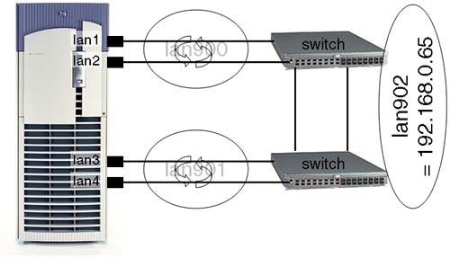
A human-readable interpretation of this could be:
lan900is a load balancing aggregate made up of a number (two, in this case) of individual interfaces.lan901is a load balancing aggregate made up of a number (two, in this case) of individual interfaces.We apply our IP configuration to
lan900;lan901will be our Standby interface in the event of a failure oflan900.lan902is a Failover Group consisting of two interfaces:lan900andlan901.We are using interconnected switches to avoid the switch being a Single Point Of Failure.
If we were really clever with our hardware configuration (and our server supported it), we could choose LAN cards located in different IO cardcages (but that only really applies to partitionable servers). Let's look at putting this configuration into practice. First, we create our load balancing aggregates:
root@hpeos003[lanmon] vi /etc/rc.config.d/hp_apaportconf
...
#####################################################################

HP_APAPORT_INTERFACE_NAME[0]=lan1
HP_APAPORT_CONFIG_MODE[0]=MANUAL

HP_APAPORT_INTERFACE_NAME[1]=lan2
HP_APAPORT_CONFIG_MODE[1]=MANUAL

HP_APAPORT_INTERFACE_NAME[2]=lan3
HP_APAPORT_CONFIG_MODE[2]=MANUAL

HP_APAPORT_INTERFACE_NAME[3]=lan4
HP_APAPORT_CONFIG_MODE[3]=MANUAL

##########################################################################
#  The HP_APAPORT_INIT_ARGS are reserved by HP. They are NOT user changable.

HP_APAPORT_INIT_ARGS="HP_APAPORT_GROUP_CAPABILITY HP_APAPORT_PRIORITY HP_APAPORT_CONFIG_MODE HP_APAPORT_KEY HP_APAPORT_SYSTEM_PRIORITY"

# End of hp_apaportconf configuration file
root@hpeos003[lanmon]
In my case, I am using MANUAL port mode. I would change this as appropriate for the switch I was using, i.e., FEC_AUTO or LACP_AUTO. I can now define my lan900 and lan901 aggregates:
root@hpeos003[lanmon] vi /etc/rc.config.d/hp_apaconf
#####################################################################

HP_APA_INTERFACE_NAME[0]=lan900
HP_APA_LOAD_BALANCE_MODE[0]=LB_MAC
HP_APA_HOT_STANDBY[0]=off
HP_APA_MANUAL_LA[0]="1,2"

HP_APA_INTERFACE_NAME[1]=lan901
HP_APA_LOAD_BALANCE_MODE[1]=LB_MAC
HP_APA_HOT_STANDBY[1]=off
HP_APA_MANUAL_LA[1]="3,4"


###########################################################################
#  The HP_APA_INIT_ARGS are reserved by HP. They are NOT user changable.
HP_APA_START_LA_PPA=900
HP_APA_DEFAULT_PORT_MODE=MANUAL

HP_APA_INIT_ARGS="HP_APA_LOAD_BALANCE_MODE HP_APA_GROUP_CAPABILITY HP_APA_HOT_STANDBY HP_APA_MANUAL_LA HP_APA_INIT HP_APA_KEY"

# End of hp_apaconf configuration file
root@hpeos003[lanmon]
I can now apply this part of the configuration:
root@hpeos003[lanmon] /sbin/init.d/hplm stop
DLPI version is 2
Clearing Fail-Over Group lan900
Deleted binary file /etc/lanmon/lanconfig
         /sbin/init.d/hplm stopped.
root@hpeos003[lanmon] /sbin/init.d/hpapa stop
DLPI version is 2
         /sbin/init.d/hpapa stopped.
root@hpeos003[lanmon]
root@hpeos003[lanmon] ifconfig lan1 unplumb
root@hpeos003[lanmon] ifconfig lan900 unplumb
root@hpeos003[lanmon] /sbin/init.d/hpapa start
DLPI version is 2
         /sbin/init.d/hpapa started.
         Please be patient. This may take about 40 seconds.
         HP_APA_MAX_LINKAGGS = 50
         HP_APA_DEFAULT_PORT_MODE = MANUAL
         /usr/sbin/hp_apa_util -S 1 MANUAL
         /usr/sbin/hp_apa_util -S 2 MANUAL
         /usr/sbin/hp_apa_util -S 3 MANUAL
         /usr/sbin/hp_apa_util -S 4 MANUAL
lan900
         /usr/sbin/lanadmin  -X -l LB_MAC 900
         New Load Balancing = 2
         /usr/sbin/lanadmin  -X -y off 900
         New Hot Standby = OFF
         /usr/sbin/lanadmin  -X  -a 1 2 900
         Added ports:1 2 to lan900
lan901
         /usr/sbin/lanadmin  -X -l LB_MAC 901
         New Load Balancing = 2
         /usr/sbin/lanadmin  -X -y off 901
         New Hot Standby = OFF
         /usr/sbin/lanadmin  -X  -a 3 4 901
         Added ports:3 4 to lan901
         /sbin/init.d/hpapa Completed successfully.
root@hpeos003[lanmon]
I should now have two aggregates up and running.
root@hpeos003[lanmon] lanscan
Hardware Station        Crd  Hdw   Net-Interface    NM   MAC     HP-DLPI DLPI
Path     Address        In#  State NamePPA          ID   Type    Support Mjr#
0/0/0/0  0x00306E5C3FF8 0    UP    lan0 snap0       1    ETHER     Yes   119
LinkAgg0 0x00306E467BF0 900  UP    lan900 snap900   8    ETHER     Yes   119
LinkAgg1 0x00306E467BF2 901  UP    lan901 snap901   9    ETHER     Yes   119
LinkAgg2 0x000000000000 902  DOWN  lan902 snap902   10   ETHER     Yes   119
LinkAgg3 0x000000000000 903  DOWN  lan903 snap903   11   ETHER     Yes   119
LinkAgg4 0x000000000000 904  DOWN  lan904 snap904   12   ETHER     Yes   119
root@hpeos003[lanmon] lanadmin -x -v 900
Link Aggregate PPA #      : 900
Number of Ports           : 2
Ports PPA                 : 1 2
Link Aggregation State    : LINKAGG MANUAL
Group Capability          : 5
Load Balance Mode         : MAC Address based (LB_MAC)

root@hpeos003[lanmon] lanadmin -x -v 901
Link Aggregate PPA #      : 901
Number of Ports           : 2
Ports PPA                 : 3 4
Link Aggregation State    : LINKAGG MANUAL
Group Capability          : 5
Load Balance Mode         : MAC Address based (LB_MAC)

root@hpeos003[lanmon]
We can now apply our IP configuration to lan900:
root@hpeos003[lanmon] ifconfig lan900 192.168.0.65 netmask 255.255.255.224
root@hpeos003[lanmon] ifconfig lan900
lan900: flags=843<UP,BROADCAST,RUNNING,MULTICAST>
        inet 192.168.0.65 netmask ffffffe0 broadcast 192.168.0.95
root@hpeos003[lanmon] netstat -in
Name      Mtu  Network         Address       Ipkts   Ierrs Opkts   Oerrs Coll
lan0:1    1500 192.168.0.0     192.168.0.13  11      0     23      0     0
lan0      1500 192.168.0.32    192.168.0.33  12321   0     8068    0     138
lo0       4136 127.0.0.0       127.0.0.1     118     0     118     0     0
lan900    1500 192.168.0.64    192.168.0.65  9       0     9       0     0
root@hpeos003[lanmon]
To ensure that this IP configuration works over reboots, I would update my /etc/rc.config.d/netconf file to reflect the ifconfig command above. Next is to set up and apply the Failover Group configuration:
root@hpeos003[lanmon] vi lanconfig.ascii

# ********************************************************
# *********** LAN MONITOR CONFIGURATION FILE *************
# *** For complete details about the parameters and how **
# *** to set them, consult the lanqueryconf(1m) manpage **
# *** or your manual.                                **
# ********************************************************

NODE_NAME                       hpeos003
POLLING_INTERVAL                10000000
DEAD_COUNT                      3

FAILOVER_GROUP                  lan902
        STATIONARY_IP   192.168.0.65
        PRIMARY         lan900    5
        STANDBY         lan901    3

root@hpeos003[lanmon]
root@hpeos003[lanmon] /sbin/init.d/hplm start
DLPI version is 2
         /sbin/init.d/hplm started.
Reading ASCII file /etc/lanmon/lanconfig.ascii
Creating Fail-Over Group lan902
Updated binary file /etc/lanmon/lanconfig
         /sbin/init.d/hplm Completed successfully.
root@hpeos003[lanmon]
I should have lost lan900 and lan901 as individual interfaces, but gained a lan902 interface configured with my IP address:
root@hpeos003[lanmon] lanscan
Hardware Station        Crd  Hdw   Net-Interface    NM   MAC     HP-DLPI DLPI
Path     Address        In#  State NamePPA          ID   Type    Support Mjr#
0/0/0/0  0x00306E5C3FF8 0    UP    lan0 snap0       1    ETHER     Yes   119
LinkAgg2 0x00306E467BF0 902  UP    lan902 snap902   10   ETHER     Yes   119
LinkAgg3 0x000000000000 903  DOWN  lan903 snap903   11   ETHER     Yes   119
LinkAgg4 0x000000000000 904  DOWN  lan904 snap904   12   ETHER     Yes   119
root@hpeos003[lanmon]
root@hpeos003[lanmon] netstat -in
Name      Mtu  Network         Address       Ipkts   Ierrs Opkts   Oerrs Coll
lan0:1    1500 192.168.0.0     192.168.0.13  11      0     23      0     0
lan0      1500 192.168.0.32    192.168.0.33  12580   0     8229    0     143
lo0       4136 127.0.0.0       127.0.0.1     118     0     118     0     0
lan902    1500 192.168.0.64    192.168.0.65  14      0     12      0     0
root@hpeos003[lanmon]
root@hpeos003[lanmon] lanadmin -x -v 902
Link Aggregate PPA #      : 902
Number of Ports           : 2
Ports PPA                 : 900 901
Link Aggregation State    : LINKAGG MANUAL
Group Capability          : 2043239264
Load Balance Mode         : Hot Standby (LB_HOT_STANDBY)

root@hpeos003[lanmon]
We have a load balancing aggregate (lan900) maximizing the throughput of multiple interfaces. Should we lose both ports that constitute lan900, we will fail over to lan901. I quite like this configuration.
Configuring LAN interfaces with IP addresses is a fundamental task of any UNIX administrator. We have looked at key technologies that go beyond simply configuring the netconf file. DHCP is becoming more and more common, especially where remote users are logging in to our networks and need an IP configuration in order to function. We have looked at how DHCP affects the way we manage IP addresses, as well as the emergence of IPv6. Finally, we looked at trying to provide a networking nirvana of both High Availability and Performance utilizing APA. It's all in a day's work.
Looking at Figure 15-6, we have two machines each with four LAN cards. How many | |
We have changed the MAC address of one of our nodes (on network-1). It transpires that we have chosen a real MAC address belong to a machine that is located on network-25 (see Figure 15-7). Both machines have different IP/Network addresses but share the same MAC address. The routers called router1 and router15 use dynamic routing to communicate with all other routers in the corporate Intranet. Will nodes Fin100 and Corp100 be able to communicate even though they have the same MAC address? Explain your answer. | |
I am subnetting my corporate Intranet and realize that I need 16 networks. I have control over the entire Class C address 192.168.128.0. What should my subnet mask be? How many nodes will I be able to configure per subnet? What is the network address of these two nodes?
| |
Why might it take some time before we see many more devices on the Internet using IPv6 addresses? Take this MAC address, | |
Give a reason why you think we cannot mix link technologies in a single APA aggregate, e.g., FDDI interfaces alongside 100-BaseT interfaces. What does APA LAN Monitor mode do differently from APA Hot Standby in order for LAN Monitor mode to be able to detect link failures across the entire aggregate quicker? |