
Chapter 6. Blinky Pi
In this chapter, you’ll be learning about
- Giving your Pi the ability to talk to the outside world through connectors to anything
- Programming the world outside your Pi with simple electric/electronic circuits
- Programming the connectors using your previous Python knowledge to make light patterns
Setting robots in motion, creating smart homes with sensors, and designing an interactive electronic art exhibit sound like vastly different topics, but they’re all things you can do with your Raspberry Pi. In each case, the Pi can act as the brain and interact with the world by doing things like
- Checking a robot’s sensors and controlling its motors
- Sensing a room’s occupants and adjusting the thermostat or lights
- Controlling sound, motion, and light as part of an art display
In this chapter, you’ll set up your Pi to control small light bulbs called light-emitting diodes (LEDs). You’ll make the LEDs blink using Python. To do this, you’ll need to learn a bit about how to build electrical circuits on breadboards. If you’ve never heard of a breadboard, don’t worry! It’s a small board with lots of holes in it to make it easier to build electrical circuits. You’ll also be using short wires (called jumper wires) to connect certain holes. You’ll even learn how to add resistors that keep your LEDs from burning out. See figure 6.1 for a list of parts and what they look like; gather the parts, and let’s get started!
Figure 6.1. The Blinky Pi project requires parts that are commonly found in Raspberry Pi starter kits or that can be purchased online.

Setting up your Pi for physical computing
Your Pi is unique compared to most computers because of its input and output pins, called GPIO pins. Let’s learn how to work with those pins.
Definition
GPIO stands for general purpose input and output. These are the pins on your Raspberry Pi that allow it to sense and control things around it.
GPIO pins
The Raspberry Pi 2 Model B and Raspberry Pi 1 Model B+ have 40 pins located on the edge of the board, arranged in 2 rows of 20 pins each (see figure 6.2). Most of the pins on a Pi are used for input and output, so they’re often referred to as the Pi’s GPIO pins.
Figure 6.2. The Raspberry Pi 2 Model B has a set of pins arranged along the edge and corner of the Pi board.

Warning
This project is written for Raspberry Pi 2 Model B. Earlier models of the Raspberry Pi have only 26 pins. See appendix B for information about the differences from the more modern Pi boards. To complete this project with a Raspberry Pi 1 Model B, you may select different pins to light up your LEDs.
Because all the pins look identical, you need a key or diagram to tell you what each one does. Figure 6.3 shows the pins labeled.
Figure 6.3. The Raspberry Pi B+ has 40 pins. They do different things: some provide 5 volts or 3.3 volts, some are ground pins (0 volts), and many of them are input and output pins that you can program.

In this book, we’ll always refer to the GPIO pin numbers, not the physical pin locations. The physical pins are numbered from 1 to 40 (shown in the circles in figure 6.3). The GPIO pin numbers go from 1 to 26, and those numbers don’t match the physical pin numbers. For example, GPIO 24 corresponds to physical pin 18. By always using the GPIO numbering, it will be easier to wire your circuits and create programs.
Wow, that’s a lot of pins! Some pins are for power and are labeled either 3V3 or 5V. These produce 3.3 volts or 5 volts, respectively. There are also 8 ground pins and 26 GPIO pins[1]—26 pins, just like there are 26 letters in the alphabet.
Oddly, you’ll notice that the GPIO pins are numbered from 2 to 27. Pins 0 and 1 are used for communicating with other computer chips using a super-special protocol called I2C. These are labeled ID SDA and ID SCL in figure 6.3.
The GPIO pins support sending out electrical signals (output) or listening for electrical signals from sensors (input). In your body, your brain can send signals to your hand to smack yourself on the forehead (try it!)—this is just like the output from a Pi. Signals are sent out of your Pi to make something happen in the world.
The opposite of output is input. When someone pokes you, your body can detect that poke using nerves in your body. An electrical signal (input) is sent to your brain so you know you’ve been poked. This is like the way your Pi can be used to detect input or actions in the world.
You’ll learn how to output signals in this chapter and chapter 7. Chapter 8 will cover detecting input from the world, such as detecting when a button has been pressed.
Let’s get ready to connect some wires! But wait: connecting an LED directly to the GPIO pins on the board of your Raspberry Pi isn’t feasible, because the pins are so close together. What can you do? You need more space to build circuits.
Breaking out the GPIO pins to a breadboard
To give you room, you’ll move the GPIO pins over to a breadboard. This is called breaking them out. To do this, you need a ribbon cable, breakout board, and solderless breadboard (see figure 6.4).
Figure 6.4. To easily create projects using your Pi’s GPIO pins, you can connect the Pi to a breadboard using a ribbon cable and breakout board. The parts shown are examples of the ones commonly found in many Raspberry Pi kits.

Breadboards make it simple to prototype circuits. Like a park might provide large, open fields that make it easy to play sports, think of a breadboard as a nice, open electrical playing field where you can play with electrical parts. The breadboard allows you to plug wires and components into small holes. You can build and rebuild circuits on a breadboard with little effort.
Find your breakout board, and insert it into the top of the breadboard. Line up the pins before you push it down hard (see figure 6.5). Your particular breakout board may look a little different, but they all act the same. With the breakout board in place, it’ll be easier to build circuits with your GPIO pins.
Figure 6.5. Carefully line up the breakout board, and then press it firmly into the breadboard. The two rows of pins on the breakout board should straddle the center gap.

Connect one end of the ribbon cable to the Pi’s GPIO pins; line it up carefully before you push it down. Then connect the other end of the cable to the breakout board on your breadboard (see figure 6.6). A breakout board has a notch in it so the ribbon cable will only fit one way.
Figure 6.6. Connect one end of the ribbon cable to the breakout board. Connect the other end to your Raspberry Pi.

Warning
Ribbon cables usually have a stripe that marks the first wire. White or grey ribbon cables often use a red stripe. Black ribbon cables often have a white stripe. These mark the first wire on the cable. Make sure this first wire is connected toward the edge of your Pi’s board and away from the USB ports.
Breadboard basics
A breadboard[2] has a set of internal connections that you can’t see. But if you had X-ray vision, you’d see that certain holes are connected. Let’s look at the connections in your breadboard (see figure 6.7).
Prior to the development of the kind of breadboards we’re using, people built circuits on pieces of wood that were used to cut bread on (hence the name). They needed a quick way to connect circuits, and by drilling holes and using nails and wires, they could use bread boards to try different circuits.
Figure 6.7. Breadboards have internal connections. You need to know about them in order to build circuits. Rows of pins are connected horizontally, but not across the gap in the middle. Long rails called power buses run vertically along the sides of the board.
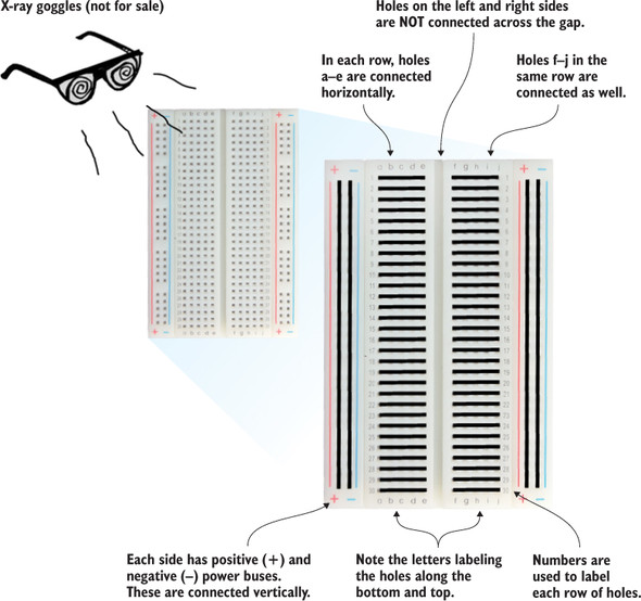
On this breadboard, rows are labeled with numbers (1–30), and the columns have letters (a–e on the left side and f–j on the right side). You can refer to a specific hole in the breadboard by saying its row number and letter. For example, if you wanted to refer to the hole located in row 25, column c, you could say 25c (see figure 6.8). Just as you might find your seat at a stadium by walking along the aisle to find the correct row, and then moving along the row to find the right seat, you’ll use the letters and numbers to guide you in building your circuits.
Figure 6.8. To find a specific hole on a breadboard, use the row and column labels. This is a close-up of a breadboard, showing how you can find the location of hole 25c (we’ll refer to the hole as BB25c, where BB stands for breadboard).

Breadboard (BB) holes
We’ll refer to the row and column, but we’ll prepend the letters BB so you know it’s the breadboard location we’re talking about. Figure 6.8 shows the location of BB25c. If we’re talking about a GPIO pin or connection, we’ll add GP before the number (GPIO pin 21 is GP21).
Try to keep in mind what is connected in a breadboard and what isn’t. If you forget, you can always look back at figure 6.7. For example, notice that BB25 a, b, c, d, and e are all connected. Similarly, BB30 f, g, h, i, and j are connected. But the left side of the board isn’t connected to the right. For example, BB25e isn’t connected to BB25f. To connect them, you’d put a jumper from BB25e to BB25f.
You can see vertical columns of holes along the sides of the breadboard. These are the power buses and provide easy ways to connect electrical components to power (positive) and ground (negative).
Let’s learn about electricity and circuits. At the simplest level, a circuit is a loop or path where the electrical power starts at a source (the positive side of a power source), goes through one or more electrical components (such as a light or motor), and then completes the loop (or path) by connecting back to the negative side of the source.
WHAT IS ELECTRICITY?
Electricity is the flow of charge. Typically, it is the flow of electrons, which have a negative charge. To get electrons to flow, you need to have a difference in charges. Just as the north pole of a magnet is attracted to its opposite—the south pole of another magnet—positive and negative electric charges are attracted to one another. If the charge is free to move, it will move. We generally think of circuits as having electricity flowing from the positive (+) side of the source to the negative (-) side of the source. For your Pi, the power is coming from the power supply (Micro USB plug). The Pi as a power source can provide either +3.3 volts or +5 V (volts). It provides this power through the physical pins 1, 2, and 4, but can also send +3.3 V out any of the 26 GPIO pins (you’ll program it to do that soon).
VOLTAGE (VOLTS)
Voltage is a measure of the difference in electrical charge between the positive and negative source. When you have two different charges, they’re attracted to one another (positive and negative attract). The greater the difference in charge, the greater the force (or electrical pressure) wanting to move charges through the circuit from the positive side to the negative side.
Voltage is measured in volts (V), named after Alessandro Volta, who is credited with inventing the first battery. A 9 volt (or 9 V) battery has a greater electric force for moving charge than a AA battery, which only has a voltage of 1.5 V.
CURRENT (AMPERES)
The current in a circuit is the amount of charge flowing. So whereas voltage is a measure of how badly charges want to flow, the current is a measure of how much charge is actually flowing.
Imagine that you could be inside a wire and see the charge flowing through it. A large current would mean a lot of charge (usually electrons) bumping along and through the wire over some period of time. A small current in that same wire would mean a lot less charge flowing over that same time period. Current is measured in amperes (A), named after André-Marie Ampère. A current of 1 ampere (or 1 A) is equivalent to the amount of charge of 6.241 × 10¹⁸ electrons flowing through a wire per second! That is a lot of charge flowing. You can decrease the current in a circuit by increasing the resistance of the circuit to the flow of electric charge.
RESISTANCE (OHMS)
The resistance in a circuit is a measure of how much it opposes the flow of charge (current). A light bulb, a motor, and your body all have resistance. The opposite of resistance is conductance. Substances such as metal (copper, silver, and gold) are all good conductors, and this is why we build circuits with metal wires for the electricity to flow through.
Sometimes you need to control the current (the flow of charge). Resistors are used to do this; they’re made of materials that slow down the flow of charge. The most common ones are made out of carbon (you’ll be using these in your projects). The resistance of a circuit is measured in ohms, named after Georg Ohm, and is represented using the Greek symbol omega (Ω).
PI CIRCUITS
You can think of your Pi as providing 3.3 V from the positive side of the Pi or, later, coming out of one of the GPIO pins. This +3.3 V is a force that is trying to push electric charge to the negative (-) side of your source. The negative side is sometimes called the ground—think of it as a big sink or reservoir to which electricity wants to flow if there is a path to get there. During the next few chapters, you’ll build circuits with LEDs and resistors. You use a resistor with an LED to decrease the flow of electric charge (the current) so it won’t be too large and burn out your LED. Burning an LED smells bad!
On your breadboard, think of all the GPIO pins as potential sources of voltage (positive). Circuits from the GPIO pins should end back at any one of the many ground (negative) connections.
Building the LED circuit
Your first project is to light up a red LED. You’ll control the LED using GPIO pin 21 (GPIO21). You need these parts:
- Raspberry Pi, ribbon cable, and breakout board connected to your breadboard
- 1 red LED (5 mm)
- 1 180 ohm resistor
- 1 jumper wire (male-to-male)
You’ll build the LED circuit on your breadboard and then program it to light up. Figure 6.9 shows the circuit diagram. To light the LED, you’ll have electricity (+3.3 V) flow from your Pi’s GPIO pin 21 through the LED, through the resistor, and then to ground (0 V).
Figure 6.9. Circuit diagram for the blinking LED project

Figure 6.10 shows the LED circuit built on the breadboard. Note that there are many different ways to create this circuit—this is just one way. Let’s walk through the steps to build the circuit.
Figure 6.10. LED circuit built on the breadboard. You’re using GPIO pin 21 as the power source. The light won’t turn on until you program the voltage to come out of the pin.

Note
You may have a different breadboard than the one used in this book. If so, the numbering on your breadboard may be different than what is shown here. In that case, you’ll need to create the circuit following the same principles, but with different numbered holes.
Step 1. Connect the jumper from GPIO pin 21
Raspberry Pi GPIO pins can output 3.3 V. You could pick any pin, but this project uses GPIO pin 21.
Connect a short piece of wire from GPIO21 on your breadboard to an empty row on the breadboard. Use row 25. Firmly push the wire into the hole. The metal tip of the wire should go down into the hole, not sit on top.
The breakout board pins are connected to rows on the breadboard. We’ll refer to the holes on the breadboard (see figure 6.11). Insert one end of the jumper into BB20i and the other end into BB25a.
Figure 6.11. The breakout board has labels that correspond to the pins on your Pi. To connect a wire to GP16, you plug it into the breadboard in the hole labelled BB18f or BB18j.

Step 2. Add the red LED
It’s time to connect the red LED. LEDs only let electricity flow through them one way, so it’s important to put them in the right way. LEDs have two wires or legs. The longer leg is called the anode and connects to the positive side of the circuit (see figure 6.12). The shorter leg, called the cathode, connects to the negative or ground side of the circuit.
Figure 6.12. LEDs have two legs (wires) coming out of them. The longer leg is called the anode and connects to the positive side of the circuit. The shorter one is called the cathode and connects to the negative side of a circuit.

With the red LED, connect the longer leg to BB25e and the shorter leg to BB25f. You may need to bend the legs and push them a bit to get them into the holes.
Step 3. Connect a resistor
Grab your 180 ohm resistor.[3] You can identify a resistor by its color-coded bands. A 180 ohm resistor has colored bands of brown, grey, and brown (see figure 6.13). They are followed by a fourth band that indicates the tolerance or quality of the resistor. Common colors for the fourth band are gold (±5% tolerance) and silver (±10% tolerance).
If you don’t have a 180 ohm resistor, you can use a resistor with a value between 100 and 330 ohms. If you use a resistor with a value that is too large, the LED may not light up or will be dim. Try experimenting with different resistors to adjust the brightness.
Figure 6.13. The value of a resistor is determined by its colored bands. See the sidebar “Resistor color codes” for a chart; there are also many online color-code charts.

The resistor prevents too much electric current[4] from passing through your LED and burning it out. Insert one end of the 180 ohm resistor into BB25j and the other end into the negative (-) power bus (or ground).
Current is a measure of the flow of electric charges per second. If the current through an LED is too high, the LED will burn out.
Electricity will flow either way through a resistor, so which way you connect it doesn’t matter. Remember that the negative power bus or ground rail is running vertically along the right side of the breadboard. Most boards have a blue stripe next to it.
Resistors have color codes that tell their value and tolerance. This chart shows you how to read the resistor color bands.

For example, consider a resistor with red, purple, red, and silver bands. Follow these steps to use the chart:
- Look up the digit for the first band and the digit for the second band, and put them together. In this case, the digits are 2 and 7: put them together, and you get 27. Note that you don’t add the numbers; you treat them as the first and second digits of the resistor value.
- Find the multiplier by looking up the color for the third band. In this case, it’s 100 ohms (red).
- Put it all together: 27 × 100 ohms is 2,700 ohms or 2.7K ohms (K = 1,000).
- The fourth band (silver) tells you the resistor has a tolerance of ±10%.
A red, purple, red, and silver resistor is a 2.7K ohm resistor with a ±10% tolerance. Use this handy chart any time you need to look up the value of a resistor.
That’s it! You have a completed LED circuit built on your breadboard. Now it’s time to program it!
Software: blinkLED program
Open IDLE by choosing Python 3 under Menu > Programming. This opens IDLE to the Python 3.x Shell. In the Python Shell, let’s check to see if your Pi has the GPIO libraries you need already installed:
>>> import RPi.GPIO as GPIO
If you don’t see an error, you’re ready to go. If you see an error saying there is no module named RPi.GPIO, please refer to the sidebar “Updating your Pi.”
Before programming, you need to check that your Pi is up to date. Make sure your Pi is connected to the internet. Open the Terminal program by going to Menu --> Accessories --> Terminal, and run the following commands to update your Raspberry Pi and be certain you have the Raspberry Pi GPIO packages you need.
First, let’s update the apt-get database. The apt-get program handles installing and removing software from your Pi. In Terminal, enter this command:
pi@raspberrypi ~ $ sudo apt-get update
You’ll need to wait while a bunch of files are downloaded and installed. You’ll see lots of messages displayed in Terminal. When the command completes, you’ll see the Terminal $ prompt again. Next, to get the latest Pi software, enter
pi@raspberrypi ~ $ sudo apt-get upgrade
Once again, files will be downloaded and installed. After a series of messages, you’ll see a warning about the upgrade using additional disk space, and this prompt: “Do you want to continue [Y/n]?” Enter Y and press Enter to continue the upgrade.
This is a great time to grab a sandwich and soda. It can take 15 minutes or more for the update to complete. When it’s finished, you’ll have the latest Raspberry Pi software and Python libraries, including the ones you need to communicate with and control the GPIO pins.
You’re going to write a program that blinks an LED. It’ll send a voltage (+3.3 V) out of a GPIO pin to light the LED, then turn it off, and repeat that over and over. Begin by creating the following new program in IDLE. In the Python Shell, start a new program by pressing Ctrl-N or selecting File > New Window.
Listing 6.1. Blinking LED program

Save the program as blinkLED.py in your home folder. The program can’t be run the same ways you’ve run programs before using IDLE.
Running the program
Select Run > Run Module (or press F5) from the IDLE text editor to run your program. With older versions of Raspbian, programs using GPIO pins must be run from the Raspbian command prompt as the superuser (or root)[5]. If you run the program at the Python Shell in IDLE, you’ll get an error:
In October 2015, the Raspberry Pi Foundation released Raspbian version “Jessie,” which allows you to run programs using the GPIO pins directly from IDLE. With “Jessie” you don’t need to open the command prompt. Simply press F5 or select Run > Run Module from the IDLE text editor menu to run your programs.
RuntimeError: No access to /dev/mem. Try running as root!
In this case, you use the sudo command to do this. To run the blinkLED.py program, open LXTerminal and enter the following command:
pi@raspberrypi ~ $ sudo python3 blinkLED.py
Behold the blinking LED! Try making the light blink faster by adjusting the value in the sleep function. Use a smaller number of seconds, such as 0.5 or 0.1.[6] To stop the program, press Ctrl-C.
Too small a number may cause the light to appear to stay on, but more dimly. This is because your eyes can only perceive blinking that is greater than about 1/25th of a second, or 0.04 of a second.
Note
Stopping the program with Ctrl-C may result in the light being left on (depending on when you press it). Also, the next time you run the program, you may see a runtime error, but the program still works. We don’t cover it here, but look online for the Python commands try/except/finally and the GPIO.cleanup() command. It’s a fancy way to make sure all the GPIO pins are reset when you exit the program.
Troubleshooting
If the light isn’t blinking, here are some things you can check:
- Are the on and off messages displaying on the screen? If so, it’s probably not your code that has a problem. Check the circuit on the breadboard. Make sure the ribbon cable is connected properly, with the first wire connected toward the edge of your Pi, away from the USB ports. Double-check that the jumper, LED, and resistor are connected to the correct holes.
- Could your LED be inserted the wrong way? Make sure the shorter leg is toward the negative or ground side. Try turning it around.
- Double-check the size of the resistor you used in the circuit. If the resistor is too large, the LED won’t light up. A resistor that is between 100 and 300 ohms should work.
- Look through your Python program for errors. Check that you have set LED_pin_red equal to 21 and that you’re setting it HIGH and then LOW.
blinkLED: how it works
Let’s take a closer look at how the blinkLED.py code works.
Loading libraries
The import commands load the libraries or toolboxes you want to use in your program:
import RPi.GPIO as GPIO
import time
These commands load the Python libraries for controlling the Pi’s GPIO pins. They also load the time library so you can use the sleep function to control the rate of blinking.
Notice the as keyword in import RPi.GPIO as GPIO. Why can’t you just type import RPi.GPIO?
The as keyword tells Python to load the library to a certain name you specify. It’s kind of like giving the whole library a nickname. In this case, it’s so you can refer to RPi.GPIO as simply GPIO.
An example will make it clearer. Once you’ve imported the RPi.GPIO library as GPIO, you can type GPIO.setmode(GPIO.BCM). Without it, you would have to type RPi.GPIO.setmode(RPi.GPIO.BCM). You can see how using as GPIO saves you some typing!
Once the libraries are loaded, you can set up your GPIO pins.
Setting up a GPIO pin for output
To set up a GPIO pin, you first need to tell Python on your Pi that you’ll be referring to pins by the standard breakout numbering scheme. These are the numbers printed on the breakout board. You use the setmode function:
GPIO.setmode(GPIO.BCM)
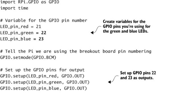
BCM stands for Broadcom—the maker of the computer chip that the Pi uses. Next you tell your Raspberry Pi that you’ll be using LED_pin_red (GP21) for output, meaning you’re planning to send some electricity out of it:
LED_pin_red = 21

GPIO.setup(LED_pin_red, GPIO.OUT)
GPIO.OUT prepares GP21 to send out +3.3 V of electricity.
Looping and blinking
Finally, you create an infinite while loop and turn the LED on (set GPIO.HIGH) and off (set GPIO.LOW). You also add a delay using the sleep method found in Python’s time library. Notice how the sleep function takes a parameter that is the number of seconds to sleep or pause. In this case, you use 1 second:
while True:
    GPIO.output(LED_pin_red, GPIO.HIGH)
    print("On")
    time.sleep(1)
    GPIO.output(LED_pin_red, GPIO.LOW)
    print("Off")
    time.sleep(1)
The print commands display messages to the screen. Although they aren’t necessary to blink the LED, they can help debug your program. If you do use them, the screen could quickly fill with messages. Set a longer delay time to prevent this. If you see the messages on the screen but your LED isn’t lighting up, then you probably have an error in your circuit and not in your program. Check your wiring, try turning around the LED, or try a different LED in case that one is defective.
Adding more LEDs
One LED is fun, so three LEDs must be lots of fun. Let’s try adding green and blue LEDs and modify the program to control them. Here are the parts you need:
- Raspberry Pi and circuit from before
- 1 green LED
- 1 blue LED
- 2 180 ohm resistors
- 2 jumper wires (male-to-male)
Building the circuit
You’ll follow the same process as before to add the green and blue LEDs. Figure 6.14 shows what the circuit diagram looks like now, and figure 6.15 shows the circuit on a breadboard.
Figure 6.14. Circuit diagram for three LEDs: red, green, and blue. You’ll use 180 ohm resistors like before. They will all be controlled by different GPIO pins. Red will use 21, green will use 22, and blue will be connected to pin 23. You could use any of the 26 different GPIO pins.

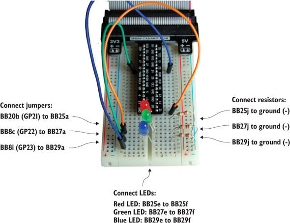
Figure 6.15. The three-LED circuit is built on the breadboard. Each LED and its corresponding resistor are placed in a row together. This example uses rows 25, 27, and 29.
To add the green LED, follow these steps:
1. GP22 is located on the left side of the breakout board in row 8 on the breadboard. Connect it to row 27: insert one end of the jumper into BB8c and the other end into BB27a.
2. Connect the long leg of the green LED to BB27e and the shorter leg to BB27f. Bend the legs if needed.
3. Connect a 180 ohm resistor (brown, grey, and brown) from BB27j to the closest hole in the negative power bus.
Here are the steps to add the blue LED:
1. GPIO23 is located on the right side of the breakout board in row 8 on the breadboard. Connect it to row 29: insert one end of the jumper into BB8i and the other end into BB29a.
2. Connect the long leg of the blue LED to BB29e and the shorter leg to BB29f. Bend the legs if needed.
3. Grab a 180 ohm resistor. You guessed it! It’s color-coded brown, grey, and brown. Connect it from BB29j to the closest hole in the negative power bus.
Multiple LEDs: program it!
You need to make a few changes to the program to add more LEDs and get them all blinking at the same time. The following listing shows the updated code.
Listing 6.2. Three blinking LEDs

Save the code as blinkLED3.py, and try running it. Open LXTerminal, and enter the following command:
pi@raspberrypi ~ $ sudo python3 blinkLED3.py
Fantastic! You have your own light show going on!
![]()
Challenges
Try these challenges to practice controlling your Raspberry Pi’s GPIO pins. Each one provides a unique problem to solve.
Wave pattern
Change the program to make each LED turn on, one at a time, until they’re all on. Then, turn each LED off, one at a time. Hint: play with where you put the time.sleep(1) command. Can you make the LEDs light up and turn off in a wave pattern?
Simon Says
Write a function that blinks the LEDs and that can take five parameters representing a pattern of colorful blinks. Each parameter is a string representing a color: red, blue, or green. The function should blink the lights in the appropriate pattern. Here is a series of Simon Says patterns you should try to make your function produce:
Red, green, red, red, blue
Blue, green, blue, green, red
Green, blue, blue, red, green
Random blinking
Create a program that generates random durations for how long the lights stay on and off. The durations should be random floating-point numbers between 0 and 3 seconds. Hint: you can use the random method to generate a random floating-point number between 0 and 1.0. Here is an example:
off_random_time = random.random() * 3
To scale this number so that it’s between 0 and 3, you can multiply off_random_time by 3. If you get stuck on the challenge, check appendix C and the chapter source code for hints and solutions.
Summary
In this chapter, you learned the following things:
- A Pi is capable of interacting with the world around it. With a few extra parts, you can set it up for physical computing projects.
- A Pi can send out electrical signals! You can send output through the GPIO pins, and this can be used to light up LEDs or control many other electronic components (motors, buzzers, relays, and so on).
- Breadboards are like playgrounds for electronics. They make it easy to create circuits for your Pi because you can easily build and take apart circuits for use with the Pi.
- The RPi.GPIO library has built-in functions to set up and control output (voltage) to GPIO pins with Python.
Just imagine the possibilities of controlling pretty much any electrical device using your Raspberry Pi. Even better, imagine making the device work based on sensors (inputs) so you can create smart devices programmed by you!