Chapter 7. Light Up Guessing Game
In this chapter, you’ll be learning about
- Simplifying and improving your code with more thoughtful design and use of functions
- Building a circuit to control a special LED (light bulb) that can make and combine red, green, and blue light
- Adding together colors of light to create new colors
- Making your Pi come alive by having it respond using different colored light
Your Raspberry Pi has a unique ability to interact with the world around it. In the last chapter, you made lights blink based on a programmed pattern. Nice, but that isn’t truly interactive, because the Pi always blinks a pattern that you program it to do. In this chapter, let’s see if you can create an interactive project that responds to you through its GPIO pins. You’ll draw on what you’ve learned about conditional logic (if/elif/else) to have your Pi make decisions and respond. As you did in earlier chapters, you’ll need to gather input, use loops, and apply a few other programming techniques to get it done.
You’re making a Light Up Guessing Game, but not just any one: this game will illuminate a small light called an RGB (stands for red, green, blue) LED, which can make any color. You’ll use your Pi, breadboard, and electrical parts, along with a program you’re going to write. Your Pi will let the player know if they’re correct by flashing the RGB in different colors if their guess is too high or too low.
Figure 7.1 shows the parts you need. You’ll notice that some of them are the same as in chapter 6, but you’ll also need an RGB LED. Let’s get started!
Figure 7.1. The Light Up Guessing Game uses a red, green, blue (RGB) LED. An RGB LED can produce many different colors because it has three LEDs (colored red, green, and blue) packed inside it.

Guessing Game design
The object of the game is to guess a magic number. This time, the Pi will give feedback to the user by lighting up the RGB LED in different colors. Here are some game details:
- The magic number is a randomly generated number between 1 and 20.
- The player is given five tries to guess the number correctly.
- If they guess correctly, the RGB LED flashes green.
- If the guess is too high, the RGB LED flashes red.
- If the guess is too low, the RGB LED flashes blue.
- The player is given the choice to play again.
Figure 7.2 shows a sample of the game’s output.
Figure 7.2. The Light Up Guessing Game responds to the user after each guess. Lights on the breadboard light up to let the player know if their guess is too high or too low.

You’ll approach this project in two parts. The first part is to build the circuit (the hardware), and the second part is writing the program (the software).
Hardware: building the circuit
Let’s get building! You’re building a circuit on your breadboard to control a new type of LED that can make any color you want. You’ll start by connecting your Pi’s GPIO pins to the breadboard using the ribbon cable and GPIO breakout board. Refer back to chapter 6 (section 6.1) if you need a reminder about how to set this up. Your Pi and breadboard should look like figure 7.3.
Figure 7.3. The Pi, breakout board, and breadboard setup. And you thought your desk was messy before!

Numbers, numbers, numbers!
As first explained in chapter 6, you need a way to find a particular hole on your breadboard, and to do that you’ll use the numbers and letters. Remember, this is much like the way you might find your seat at a stadium for a concert or sporting event.
To refer to a specific hole on the breadboard, we’ll refer to the row and column, but we’ll add the letters BB to stand for breadboard. Not too hard, right? Finding breadboard holes involves searching for the row and then the column. When referring to a GPIO pin, we’ll add the letters GP in front. For example, GPIO pin 12 is referred to as GP12.
Wiring an RGB LED
You’re wiring up a new type of LED, called an RGB LED.
Definition
An RGB LED is a light bulb that consists of three LEDs: one red (R), one green (G), and one blue (B), all in a single plastic LED bulb casing.
The RGB LED can produce pretty much any color you want, using the three tiny LEDs inside it. By powering these in varying amounts, you can mix light to make colors.
The RGB LED has four legs (or wires) coming out of it, so you’ll need to figure out how to wire it up. It’s a bit different than the single-color LEDs you wired up in chapter 6, but it’s pretty easy to use.
Circuit sketch
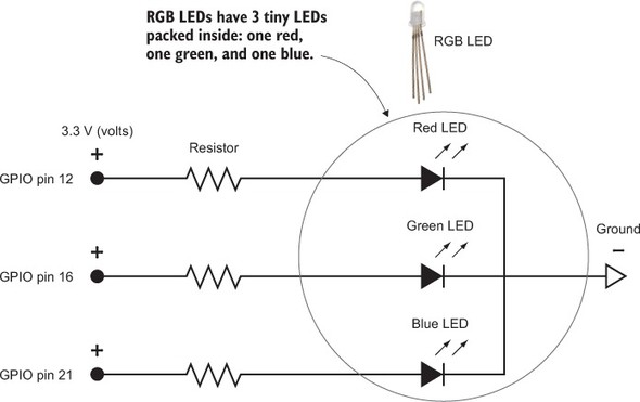
The circuit diagram for the Light Up Guessing Game is shown in Figure 7.4. To light the RGB LED, you’ll have electricity (+3.3 V) flow from your Pi’s GPIO pins 12, 16, and 21; through each resistor; through the LED; and then to ground (0 V).
Figure 7.4. Circuit diagram for the Light Up Guessing Game project
You’ll build the RGB LED circuit on the breadboard and then program it to light up. Wire it up in this order:
1. Put the RGB LED into the breadboard.
2. Connect the three jumper wires, which will connect the GPIO pins to the LED (one for each color).
3. Add the three resistors to connect the jumpers to the LED’s red, green, and blue legs.
4. Add the final jumper wire to connect the ground leg of the LED to the negative (ground) power bus.
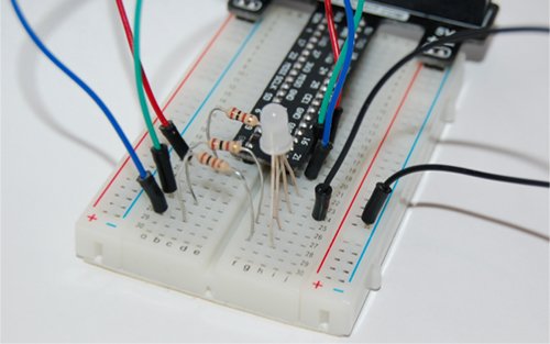
When it’s done, the circuit will look like what you see in figure 7.5. Let’s walk through the steps to build this circuit.
Figure 7.5. The RGB LED circuit you’re building on the breadboard uses GPIO pins 12, 16, and 21 to power the LEDs. The light won’t turn on until you program the voltage to come out of the pins.
Step 1. Add the RGB LED
Before you can add it to the breadboard, let’s look a bit closer at the RGB LED. Remember that there are three tiny LEDs (red, green, and blue) inside it. You need to be able to figure out which leg is which color and which one is ground. Figure 7.6 is a handy reference.
Figure 7.6. The RGB LED has lots of legs! The longest leg is the ground. The other ones are for red, green, and blue. This applies to what is called a common cathode RGB LED, which is what comes in Pi kits and what you’ll find most commonly at electronics suppliers.

Note
You’ll need to bend the RGB LED’s legs quite a bit to get them into the holes on the breadboard. Try to bend them to line up with the holes, and slowly push the legs in all at once.
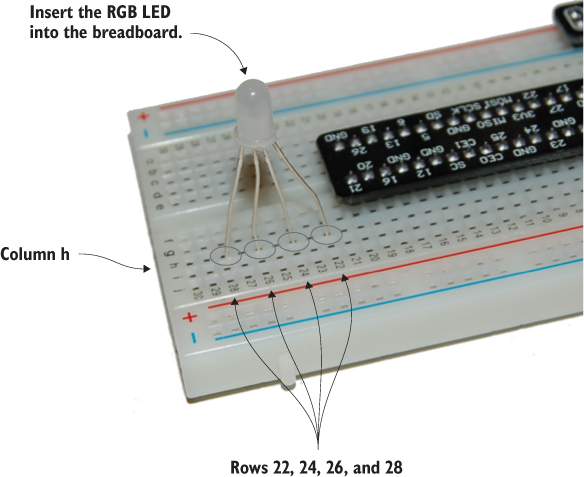
Grab your RGB LED, and let’s insert it into the breadboard. You’re going to put it in rows 22, 24, 26, and 28 along column h on the breadboard. Here’s where to connect the legs:
- Red leg into hole BB22h
- Ground leg (longest leg) into hole BB24h
- Green leg into hole BB26h
- Blue leg (shortest) into hole BB28h
When it’s inserted, it will look like Figure 7.7. Double-check that it’s pushed down into the breadboard so all the legs will make a good connection.
Figure 7.7. Bend the legs of the RGB LED, and insert it into the breadboard at BB22h, BB24h, BB26h, and BB28h. The longest leg goes into hole BB24h.
Good job! You just completed the trickiest part.
Step 2. Connect the GPIO jumper wires
The breakout board has numbers on it that refer to the Raspberry Pi’s GPIO numbering system. Remember that we refer to GPIO pins by adding GPIO before the number of the pin. So if we’re talking about GPIO pin 12, it’s GPIO12.
Question: What hole on your breadboard is next to GPIO12 (GPIO pin 12)?
Answer: Look closely, and you’ll see that the holes next to it are BB16i and BB16j.
Note
The color of the jumper wires doesn’t matter, but it’s sometimes helpful to pick ones that match the colors of the LED legs. When you’re troubleshooting problems, that can help you easily remember which GPIO pin is controlling each color of light coming out of the RGB LED.
Now that you’ve located the holes near the GPIO pins, you can start connecting jumper wires as follows:
- Jumper wire from BB16j to BB22a (connects GP12 to the red leg of the RGB LED)
- Jumper wire from BB18j to BB26a (connects GP16 to the green leg of the RGB LED)
- Jumper wire from BB20j to BB28a (connects GP21 to the blue leg of the RGB LED)
When you’ve added the wires, the circuit will look like figure 7.8.
Figure 7.8. The jumpers connect the GPIO pins from your Pi to the RGB LED. If you have an earlier model Pi, you can use other GPIO pins. Just remember which ones you’re using, and use these numbers when you program the Pi to turn the GPIO pins on and off.

Step 3. Add the three resistors
It’s time to connect your 180 ohm resistors![1] They should have bands of brown, grey, and brown, followed by a fourth gold or silver band. Remember that electricity will flow either way through a resistor, so the way you connect it doesn’t matter. Figure 7.9 is a handy diagram that reminds you how you can figure out the value of a resistor by using the colored bands.
This is a safe value that won’t risk damage to your Pi and will keep things simple. For those of you who are into precision, technically you might want to use slightly different resistors for each color LED (red, green, and blue), because each one requires a different amount of electrical current (amps) to make it shine. Check out some of the online resistor calculators and Pi forums on RGB LEDs if you’re interested.
Figure 7.9. The colored bands on a resistor tell you how much resistance the resistor has. For this project, you want a brown (1), grey (8), brown (×10) resistor, or 18 × 10 = 180 ohm resistor. Don’t have one? Any resistor between about 100 and 300 ohms should work well.

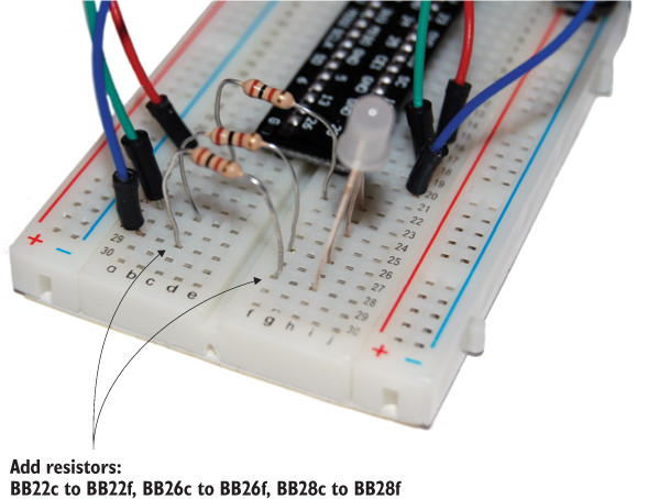
Connect the resistors as follows:
- Insert one end of the first resistor into BB22c and the other end into BB22f.
- Insert one end of the second resistor into BB26c and the other end into BB26f.
- Insert one end of the third resistor into BB28c and the other end into BB28f.
Once they’re added, you’ll have something that looks like figure 7.10. Now you’re ready for the final step!
Figure 7.10. Add your resistors! Make sure you push them down into the breadboard holes. If you don’t like them sticking up so high, you can trim the ends using wire cutters.
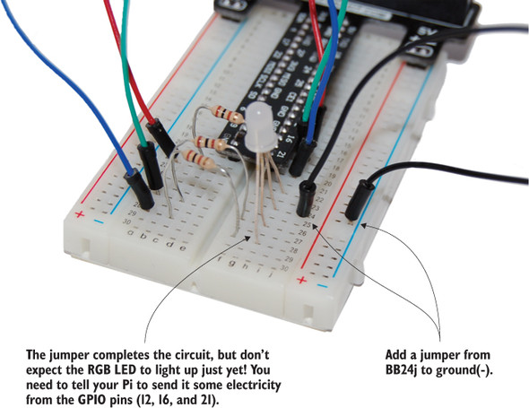
Step 4. Add the jumper to ground
Remember that a ground rail runs vertically along the right side of the breadboard, with a blue stripe next to it. Add a jumper from BB24j to the negative (-) power bus or ground rail (any hole next to the blue stripe will do). Figure 7.11 shows how it looks.
Figure 7.11. The jumper is added to connect the ground of the RGB LED to the ground of the Raspberry Pi. The jumper can connect anywhere along the ground rail (it usually has a blue stripe running next to it).
Wahoo! You’ve completed the RGB circuit on the breadboard. With the circuit complete, it’s time to write your program so you can test it.
You can program your RGB LED to light up red, green, or blue by turning on or off GPIO pins 12, 16, and 21. But RGB LEDs can make more colors by mixing different amounts of red, green, and blue light. For example, you can combine equal amounts of red and blue light to make a nice magenta color. Or to make your LED yellow, you can combine equal amounts of green and red. Televisions work on the same principle. This concept, called additive color, means mixing varying amounts of different colors of light to make new colors.

Wait! Your Pi can only turn LEDs on or off (you set them to HIGH or LOW)! How can you make something like a raspberry red color that might be 80% red and 20% blue? It’s possible, but you’ll need to learn how to very quickly pulse your Pi’s GPIO output. This is called pulse width modulation (PWM). Check online for information on how you can use the RPi.GPIO module to do PWM and create almost any shade of color you want.
Software: LEDGuessingGame program
You’re creating a game to guess a magic number. As mentioned at the start of the chapter, you’ll design the game play based on these simple rules (feel free to change them to your liking):
- The magic number is a randomly generated number between 1 and 20.
- The player is given five tries to guess the number correctly.
- If they guess correctly, the RGB LED flashes green.
- If they guess too high, the RGB LED flashes red.
- If they guess too low, the RGB LED flashes blue.
- After five guesses, the game is over.
- The player is given the choice to play again.
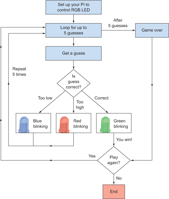
As you’ve seen in earlier chapters, programming is often about breaking down complex problems into smaller ones and then solving them. Let’s start by laying out a quick diagram outlining what the program should do (see figure 7.12).
Figure 7.12. Flow diagram showing how the guessing game should work. Notice how you’re blinking LEDs if the guess is too low, too high, or correct. You also give the player the choice of whether they’d like to play again.
As you approach this program, let’s see if you can simplify the code by organizing it into functions, especially when you have chunks of code that can be easily separated. Remember that you can use functions to organize your code and simplify it. You’ll create three functions to handle each of the flashing lights, to simplify the main part of your program:
- flash_red —Flashes the RGB LED red
- flash_blue —Flashes the RGB LED blue
- flash_green —Flashes the RGB LED green
You’ll also create a function to display a message when the game is over.
Now that you have a plan, let’s code it in this order:
1. Import libraries, create the flashing and game-over functions, and set up the GPIO pins for RGB LED output.
2. Display the title and introduction, create a loop, and get and check up to five guesses.
3. Add logic to allow the user to decide if they want to play again.
Let’s begin! Open IDLE by choosing Python 3 under Menu > Programming. This opens IDLE to the Python 3.x Shell. In the Python Shell, start a new program by pressing Ctrl-N or selecting File > New Window.
Setting up the GPIO pins for the RGB LED
In the IDLE 3 text editor, you’ll first load the Python libraries you need, create functions, and prepare your Pi to send electricity to the RGB LED (see figure 7.13).
Figure 7.13. The program starts by importing the Python libraries you’ll need to use, setting up your Pi’s GPIO pins for lighting up the LEDs, and defining the functions you’ll need.

Setting up your Pi’s GPIO pins
You need to get your Pi ready for output to the GPIO pins and tell the Pi which pins you plan to use (see listing 7.1). If you recall from the earlier wiring, you’re using these pins to control the three LEDs that are inside the RGB LED:
- GP12 for the red LED
- GP16 for the green LED
- GP21 for the blue LED
Later, you’ll write the code to control those pins. Let’s start by importing the GPIO library for the Raspberry Pi and setting up the GPIO pins so they can output a voltage to control the RGB LED.
Listing 7.1. Setting up the Pi’s GPIO pins


Great! You’ve started by importing the time and random libraries, because you’ll need them to flash the LED and help you generate a random number when the game starts. You define variables for the pins you’re using and even add a variable, BlinkTime, that says how much time you’ll blink the light on and off. Finally, you tell your Pi that you want to use three pins as output. Now let’s write the functions.
Creating functions to simplify the code
You need three functions to flash the three LEDs inside the RGB LED and one for game over. Name the flashing functions flash_red, flash_blue, and flash_green, as shown in the following listing.
Listing 7.2. Functions that flash LEDs different colors


In the code, you create four functions:
- flash_red()
- flash_green()
- flash_blue()
- game_over()
The three flashing functions blink a different color LED in the RGB LED. The blinking is created by using a for loop and the sleep function while you switch the output from the GPIO pin from HIGH (on) to LOW (off). Think of this as being like standing at a light switch and flipping it on and then off, five times.
Before you go any farther, save the program as LEDGuessingGame.py in your home folder.
Believe it or not, we don’t always know when to create a function. The ability to figure that out is a skill that comes with experience in writing programs and seeing patterns. Here are some tips for deciding what to make a function:
- Is there a group of instructions that you’ll need to use over and over again, with little variation?
- Do you have large blocks of code that make your programs hard to read?
Functions can simplify your code and make it easier to update.
Refactoring your functions
Did you notice that the functions for flashing the LEDs are very similar? Most of the code in each function is the same except for the GPIO pin, so let’s see if you can improve this code to make it simpler. This process of simplifying code is called refactoring.
What if you rewrote the three functions as a single function, as shown in listing 7.3? This new function takes one parameter, LED_pin, that represents the number of the GPIO pin you want to control. It can be any one of the GPIO pins you’re using for the colors of the RGB LED. For example, if LED_pin is 16, this corresponds to GPIO pin 16, which should blink the green light.
Listing 7.3. Refactoring the three flashing functions to a single function

In this case, you’re refactoring a set of functions that are very similar to a single function that takes a parameter (LED_pin). This parameter makes the function more flexible or dynamic so it can take the place of the three separate functions.
Main game loop and logic
The next part of the program creates the main game loop (see figure 7.14). You’ll do the following:
- Set up the game.
- Display the title and instructions for the person playing.
- Create some variables, and get a random number.
- Create the loop and guessing logic.
Figure 7.14. After displaying the game title and instructions, you need to define variables to store important game information, including a random number the player is trying to guess. The main loop in the game is repeated to allow the user to make five guesses; it also blinks the lights.

Game setup
Let’s look at some of the variables you’ll need for the game:
- number_in_my_head holds a random number (an integer between 1 and 20) that the player is trying to guess.
- count_guesses helps you count and keep track of how many guesses the player has made.
- play_again tracks the status of whether the player wants to play again. You’ll use a Boolean type for this, because it should always be True (yes, let’s play again) or False (no, let’s not play again).
The next listing adds these three variables and sets them up. You also create and display the title and game instructions.
Listing 7.4. Creating variables and displaying the game title and instructions
# A random number for our game
number_in_my_head = random.randint(1,20)
count_guesses = 1  # Counter for the number of guesses

# Used to keep track of whether they want to play again
play_again = True

title = """
**********************************************************************
                         Light Up Guessing Game
**********************************************************************
"""
print(title)

intro = """
Game Play:
I'm thinking of a number between 1 and 20. You have five guesses to guess it.
After each guess, my light will blink.

  Red ---> Your guess is too high!
  Green ---> Your guess is correct!
  Blue --> Your guess is too low
"""
Fantastic! The variables set the stage for the guessing-game logic. It’s a lot like the foundation of a house—you need it in order to build the rest.
Guessing Game Loop and logic
The code features two loops, one inside the other. The outer loop gives the user the option of playing again—we’ll call this the Play Again Loop. Within that loop is another that gives the player five guesses—we’ll call this the Guessing Game Loop.
The main game loop involves getting a guess, checking the guess, blinking the RGB LED the appropriate color, and then repeating until the player guesses right or has used all five guesses. The next listing shows the program for the Guessing Game Loop and the logic for checking guesses.
Listing 7.5. Guessing Game Loop

The Guessing Game Loop contains the logic to
- Keep track of the number of guesses.
- Get a guess.
- Check to see if a guess is correct, too high, or too low.
Where is the logic for responding to the player? It’s in the loop. Each time you get a guess, a series of if/elif statements checks whether the guess is correct, too high, or too low. Based on which of those cases is True, the flash() function is called to flash the appropriately colored LED on and off. If the user guesses the number correctly, the RGB LED will flash green, and then the break command will exit the while loop.
Notice that you add an else statement to the while loop. When the number of guesses has been exceeded (count_guesses is greater than 5), the else statement is triggered and the game_over function is called. The else block only happens when the while condition is checked and is False (in this case, when the number of guesses has exceeded 5).
In the next section, you’ll see how to give the player the option of playing again.
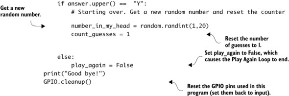
Adding the Play Again Loop and logic
You want to add a feature to the game that lets the user choose whether they want to play again. To do this, you need another loop that goes around the Guessing Game Loop (see figure 7.15). The Play Again Loop needs to repeat the Guessing Game Loop as long as the user answers that they want to play again.
Figure 7.15. The Play Again Loop is wrapped around the Guessing Game Loop. After the player has exhausted their guesses or guessed the number correctly, they’re asked if they want to play again. Depending on their answer, the game will either start over or end.

Listing 7.6. Play Again Loop

Awesome job! You have put together a circuit to control an RGB LED and written the Python code to make a game interact with it. Now, let’s test it.
Playing the game
Save the code as LEDGuessingGame.py, and try running it. Select Run > Run Module (or press F5) from the IDLE text editor to run your program. If you have an older version of Raspbian (prior to October 2015), open Terminal and enter the following command:
pi@raspberrypi ~ $ sudo python3 LEDGuessingGame.py
Excellent! You should see your guessing game start up. Let’s test it to see if it works. Try seeing if you can guess the number. Try getting it wrong, just to make sure the game_over function works.
Note
Remember that any programs that use GPIO pins must be run from the Raspbian command prompt as the superuser (or root). The sudo command lets you do this. If you try running the program at the Python Shell in IDLE, then you’ll get the error that ends “RuntimeError: No access to /dev/mem. Try running as root!”
Troubleshooting
If the lights aren’t blinking after each guess is made, here are some things you can check:
- Check the circuit on the breadboard. Is the ribbon cable connected properly, with the first wire connected toward the edge of the Pi, away from the USB ports?
- Double-check that the jumper, RGB LED, and resistors are connected to the correct holes on the breadboard. Could your RGB LED be inserted the wrong way (the shorter legs go toward the negative or ground side)? Try turning it around if you aren’t sure.
- Look through your Python program for errors. If necessary, edit the program to add some print statements so you can see which parts are working. For example, in the inner loop that handles the five guesses, you can
use the print function to display the value of count_guesses:
print(count_guesses)
- Try adding a print message in the flash function so you’re sure it’s being called. For example, you could add
print("Blinking the LED")
If you’ve enjoyed playing your game, try some additional challenges to increase the fun factor!
![]()
Challenges
These challenges use the RGB LED that you’ve already wired up. If you can’t figure them out, check appendix C for hints and solutions.
Game winner
Write a function in the game that creates a flashing animation whenever the user correctly guesses the number. For example, you could try quickly flashing the RGB LED different colors.
Easter egg
Was the last one too easy? Well, try this: create an Easter egg in your game. Create logic so that if someone types in a certain word (maybe Spam), the program displays a secret message and flashes the light in a crazy way.
Warmer and colder
Expand the logic of your program to make the speed of the blinking indicate whether the player’s guess is close to or far away from the correct answer. As a hint, think about the blinking speed you’ve set. Let’s say a guess is off by 10 (the player guesses 15, and the magic number is 5). You want the light to blink slowly. You can take the difference (ignore any negative signs) and divide it by 10. This will make the blinking speed one-tenth of the difference, or once every second if you’re off by 10 (pretty slow). If the player’s guess is off by 2, the light will blink every two-tenths of a second (pretty fast). This way, the blinking speed tells the player if their guess is close or far away.
Darth Vader surprise
Let’s see if you can get an image of Darth Vader to pop up if the player doesn’t correctly guess the number. Here’s a hint to get you started. Install the Linux image-viewing software called fim,[2] a program that allows you to open images from the Raspbian command line. To install fim, make sure your Pi is connected to the internet, and then open Terminal and use the following command:
fim is the improved version of fbi, image-viewing software for Linux that can be run from the command line.
pi@raspberrypi ~ $ sudo apt-get -y install fim
Next, download an image of Darth Vader and have the game display it on the screen. Let’s say you’ve downloaded an image called Darth_Vader.jpg. You can display it with these commands in Python:
import os
os.system("fim Darth_Vader.jpg")
Good luck! May the Force be with you!
Summary
In this chapter, you learned that
- Pis can respond in rich and exciting ways by interacting through the GPIO pins in your programs.
- Functions, loops, and conditional statements can be combined with your Pi’s output capabilities to create programs that react to people and the environment.
- RGB LEDs are very cool because they can make different colors and are actually three LEDs packed into one small package.
- A while loop can have an else statement that allows you to control what happens when the loop condition is no longer true.
- A play again loop can be wrapped around a main game loop to allow users to play the game over and over again.
- Refactoring is a fancy word that just means simplifying or shortening your code by looking for ways to make it more efficient. Be careful, though—you don’t want to simplify something so much that it becomes too hard to understand (remember the Zen of Python)!