
CHAPTER 1

The Art of Programming Mechanics
Everyone can be taught to sculpt: Michelangelo would have had to be taught how not to. So it is with the great programmers.
Alan Perlis
1.1 Introduction
In 1979, art teacher Betty Edwards published the acclaimed Drawing on the Right Side of the Brain. The essence of the text taught readers to draw what they saw rather than what they thought they saw. The human brain is so adept at tasks such as pattern recognition that we internally symbolize practically everything we see and regurgitate these patterns when asked to draw them on paper. Children do this very well. The simplicity in children's drawing stems from their internal representation for an object. Ask them to draw a house and a dog and you'll get something you and they can recognize as a house and dog or, more accurately, the icon for a house and
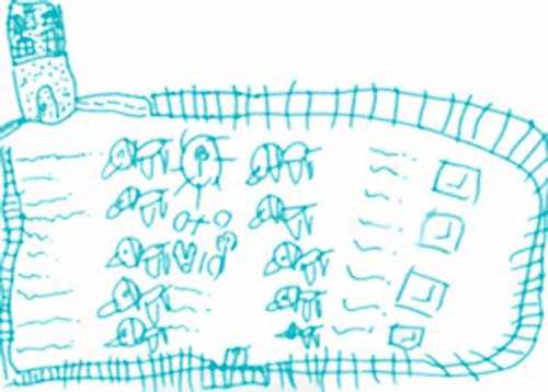
FIG 1.1 Dogs in the yard of a castle by Tabytha de Byl aged 4.
dog, but something far from what an actual house and dog look like. This is evident in the child's drawing in Figure 1.1. The title of the book, Drawing on the Right Side of the Brain, also suggests that the ability to draw should be summoned from the side of the brain traditionally associated with creativity and that most bad drawings could be blamed on the left.
Different intellectual capability is commonly attributed to either the left or the right hemispheres. The left side being responsible for the processing of language, mathematics, numbers, logic, and other such computational activities, whereas the right deals with shapes, patterns, spatial acuity, images, dreaming, and creative pursuits. From these beliefs, those who are adept at computer programming are classified as left-brained and artists as right-brained. The segregation of these abilities to either side of the brain is called lateralization. While lateralization has been generally accepted and even used to classify and separate students into learning style groups, it is a common misconception that intellectual functioning can be separated so clearly.
In fact, the clearly defined left and right brain functions are a neuromyth stemming from the overgeneralization and literal isolation of the brain hemispheres. While some functions tend to reside more in one side of the brain than the other, many tasks, to some degree, require both sides. For example, many numerical computation and language activities require both hemispheres. Furthermore, the side of the brain being utilized for specific tasks can vary among people. Studies have revealed that 97% of right-handed people use their left hemisphere for language and speech processing and 70% of left-handed people use their right hemisphere.
In short, simply classifying programmers as left brainers and artists as right brainers is a misnomer. This also leads to the disturbing misconception that programmers are poor at art skills and that artists would have difficulty understanding programming. Programming is so often generalized as a logical process and art as a creative process that some find it inconceivable that programmers could be effective as artists and vice versa.
When Betty Edwards suggests that people should use their right brain for drawing it is in concept, not physiology. The location of the neurons the reader is being asked to use to find their creative self is not relevant. What is important is that Dr. Edwards is asking us to see drawing in a different light—in a way we may not have considered before. Instead of drawing our internalized symbol of an object that has been stored away in the brain, she asks us to draw what we see. To forget what we think it looks like. In the end this symbolizes a switch in thinking away from logic and patterns to images and visual processing.
There is no doubt that some people are naturally better at programming and others at art. However, by taking Edwards' anyone can draw attitude, we can also say anyone can program. It just requires a little practice and a change of attitude.
1.2 Programming on the Right Side of the Brain
While it is true that pure logic is at the very heart of all computer programs, it still requires an enormous amount of creativity to order the logic into a program. The process is improved greatly when programmers can visualize the results of their code before it even runs. You may liken this to a scene from The Matrix where the characters look at screens of vertically flowing green numbers and text but can visualize the structure and goings on in a photorealistic, three-dimensional virtual reality. To become a good computer programmer you need to know the language of the code and be able to visualize how it is affecting the computer's memory and the results of running the program.
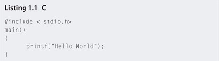
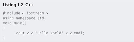
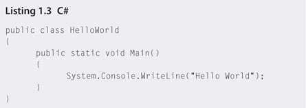
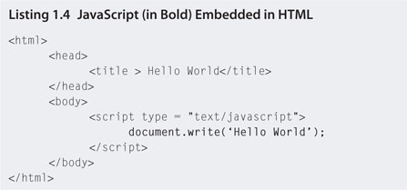
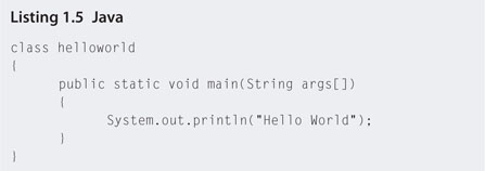
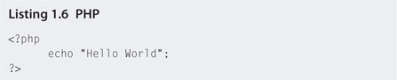
Learning a computer language is one key to being able to program. However, understanding how the language interacts with the computer to produce its output is even more important. Good programmers will agree that it is easy to switch between programming languages once you have mastered one. The fundamental concepts in each are the same. In some languages, such as C, C++, C#, Javascript, Java, and PhP, even the text and layout look the same. The basic code from each aforementioned language to print Hello World on the computer screen is shown in listings 1.1 through 1.6.
Umberto Eco, the creator of Opera Aperta, described the concept of art as mechanical relationships between features that can be reorganized to make a series of distinct works. This too is true of programming. The same lines of programming code can be reorganized to create many different programs. Nowhere is this shared art/programming characteristic more obvious than in fractals.
Fractals are shapes made up of smaller self-similar copies of themselves. The famous Mandelbrot set or Snowman is shown in Figure 1.2. The whole shape is made up of smaller versions of itself. As you look closer you will be able to spot tens or even hundreds of smaller snowman shapes within the larger image.
A fractal is constructed from a mathematical algorithm repeated over and over where the output is interpreted as a point and color on the computer screen. The Mandelbrot set comes from complex equations, but not all fractal algorithms require high-level mathematical knowledge to understand.
The Barnsley fern leaf is the epitome of both the creative side of programming and algorithmic nature of art. Put simply, the algorithm takes a shape, any shape, and transforms it four times, as shown in Figure 1.3. It then takes the resulting shape and puts it through the same set of transformations. This can be repeated infinitum; however, around 10 iterations of this process give a good impression of the resulting image (see Figure 1.4).
Creating images with these types of algorithmic approaches is called procedural or dynamic generation. It is a common method for creating assets such as terrain, trees, and special effects in games. Although procedural generation can create game landscapes and other assets before a player starts playing, procedural generation comes into its own while the game is being played.
FIG 1.2 The Mandelbrot set and periodicities of orbits.
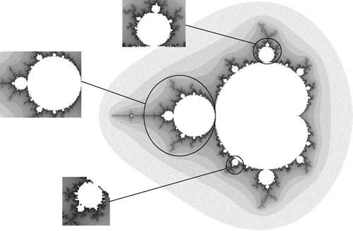
FIG 1.3 Transformations of Barnsley's fern leaf.
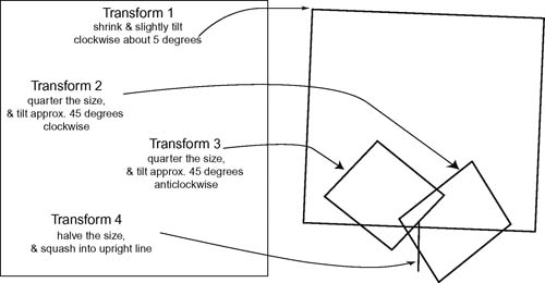
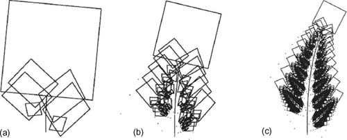
FIG 1.4 Three iterations of Barnsley's fern leaf transformations after (a) 2 iterations, (b) 5 iterations, and (c) 10 iterations.
Programming code can access the assets in a game during run time. It can manipulate an asset based on player input. For example, placing a large hole in a wall after the player has blown it up is achieved with programming code. This can only be calculated at the time the player interacts with the game, as beforehand a programmer would have no idea where the player would be standing or in what direction he would shoot. The game Fracture by Day 1 Studios features dynamic ground terrains that lift up beneath objects when shot with a special weapon.
![]() For Research
For Research
Procedural Generation in Unity
The Unity Web site has a project with numerous procedural generation demonstrations. At this point in your game development learning journey, you may not be able to understand the underlying code, but the examples will show you what is possible and the types of things you will be able to achieve by the end of this book. The Unity project can be downloaded from http://unity3D.com/support/resources/files/Procedural.zip.
A purpose-built programming language for creating art is Processing. The syntax of the code is not unlike JavaScript and contains all the fundamental programming concepts you will learn about in Section 1.4. The image in Figure 1.5 was created with Processing by randomly plotting circles and drawing a series of curves from a central location to each circle. Art created by Casey Reas, shown in Figure 1.6, created with Processing has been displayed at Gallery [DAM] Berlin.
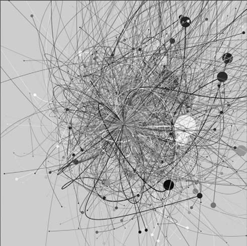
FIG 1.5 An image created with Processing.

FIG 1.6 Artwork created by Casey Reas using Processing as exhibited at Gallery [DAM] Berlin.
Getting Started with Processing
If you're interested in learning more about Processing and drawing images with programming code, you can download the open source language and find tutorials at http://processing.org
1.3 Creating Art from the Left Side of the Brain
Most people know what they like and don't like when they see art. However, if you ask them why they like it they may not be able to put their thoughts into words. No doubt there are some people who are naturally gifted with the ability to draw and sculpt and some who are not. For the artistically challenged, however, hope is not lost. This is certainly Betty Edwards' stance.
A logical approach to the elements and principles of design reveals rules one can apply to create more appealing artwork. They are the mechanical relationships, alluded to by Umberto Eco, that can be used as building blocks to create works of art. These fundamentals are common threads found to run through all good artwork. They will not assist you in being creative and coming up with original art, but they will help in presentation and visual attractiveness.
The elements of design are the primary items that make up drawings, models, paintings, and design. They are point, line, shape, direction, size, texture, color, and hue. All visual artworks include one or more of these elements.
In the graphics of computer games, each of these elements is as important to the visual aspect of game assets as they are in drawings, painting, and sculptures. However, as each is being stored in computer memory and processed by mathematical algorithms, their treatment by the game artist differs.
1.3.1 Point
All visual elements begin with a point. In drawing, it is the first mark put on paper. Because of the physical makeup of computer screens, it is also the fundamental building block of all digital images. Each point on an electronic screen is called a pixel. The number of pixels visible on a display is referred to as the resolution. For example, a resolution of 1024 x 768 is 1024 pixels wide and 768 pixels high.
Each pixel is referenced by its x and y Cartesian coordinates. Because pixels are discrete locations on a screen, these coordinates are always in whole numbers. The default coordinate system for a screen has the (0,0) pixel in the upper left-hand corner. A screen with 1024 x 768 resolution would have the (1023,767) pixel in the bottom right-hand corner. The highest value pixel has x and y values that are one minus the width and height, respectively, because the smallest pixel location is referenced as (0,0). It is also possible to change the default layout depending on the application being used such that the y values of the pixels are flipped with (0,0) being in the lower left-hand corner or even moved into the center of the screen.
1.3.2 Line
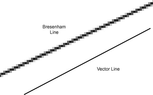
On paper, a line is created by the stroke of a pen or brush. It can also define the boundary where two shapes meet. A line on a digital display is created by coloring pixels on the screen between two pixel coordinates. Given the points at the ends of a line, an algorithm calculates the pixel values that must be colored in to create a straight line. This isn't as straightforward as it sounds because the pixels can only have whole number coordinate values. The Bresenham line algorithm was developed by Jack E. Bresenham in 1962 to effectively calculate the best pixels to color in to give the appearance of a line. Therefore, the line that appears on a digital display can only ever be an approximation to the real line as shown in Figure 1.7.
FIG 1.7 A real line and a Bresenham line.
1.3.3 Shape
A shape refers not only to primitive geometrics such as circles, squares, and triangles, but also to freeform and nonstandard formations. In computer graphics, polygons are treated as they are in geometry; a series of points called vertices connected by straight edges. By storing the coordinates of the vertices the edges can be reconstructed using straight line algorithms. A circle is often represented by as a regular polygon with many edges. As the number of edges increases, a regular polygon approaches the shape of a circle.
Freeform objects involve the use of curves. To be stored and manipulated by the computer efficiently, these need to be stored in a mathematical format. Two common types of curves used include Bezier and nonuniform rational basis spline (NURBS).
A Bezier curve is constructed from a number of control points. The first and last points specify the start and end of the curve and the other points act as attractors, drawing the line toward them and forming a curve, as shown in Figure 1.8. A NURBS curve is similar to a Bezier curve in that it has a number of control points; however, the control points can be weighted such that some may attract more than others.
In computer graphics, a polygon is the basic building block for objects, whether in 2D or 3D. A single polygon defines a flat surface onto which texture can be applied. The most efficient way to define a flat surface is through the use of three points; therefore, triangles are the polygon of choice for constructing models, although sometimes you will find square polygons used in some software packages. Fortunately for the artist, modeling software such as Autodesk's 3DS Studio Max and Blender do not require models to be handcrafted from triangles; instead they automatically construct any objects using triangles as a base as shown in Figure 1.9.
FIG 1.8 A Bezier and a NURBS curve.
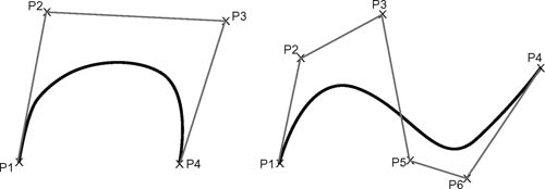
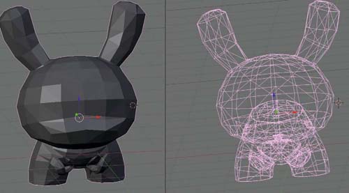
FIG 1.9 A 3D model constructed from triangles in Blender.
The wireframe model that represents a 3D object is called a mesh. The number of polygons in a mesh is called the polycount. The higher the polycount, the more triangles in the model and the more computer processing power required to render and manipulate the model. For this reason, computer game artists must find a balance between functionality and visual quality, as a high-resolution model is too costly with respect to making the game run slowly. The models must be dynamically processed and rendered in real time. In contrast, animated movie models can be much higher quality, as they are not rendered in real time. Next time you are playing a game, take a closer look at how the models are constructed.
1.3.4 Direction
Direction is the orientation of a line. Depending on its treatment, it can imply speed and motion. A line can sit horizontal, vertical, or oblique. In computer graphics, physics, engineering, and mathematics, a Euclidean vector is used to specify direction. A vector stores information about how to get from one point in space to another in a straight line. Not only does it represent a direction, but also a distance, otherwise called its magnitude. The magnitude of a vector is taken from its length. Two vectors can point in the same direction but have different magnitudes, as shown in Figure 1.10a. In addition, two vectors can have the same magnitude but different direction, as shown in Figure 1.10b. A vector with a magnitude of one is normalized.
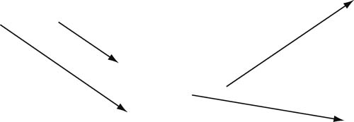
FIG 1.10 Vectors with the same direction but different magnitudes (a) and vectors with the same magnitude but different directions (b).
Vectors are a fundamental element in 3D games as they describe the direction in which objects are orientated, how they are moving, how they are scaled, and even how they are textured and lit. The basics of vectors are explored further in Chapter Two.
1.3.5 Size
Size is the relationship of the amount of space objects take up with respect to each other. In art and design it can be used to create balance, focal points, or emphasis. In computer graphics, size is referred to as scale. An object can be scaled uniformly or in any direction. Figure 1.11 shows a 3D object (a) scaled uniformly by 2 (b), by 3 vertically (c), by 0.5 horizontally (d), and by −1 vertically (e).
Note in Figure 1.11d how scaling by a negative value flips them vertically. They can also be achieved uniformly or horizontally using negative scaling values.
Depending on coordinates of an object, scaling will also move it. For example, if an object is centered around (0,0), it can be scaled remaining in the same place. However, if the object is away from (0,0), it will move by an amount proportional to the scale. This occurs as scaling values are multiplied with vertex coordinates to resize objects. A vertex at (0,0) multiplied by 2, for example, will remain at (0,0), whereas a vertex at (3,2) multiplied by 2 will move to (6,4). This is illustrated in Figure 1.12.
1.3.6 Texture
In art and design, texture relates to the surface quality of a shape or object. For example, the surface could be rough, smooth, or highly polished. In computer games, texture refers not only to the quality, but also to any photographs, colors, or patterns on the surface where the surface is defined by a polygon.
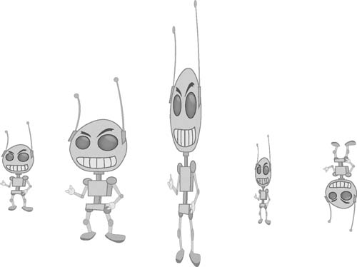
FIG 1.11 A 3D object scaled in multiple ways: (a) the original object, (b) scaled uniformly by 2, (c) scaled by 3 vertically, (d) scaled by 0.5 horizontally, and (e) scaled by −1 vertically.
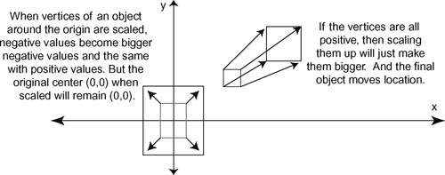
FIG 1.12 How scaling can move an object.
In games, textures are created using image files called maps. They are created in Adobe Photoshop or similar software. The image that gives an object its color is called a texture map, color map, or diffuse coloring. All images are mapped onto an object, polygon by polygon, using a technique called UV
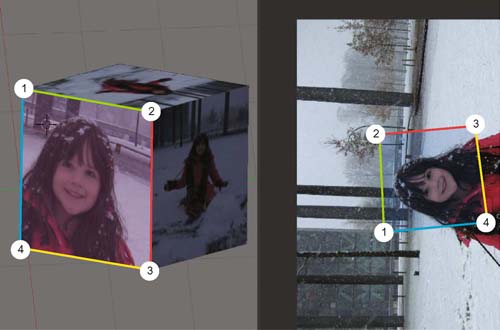
FIG 1.13 The UV mapping process. Vertices of a polygon on an object are mapped to locations on a 2D image.
mapping. This aligns points on an image with vertices of each polygon. The part of the image between the points is then stretched across the polygon. This process is shown on a square polygon in Figure 1.13.
To add a tactile look to the surface of a polygon enhancing the base texture, bump mapping is applied. This gives the object an appearance of having bumps, lumps, and grooves without the actual model itself being changed. Bump mapping is often applied to add more depth to an object with respect to the way light and shadow display on the surface. Figure 1.14 illustrates the application of a color and normal map on a soldier mesh taken from Unity.
A variety of other effects also add further texture to a surface. For example, specular lighting can make an object look glossy or dull, and shaders, small programs that manipulate the textures on a surface, can add a plethora of special effects from bubbling water to toon shading. A closer look at these will be included in later chapters.
1.3.7 Color
In the theory of visual art involving pigments, color is taught as a set of primary colors (red, yellow, and blue) from which all other colors can be created. The color perceived by the human eye is the result of light being
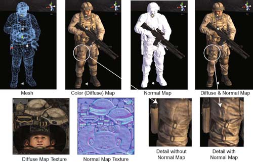
FIG 1.14 A soldier mesh with and without a color map and normal map.
reflected off the surface of the artwork. When all of the light is reflected, we see white. When none of the light is reflected, we see black. The resulting color of a mixture of primaries is caused by some of the light being absorbed by the pigment. This is called a subtractive color model, as the pigments subtract some of the original light source before reflecting the remainder.
The light from a digital display follows an additive color model. The display emits different colors by combining the primary sources of red, green, and blue light. For this reason, color is represented in computer graphics as a three or four numbered value in the format (red, green, blue, alpha). In some formats, the alpha value is not used, making color a three value representation.
Alpha represents the transparency of a color. When a surface has a color applied with an alpha of 0, it is fully transparent; when it has a value of 1 it is totally opaque. A value of 0.5 makes it partially transparent. Values for red, green, and blue also range between 0 and 1, where 0 indicates none of the color and 1 all of the color. Imagine the values indicate a dial for each colored lamp. When set to 0 the lamp is off and when set to 1 it is at full strength—any values in between give partial brightness. For example, a color value of (1,0,0,1) will give the color red. A color value of (1,1,0,1) will give the color yellow. The easy way to look up values for a color is to use the color picker included with most software including MS Word and Adobe Photoshop. The color picker from Adobe Photoshop is shown in Figure 1.15.
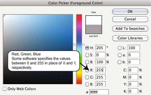
FIG 1.15 The Adobe Photoshop color picker.
An alternate way to set the value of a color is with values between 0 and 255 instead of between 0 and 1. It depends on the software you are using. In programming, values are usually between 0 and 1 and more commonly between 0 and 255 in color pickers.
Also included with most color pickers is the ability to set the color using different color models. The one shown in Figure 1.15 includes a Hue, Saturation, and Brightness model, as well as a CMYK model. For more information on these, check out http://en.wikipedia.org/wiki/Color_model.
1.4 How Game Engines Work
A game engine takes all the hard work out of creating a game. In the not so distant past, game developers had to write each game from scratch or modify older similar ones. Eventually game editor programs started to surface that allowed developers to create games without having to write a lot of the underlying code.
The game engine takes care of things such as physics, sound, graphics processing, and user input, allowing game developers to get on with the creation of high-level game mechanics. For example, in Unity, physical properties can be added to a ball with the click of a button to make it react to gravity and bounce off hard surfaces. Driving these behaviors, embedded in the engine, are millions of lines of complex code containing many mathematical functions related to real-world physics. The game developer can spend more time designing what the ball looks like and even selecting the type of material it is made from without having a background in Newtonian physics.
1.4.1 A Generic Game Engine
To understand how a game engine works, we will first look at a simple illustration of all its components. A conceptualization is shown in Figure 1.16.
The game engine is responsible for the running of a variety of components that manage all the game resources and behaviors. The Physics Manager handles how game objects interact with each other and the environments by simulating real-world physics. The Input Manager looks after interactions between the player and the game. It manages the drawing of graphical user interfaces and the handling of mouse clicks and the like. The Sound Manager is responsible for initializing and controlling how sound is delivered from the game to the player. If 3D sound is called for it will ensure that the right sound at the right volume is sent to the correct computer speaker.
FIG 1.16 Parts of a generic game engine.
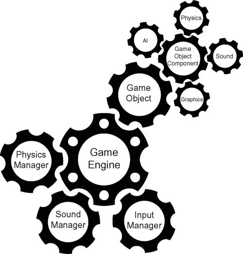
In addition to these managers are game objects. Game objects represent all the assets placed in a game environment. These include the terrain, sky, trees, weapons, rocks, nonplayer characters, rain, explosions, and so on. Because game objects represent a very diverse set of elements, they can also be customized through the addition of components that may include elements of Artificial Intelligence (AI), sound, graphics, and physics. The AI component determines how a game object will behave. For example, a rock in a scene would not have an AI component, but an enemy computer-controlled character would have AI to control how it attacks and pursues the player. A sound component gives a game object a sound. For example, an explosion would have a sound component whereas a tree may not. The physics component allows a game object to act within the physics system of the game. For example, physics added to a rock would see it roll down a hill or bounce and break apart when it falls. The graphics component dictates how the game object is drawn. This is the way in which it is presented to players on the screen. Some game objects will be visible and some will not. For example, a tree in a scene is a visible game object, whereas an autosave checkpoint, which may be a location in a game level, is not.
1.4.2 The Main Loop
All games run in the same way, as illustrated in Figure 1.17. There is an initialization stage in which computer memory is allocated, saved information is retrieved, and graphics and peripheral devices are checked. This is followed by the main game loop or main loop. The main loop runs continuously over and over again until the player decides to quit the game. While in the main loop the game executes a cycle of functions that processes user input messages; checks through all game objects and updates their state, including their position; updates the environment with respect to game object positions, user interaction, and the physics system; and finally renders the new scene to the screen.
Essentially each loop renders one frame of graphics on the screen. The faster the loop executes, the smoother the animation of the game appears. The more processing that needs to be performed during the main loop, the slower it will execute. As the number of game objects increases, the amount of work the main loop has to do also increases and therefore slows down the time between frames being rendered on the screen. This time is called frames per second (FPS).
Game developers strive for very high FPS, and for today's computers and consoles, FPS can extend beyond 600. In some circumstances, however, such as on mobile devices with less processing power, FPS can become very low with only several game objects, and the animation will flicker and user controls are nonresponsive. Having said this, beginner game developers need to be aware of this issue as even on a very powerful computer, adding a lot of highly detailed game objects can soon bring the FPS to a grinding halt. Anything below 25 FPS is considered unacceptable, and as it approaches 15 FPS the animation starts to flicker.
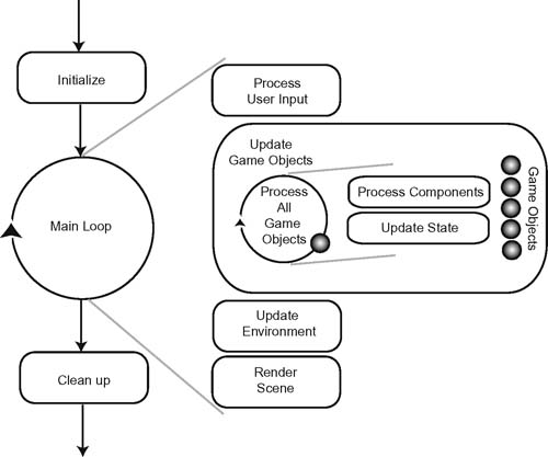
FIG 1.17 How a game runs.
Game Objects
Game objects are the fundamental building blocks for Unity games. It is through the addition, modification, and interaction of game objects that you will create your own game. After adding a game object in Unity (which you will do in the next section), a variety of components can be added to give the game object different functionalities. In all there are seven component categories. These are explored thoroughly throughout this book. In short, they are mesh, particles, physics, audio, rendering, miscellaneous, and scripts as shown in Figure 1.18. A game object can have all, none, or any combination of these components added. The game object exemplified in Figure 1.18 has at least one of each of these component types added.
A Mesh component handles the drawing of an object. Without a Mesh component, the game object is not visible. A Particles component allows for a game object to have a particle system added. For example, if the game object were a jet fighter, a particle system could be added to give the effect of afterburners. A Physics component gives the game object real-world physical properties so it can be collided with and affected by gravity and other physics effects. An Audio component adds sound or sound effects to a game object. For example, if the game object were a car, the noise of a car engine could be added. A Rendering component adds special effects to a game object such as emitting light. Miscellaneous components include a variety of effects for the game objects that do not fit within other categories. In Figure 1.18, the Wind Zone component is shown as a type of miscellaneous component. In brief, this causes the game object to become a source of wind for interaction within the physics system. Finally, Scripts are components that contain programming code to alter the behavior of a game object. Scripts can be used for a large variety of purposes and are fundamental to developing game mechanics and tying an entire game together.
In Unity, scripts added to game objects can be written in JavaScript or C#. This book uses JavaScript, as it requires less background knowledge in programming to get started and the syntax is more forgiving than C#.
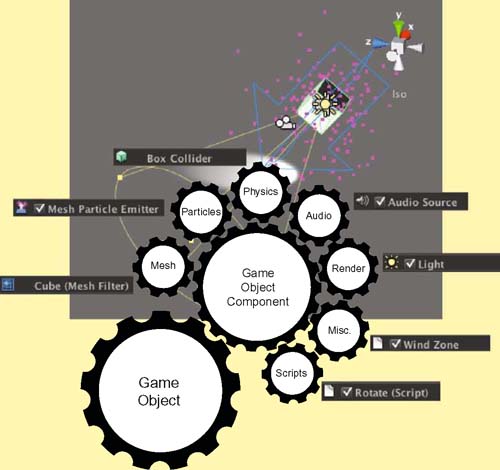
FIG 1.18 Components that can be added to a game object in Unity.
Getting to Know the Unity3D Development Environment
Step 1. To begin, download Unity by visiting http://unity3D.com/ and clicking on Download. Unity has a free version that lacks some functionality, but never expires. The free version is still quite powerful and is certainly enough for the first-time game developer. Once you have downloaded the software, follow the installation instructions to get Unity up and running.
Step 2. Running Unity for the first time reveals the multiwindowed editing environment shown in Figure 1.19. The tabs and windows can be dragged around to suit your own preferences.
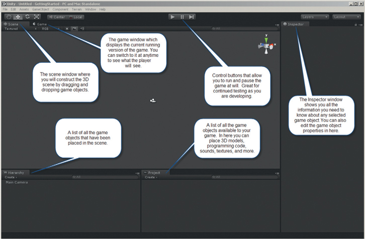
FIG 1.19 The Unity 3 editing environment.
![]() On the Web
On the Web
Navigating the Unity Editor Interface
Visit the Web site for a short video demonstrating some best practices for finding your way around in the Unity Editor.
Step 3. After starting Unity, create a new project by selecting File > New Project. Note the project name and directory used to save the project are one and the same; by default, this is “New Unity Project.”
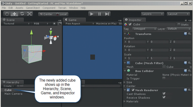
Step 4. To create a simple scene, select GameObject > Create Other > Cube from the main menu. All objects added to a game scene are called GameObjects in Unity. A cube will appear in the Hierarchy, Scene, Game, and Inspector windows.
![]() Note
Note
From this point in the text, these windows will be referenced just by their capitalized names.
Step 5. If the cube appears very small, place your mouse in the Scene and use the scroll wheel to zoom in. Note that your viewing position and angle in the Scene do not affect the look of the final game or change the attributes of any game objects. This initial Scene is shown in Figure 1.20. The Inspector shows all the properties of the cube. This includes its position, rotation, scale, the 3D mesh representing it, and a physics collider. We will look at these properties in more detail later.
FIG 1.20 A single cube in a scene.
Step 6. At this time, press the play button. As you have not added any functionality at this stage when running, all the game will do is display a static cube.
Unity allows you to edit your game as it is running. This is great if you want to test out an idea to see how the game will react. Be careful though because any changes you make in the editor, while play is on, will revert back to their previous value when you press stop. This can be very annoying if you've made large changes not realizing you are in play mode as they will be wiped away as soon as you press stop. The only exceptions to this are script files because they are edited and saved externally to the editor. Changes made in script files are independent of the play button.
Step 7. Although lighting is a subject usually delayed for more advanced topics in game development, the author always like to add a light to scenes to give them more depth and bring them alive. In the Scene, the cube is already shaded, as this is the default method of drawing. However, in the Game, the cube is a lifeless, flat, gray square. To add a light, select GameObject > Create Other > Directional Light from the main menu. A light displaying as a little sun symbol will appear in the Scene and the cube in the Game will become brighter.
Step 8. Now because we are looking at the cube front on in the Game, it still appears as a little square. Therefore, we need to transform it for viewing. A transformation modifies the properties of position, rotation, and scale of a GameObject. The specifics of transformation are discussed later, but for now you can transform the cube quickly using the W key for changing position, the E key for rotating the objects, and the R key for scaling it. Before pressing any of these keys, ensure that the cube is selected in the Hierarchy window. When it is selected, it will have a green and blue wireframe displayed on it.
Step 9. In W (position) mode, the cube will be overlaid with red, green, and blue arrows. These represent the x, y, and z axes of the object. Clicking and dragging from any of the arrowheads will move the object along that axis. To move the object freely, click and drag from the central yellow box.
Step 10. In E (rotate) mode, the cube will have red, green, and blue circles drawn around it. Click and drag any of these circles to rotate the cube in the associated directions.
Step 11. In R (scale) mode, the red, green, and blue axes will include small cubes on the ends. Clicking and dragging any of these will change the scale of the object in the respective directions. You may also click and drag the central small cube to resize the object in all directions uniformly. Note that while you are moving, rotating, and scaling the cube that it changes in the Game window accordingly. You will also notice that values in the Transform part of the Inspector change too. Move and scale the cube so that you can see it clearly in the Game window.
Step 12. The color of a GameObject comes from an associated material. To create a material, click on Create in the Project window and select Material. New material will appear in the Project window and, when selected, its properties in the Inspector are as shown in Figure 1.21.
FIG 1.21 Creating new material.
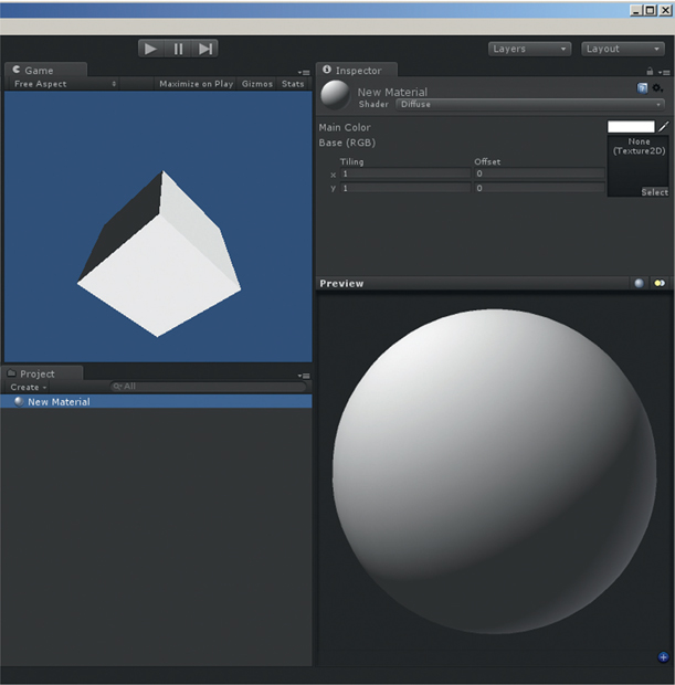
Step 13. To change the color of this material, click on the white box next to Main Color in the Inspector. Select the color you want from the Color Popup and then close it. The large sphere view of the material in the Inspector will change to your chosen color. To change the name of the material, click on New Material once in the Project window. Wait a moment and then click on it again slowly. This will place you in editing mode for the material name. Type in a new name and hit the Enter key.
Step 14. To add material to the cube, drag and drop your material from the Project window onto the cube in the Scene. Alternatively, you can drag and drop the material from the Project window and drop it onto the cube listed in the Hierarchy window. Both will achieve the same effect. The cube will be colored.
Step 15. In the Project window, select Create and then JavaScript. The JavaScript created will be called NewbehaviorScript. Change this, by slow clicking on it, as you did with the material, to spin.
![]() Note
Note
When you create a new JavaScript file, you only give it a name. Do not add .js on the end. Unity will do this for you automatically. However, in the Project, spin.js will only appear in the list as spin, without the .js on the end.
Step 16. Double-click on it and a code/text editor will open for entering code. In the code editor type:
function Update()
{
transform.Rotate(Vector3.up * 10);
}
The code must be EXACTLY as it appears here. Ensure that you have the correct spelling and capitalization, as otherwise it may not work. For large spaces, for example, before the word transform, insert a tab. When you are done, save your code in the text editor.
![]() Note
Note
The code in Step 15 contains the Unity function Update(). Whatever code you place inside Update() will be run once each main loop. Therefore, the code in Step 15 will run over and over again for the entire time the play button is down.
Step 17. Return to Unity and drag and drop the spin code from the Project window onto the cube in the Hierarchy window. You'll notice that if you select the cube, the spin script will appear as a component added to the cube in the Inspector as shown in Figure 1.22.
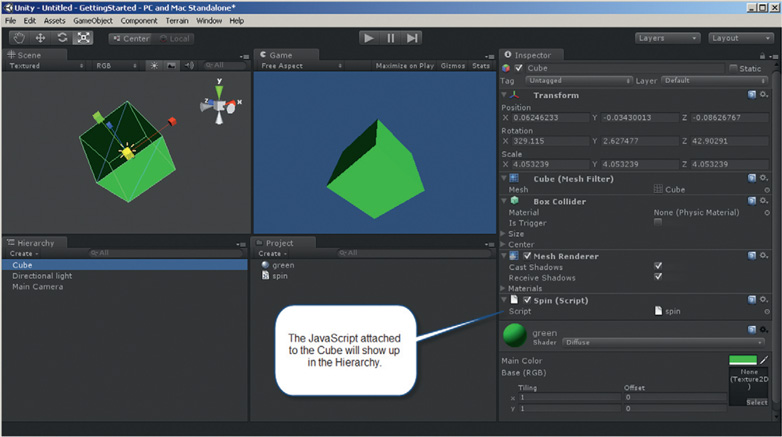
FIG 1.22 The cube with the spin script attached.
Step 18. Press the play button and watch as the cube spins.
Step 19. To save the application, select File> Save Scene from the main menu. In the dialog that pops up, give the scene a name such as spinningCube. Next, select File> Save Project from the main menu.
Each project you create can have multiple scenes. Scenes are saved inside projects. For example, an entire game application would be a single project. However, inside the game there would be multiple scenes, such as Main Menu, Help Screen, Map View, and 3D View. Single scenes can also be imported from one project to another.
1.5 A Scripting Primer
Hard-core programmers do not strictly consider scripting as programming, as it is a much simpler way of writing a program. Scripting languages have all the properties of programming languages; however, they tend to be less verbose and require less code to get the job done. For example, the JavaScript and Java shown in Listings 1.4 and 1.5, respectively, demonstrate how the scripting language JavaScript requires much less code to achieve the same outcome as Java. The major difference between programming and scripting is that programming languages are compiled (built into a program by the computer) and then run afterward and a scripting language is interpreted by another program as it runs. This book refers to the JavaScript you are about to learn as being compiled, when in reality at the technical level it isn't really.
When a program is compiled, it is turned into machine code the computer can understand. Compilation checks through the code for errors and then builds it into a program. Don't worry if you get lots of errors when you start programming. It is a normal part of the learning process. Some of the error messages will also seem quite vague and ambiguous for what they are trying to tell you. However, a quick search on Google will often reveal their true meaning.
JavaScript is used in this book as the primary means of programming. Although it is strictly a scripting language, it will be referred to in terms of programming, as it will be used to add computational functionality to games developed in Unity. Its syntax and constructs are also closely related to C++, C#, and Java; therefore, as a beginning language to learn it is ideal. It also provides a very powerful and yet simple way to develop game mechanics in Unity and many other game-editing environments.
Several fundamental constructs in programming are required to fully understand a programming language. These are variables, operations, arrays, conditions, loops, functions, and objects. However, the most fundamental and important concept that underlies everything is logic.
1.5.1 Logic
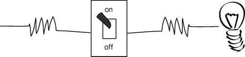
At the heart of all computers are the electronic switches on the circuit boards that cause them to operate. The fact that electricity has two states, on or off, is the underlying foundation on which programs are built. In simplistic terms, switches (otherwise known as relays) are openings that can either be opened or be closed, representing on and off, respectively. Imagine a basic circuit illustrated as a battery, electric cable, light switch, and lightbulb shown in Figure 1.23.
When the switch is open, the circuit is broken and the electricity is off. When the switch is closed, the circuit is complete and the electricity is on. This is exactly how computer circuitry works. Slightly more complex
FIG 1.23 A very basic electric circuit.
switches called logic gates allow for the circuit to be opened or closed, depending on two incoming electrical currents instead of the one from the previous example.
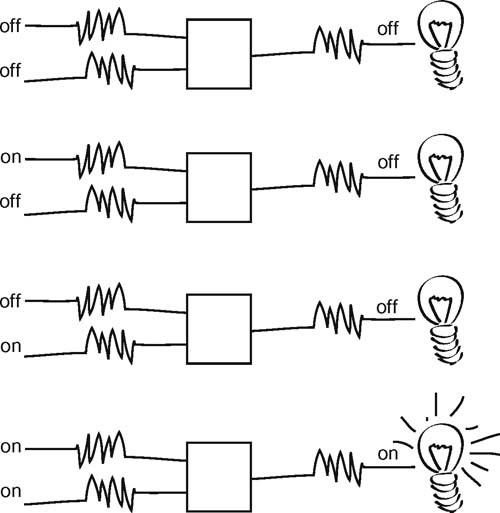
In all, there are seven logic gate configurations that take two currents as input and output a single current. These gates are called AND, OR, NOT, NAND, NOR, XOR, and XNOR. The AND gate takes two input currents; if both currents are on, the output current is on. If only one or none of the input currents is on, the output is off. This is illustrated in Figure 1.24.
In computer science,1 the operation of combining two currents or signals into one is called Boolean algebra2 and logic gate names (i.e., AND, OR) are called Boolean functions, although the on signal in computer science is referred to as TRUE or the value 1 and off is FALSE or 0. Using this terminology, all possible functions of the AND gate can be represented in truth tables shown in Table 1.1. It should be noted from Table 1.1 that truth tables can be written in a number of formats using 1s and 0s or TRUEs and FALSEs.
FIG 1.24 A conceptualization of an AND logic gate.
| Format 1 | Format 2 | ||||
| Input | Output | Input | Output | ||
| A | B | A and B | A | B | A and B |
| 1 | 1 | 1 | TRUE | TRUE | TRUE |
| 1 | 0 | 0 | TRUE | FALSE | FALSE |
| 0 | 1 | 0 | FALSE | TRUE | FALSE |
| FALSE | FALSE | FALSE | FALSE | FALSE | FALSE |
Each Boolean function has its own unique truth table. They work in the same way as the AND function does. They have two input values of TRUE and/or FALSE and output a value of TRUE or FALSE.
If you are just learning about programming for the first time right now, these concepts may seem a bit abstract and disconnected from real programming. However, as you learn more about programming, you'll realize how fundamental knowing these truth tables is to a holistic understanding. It will become much clearer as you begin to write your own programs.
![]() Quick Reference
Quick Reference
Boolean Algebra
| Function | Boolean algebra syntax | JavaScript | Truth table | |||
| AND | A · B | A && B | INPUT | OUTPUT | ||
| A | B | A AND B | ||||
| 0 | 0 | 0 | ||||
| 0 | 1 | 0 | ||||
| 1 | 0 | 0 | ||||
| 1 | 1 | 1 | ||||
| OR | A + B | A || B | INPUT | OUTPUT | ||
| A | B | A OR B | ||||
| 0 | 0 | 0 | ||||
| 0 | 1 | 1 | ||||
| 1 | 0 | 1 | ||||
| 1 | 1 | 1 | ||||
| NOT | A | !A | INPUT | OUTPUT | ||
| A | NOT A | |||||
| 0 | 1 | |||||
| 1 | 0 | |||||
| NAND | A·B | !(A && B) | INPUT | OUTPUT | ||
| A | B | A NAND B | ||||
| 0 | 0 | 0 | ||||
| 0 | 1 | 1 | ||||
| 1 | 0 | 1 | ||||
| 1 | 1 | 0 | ||||
| NOR | A+B | !(A || B) | INPUT | OUTPUT | ||
| A | B | A NOR B | ||||
| 0 | 0 | 1 | ||||
| 0 | 1 | 0 | ||||
| 1 | 0 | 0 | ||||
| 1 | 1 | 0 | ||||
| XOR | A ⊕ B | ( A && !B ) || ( !A && B ) | INPUT | OUTPUT | ||
| A | B | A XOR B | ||||
| 0 | 0 | 0 | ||||
| 0 | 1 | 1 | ||||
| 1 | 0 | 1 | ||||
| 1 | 1 | 0 | ||||
| XNOR | A |
(!A && !B) || (A && B) | INPUT | OUTPUT | ||
| A | B | A XNOR B | ||||
| 0 | 0 | 1 | ||||
| 0 | 1 | 0 | ||||
| 1 | 0 | 0 | ||||
| 1 | 1 | 1 | ||||
Interactive Boolean Algebra Logic Gates
Navigate to the book's Web site for an interactive Unity version of Boolean algebra.
1.5.2 Comments
Comments aren't actually programming code. They are, however, inserted lines of freeform text totally ignored by the compiler. They allow you to insert explanations about your code or little reminders to what your code does. They are very useful when you write some ground-breaking code, leave it for 6 months, and then come back to it, having forgotten what it does. The author's advice is to use comments as frequently as possible. It is common practice to place comments at the top of each program file to give an overview of the entire code, as well as above each function. Another programmer may also insert comments if he makes a change. Some examples are shown in Listing 1.7.
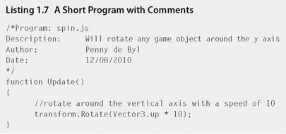
There are two types of comments. The first is a way to block out an entire paragraph. It begins with a /* and ends with a */. You can write anything you want between these characters and it will be totally ignored by the compiler. The second type is a one liner. A line starting with // will also be ignored by the compiler, but only until the end of the line. Therefore, you could write this:
/* Here are some comments about my program I wrote to control a spinning cube in Unity. I used the code I found in the Script Reference after doing a search for the word Rotate.*/
or this:
//Here are some comments about my program I wrote to control a
//spinning cube in Unity. I used the code I found in the
//Script Reference after doing a search for the word Rotate.
Use comments wisely and as you see fit. It is quite legitimate to write an entire program without comments; however, be warned, when you come back to code several months later you'll be glad you did.
1.5.3 Functions
A function is a block that bundles a number of lines of code together to form a specific operation. It contains prewritten code that can be reused over and over again, saving programmers the stress of reinventing the wheel each time they write a program. Programmers can also write their own functions.
Whenever the author thinks of functions, she visualizes them as food processing machines. You put vegetables in, they get processed, and you get chopped, mashed, or minced vegetables out.
The most common newbie function taught is print() or a derivative thereof. This function takes input and prints it to the screen. For example,
print(“Hello Unity”);
will print
Hello Unity
on the screen or console.
Functions available to you as a programmer will depend on the programming language. JavaScript has numerous standard functions but also takes on added ones depending on the context. For example, when JavaScript is embedded into the HTML of a webpage,
document.write(“Hello Unity”);
will display the text on the webpage when viewed inside a browser. To define your own function in JavaScript, the format is that shown in Listing 1.8.

A function declaration begins with the keyword function, followed by its name and then a list of input values.
While functions are a programming element usually introduced to new programmers further down the track, they are fundamental to writing JavaScript code for Unity and therefore are being explained up front.
Functions
Several essential JavaScript functions need to be included in your script to talk to Unity. As Unity is running your game, it will look through code attached to all game objects for functions it needs to execute at any particular time. For example, the Update() function runs once each main loop. If there are five game objects each with Update() functions in their scripts, then all five Update() functions will be executed.
Another useful function is Start(). This function runs just once during the lifetime of the game object. Think of it as an initialization method for a game object. You can use it to set initial states and values for a game object. It does not run over and over again like the Update() function and therefore is a good place to put code that does not need to run for the life of the game object. For example, if you want to constantly rotate an object like that in Listing 1.7, then it makes sense for the rotation to occur each loop. However, if you want to set the color of a game object to red, coding it in an Update() function will just cause the same command to run over and over again. Once the object is red, there is no need to keep setting it to red. A more suitable place to make an object red would be in the Start() function. It is set to red just once.
Remember, code inside Update() runs each main loop and each line of code in the main loop will cause it to run slower, albeit a minute amount, but superfluous code can soon add up to huge drops in frame rates.
![]() For Research
For Research
More Unity Functions
More Unity-specific functions will be revealed throughout the book as needed. If you are interested in other available functions, go to the Script Reference, type Monobehavior in the search, and have a look at the Overridable Functions. These are the ones you can use in your JavaScript.
1.5.4 Variables
A variable is the name of a piece of computer memory allocated for your program. Think of it as a storage box that you can put things into, take things out of, add to, and change. A variable in programming is similar to a variable in algebra that holds a numerical value. However, in programming, pretty much anything can be placed into a variable. In the line of code,
x = 50;
x is the name of the variable and it has a value of 50. If you continued with
y = x + 30;
another variable called y is being given the value of x (50) plus 30. The value of y in this case would be 80.
The differing types of information that can be stored in variables are called data types. These include integers (whole numbers, e.g., 5), floating point numbers (numbers with decimal values, e.g., 3.14), characters (a single alphanumeric value), strings (words and texts, e.g., “hello”), Boolean values (e.g., true and false), and other data types made from mixtures of the aforementioned.
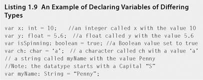
Variables don't just exist automatically in computer memory. They must be declared. The process of declaring a variable gives it a name, initial value, and a size. Some examples are shown in Listing 1.9.
If you don't know what value should be placed into a variable you do not need to assign one. For example,
var x: int;
will create an integer variable called x and the value will be set to 0 automatically.
Variables in computer memory can be conceptualized as boxes in a large storage space. The different types of variables have different sized boxes. The smallest box is a Boolean, as you only need to store a value of 1 or 0 inside it. A character is the next size up. It would hold all the alphanumeric characters such as those appearing on the keys of your keyboard and a couple of miscellaneous others. The integer size box is even bigger, holding numbers between −32,768 and 32,767 and a float box bigger again holding numbers with seven decimal digits of significance between 0.000000 x 10−95 and 9.999999 x 1096. The exact size of the boxes will change depending on operating system and computer processor,3 but the relative sizes remain the same. A conceptualization of memory allocation from variable declarations is shown in Figure 1.25.
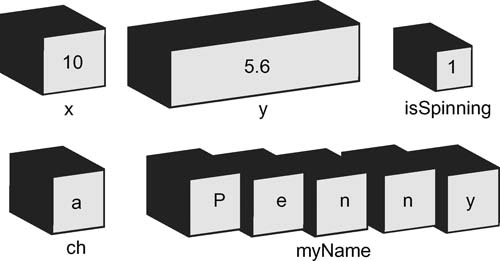
FIG 1.25 A conceptualization of the memory allocation, which occurs from Listing 1.9.
One thing to note from Listing 1.9 is the way characters and strings are given values. A single character is enclosed in single quotes and a string in double quotes. The reason being that if they were not, the compiler would consider them to be other variable names.
This brings us to another matter about naming variables. Variables can be named anything you like, keeping in mind the following. Variable names
- must start with a letter or number (e.g., myNumber, x, 7number, name10)
- cannot contain spaces (e.g., my Number)
- cannot be the same as a reserved word [these are the key words used in the programming language (e.g., var, for, function, transform)]
- cannot be the same as another variable unless it's in a different function (e.g., var x:int = 10; var x: char = ‘t’)
Also keep in mind that variable names can make your code more readable and can reduce the need for comments. For example,
x = 10;
is ambiguous, whereas
accountBalance = 10;
has more meaning.
You will notice the use of capital letters in some of the variable names shown beforehand. This is just one convention of using several words in the one name. The capital makes the variable name more readable as single words are easier to read. A variable name could also be written
account_Balance
using the underscore to separate words. This is a totally personal preference and makes no difference to the compiler; however, naming conventions4 are recommended. For example, if programming in JavaScript, camel casing for variable names is recommended with the first letter being in lowercase. Because conventions can vary slightly between languages, it will not be covered in this book.
JavaScript Variables
Variables in Unity JavaScript usually appear at the top of the code file. Although they could be placed in a variety of locations, the best place is at the top because they are easy to find. We will examine other types of variables in later sections.
Consider the script in Listing 1.10.
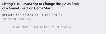
The line showing the variable declaration is shown in bold. Note, do not use bold in your own code; this is for illustrative purposes only. The keyword private forces the variable to remain hidden for use inside the JavaScript file in which it is declared. It cannot be seen for use by other code files. You can add many JavaScript files into the same Unity application, and sometimes you will want to be able to share the variable contents between these. In this case, you would declare an exposed variable. In this example, the code would be the same as Listing 1.10, except the private keyword would be removed.
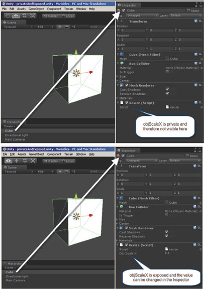
When a variable becomes exposed, it also appears in the Inspector of the Unity Editor where values can be entered manually. The difference is illustrated in Figure 1.26.
FIG 1.26 A private and exposed variable in the Inspector.
JavaScript Variables
In this hands-on session you will create variables of your own to modify the scale of a cube and explore the differences between private and exposed variables. The starting file is supplied on the Web site for download.
Step 1. Download Chapter One/Variables.zip from the Web site; unzip. Run Unity and open the project by using File > Open Project, select Open Other, and browse for the Variables directory. In the Project, double-click on cubeResize to open the scene. In the Scene you will see a white cube. Attached to the cube is the script from Listing 1.10. The objScaleX variable is private and therefore not visible in the Inspector when the cube is selected.
Step 2. Highlight Cube in the Hierarchy and look at the resize script in the Inspector at the very bottom. You'll notice that there are no variables visible. Press play to watch the x scale of the cube change. Remember to press stop when finished.
Step 3. Double-click on resize.js in the Project to open with a code editor. Note that the objScaleX variable has the keyword private at the beginning of the declaration.
Step 4. Remove the private keyword and save the file.
When saving a script in the external editor there is no need to close the editor. If you keep it open and just click on the Unity window to switch back it becomes quicker to edit and re-edit script files. You only need to click back and forth between the Unity and script editor windows to move between programs. Just remember to save the script file before switching back to Unity. Unity will automatically reload any script changes you have made.
Step 5. Highlight Cube in the Hierarchy and look at the resize script in the Inspector at the very bottom. You will notice that the variable has become exposed.
![]() Note
Note
Remember that variable names cannot have spaces. However, because the variable name in this case is constructed with capital letters in it, Unity has made it look like three separate words in the Inspector. objScaleX has become Obj Scale X. This is only for readability purposes. Your variable is still called objScaleX in the script.
Step 6. In the Inspector, click on the 0.5 value for Obj Scale X. This will put the variable into editing mode. Change the value to 0.1 and press play. The cube will now become very narrow.
![]() Note
Note
When a variable's value is changed in the Inspector, it does not change in the script. Opening the resize.js in the script editor will review the objScaleX variable to still have an initial value of 0.5. Any value you type into the Inspector for a variable will override what you have initialized the variable within the script. This can quickly become confusing when you start changing variable values in the script and expect them to affect the game when nothing seems to happen. If this occurs it is most likely because the variable is exposed and has a value set in the Inspector.
Step 7. Switch back to the script editor. If you have closed this window, it can be reopened by double-clicking on resize.js in the Project. Change the value of objScaleX to 2.0. Don't forget the semicolon after the value.
Step 8. Save the script and switch back to Unity. The Inspector will still have 0.1 as the value. Playing at this point will give the same results as before. The Inspector value of 0.1 will override the value in your code.
Step 9. To update the Inspector values to those in the script file, click on the wheel/cog icon drop down to the very right next to Resize (Script) and select from the list Reset. Note that the value of objScaleX has been synchronized with the code in the script file.
Step 10. Play the application to see the cube resized to double its width.
Should a variable remain private or exposed? If you only require the value in the variable inside a single script file, then private is fine, as long as you don't want to be able to change the values of the variables in the Inspector. If at some stage you need to access the value of a variable from another JavaScript file, which is covered later in the book, the variable needs to be exposed. The author's advice is to keep the variable private until absolutely necessary—that way you can mess around with setting its values in the code file and you don't need to keep resetting the script in the Inspector.
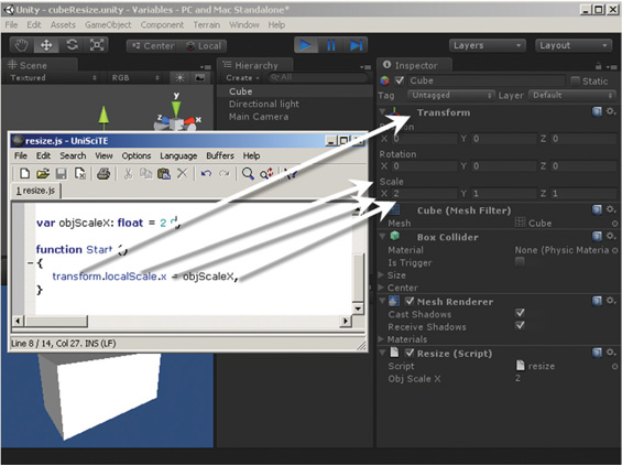
Step 11. Switch back to the script editor. Take a look at where the value of objScaleX is being used. It is changing the X value of the Scale in the Transform component of the GameObject the script is attached to, which in this case is the cube. This linkage is illustrated in Figure 1.27 showing Unity in play mode and the modified X scale in the Inspector.
FIG 1.27 How script links to the values of components attached to Game Objects.
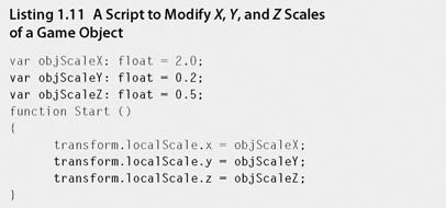
Step 12. In the script, add two more variables for adjusting the Y and Z scales and some code to link these values to the cubes transform component. The full listing of the new code is shown in Listing 1.11. Modifications are shown in bold.
![]() Note
Note
Do not use bold in your own code. Scripting should have no font effects whatsoever. Any coloration or bolding put in by the editor is for your own readability. It is put in automatically. Make use of this coloration and bolding to check that you have keywords spelled correctly.
Step 13. Save the script, return to Unity, and play to see the changes take effect. Change the values of these scales in the Inspector to experiment with the shape of the cube as the differing scales are changed.
![]() Note
Note
When you start programming it is extremely common to make typing errors and to leave out parts of code such as semicolons on the end of lines or missing brackets. If you make a mistake, Unity will detect it and give an error message. It shows up in red at the very bottom of the Unity window, as shown in Figure 1.28. If you get an error, double-click on the red message and Unity will take you to the line in the script editor where the error occurred. From there you can fix it, save the file, and return to Unity to try again.
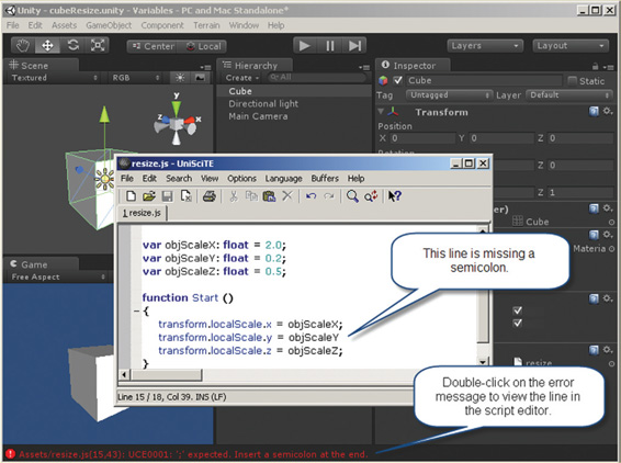
FIG 1.28 The Unity error message displayed when a semicolon is missing from a line of code.
1.5.5 Operators
There are two main types of operators in programming: arithmetic operators perform mathematical operations between variables and values and relational operators compare variables and values.
Arithmetic Operators
Basic math operators are shown in Table 1.2.
The assignment operator you may be more familiar with as an equal sign and the multiplication and division operators are a little different to those used in traditional math. Note from the JavaScript examples in Table 1.2 that values are placed into variables using the assignment operator. To use values already stored in a variable you simply refer to them in the equations using their name. It is exactly the same as high school algebra. More complex equations can also be created, such as
x = (y + z) / 3 + 8;
where parentheses work for order of precedence as they do in traditional algebra (e.g., the y + z between the parentheses would be calculated first).
TABLE 1.2 Common math operators used in all programming languages |
|||
| Operator | Arithmetic performed | Example in JavaScript | Value of x from example |
| = | Assignment | x = 2; | 2 |
| + | Addition | y = 5; | 8 |
| x = y + 3; | |||
| - | Subtraction | y = 15; | −10 |
| z = 5; | |||
| x = z - y; | |||
| * | Multiplication | y = 15; | 45 |
| x = x * 3; | |||
| / | Division | y = 15; | 3 |
| z = 5; | |||
| x = y/z; | |||
Relational Operators
Unlike arithmetic operators that can calculate a plethora of values, relational operators make comparisons that result in Boolean values (TRUE or FALSE). The most common operators are given in Table 1.3.
TABLE 1.3 Common relational operators used in all programming languages |
|||
| Operator | Arithmetic performed | Example in JavaScript | Value of x from example |
| > | Greater than | y = 5; | TRUE |
| z = 2; | |||
| x = y > z; | |||
| < | Less than | y = 10; | FALSE |
| z = 3; | |||
| x = y < z; | |||
| >= | Greater than or equal to | y = 4; | TRUE |
| z = 4; | |||
| x = z > = y; | |||
| <= | Less than or equal to | y = 3; | TRUE |
| z = 1; | |||
| x = z < = y; | |||
| = = | Equal to | y = 12; | FALSE |
| z = 16; | |||
| x = y = = z | |||
| != | Not equal to | y = 12; | TRUE |
| z = 16; | |||
| x = y != z | |||
An important thing to note in Table 1.3 is the use of = versus ==. One equal sign means assign or place a value into a variable, and the double equal sign means compare two values. First-time programmers often get these mixed up but with practice the differences become clear.
![]() Unity Hands On
Unity Hands On
Operators
Step 1. Download Chapter One/Operators.zip from the Web site, unzip, and open in Unity. In the Project, double-click on dynamicResize to open the scene. In the Scene you will see a small white sphere. Attached to the sphere is the script called grow.js.
Step 2. Double-click on grow.js in the Project to open the script editor. Note that there is already a variable added called growthRate. Modify the script to reflect the one in Listing 1.12.
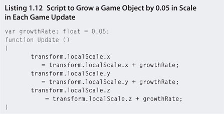
Step 3. Save the script and play in Unity. Note how the sphere grows slowly in size. This will continue until you stop playing. The Update function continues to run over and over again while the application is playing. Functions will be explored in depth later. For now, a simplistic explanation of what is happening is that the growthRate is continually being added to the current value of the localScale, thus updating it.
Step 4. Click on the Sphere in the Hierarchy. Ensure that you can see the Scale part of the Transform component in the Inspector. Now press play and watch as the x, y, and z values of the scale change constantly.
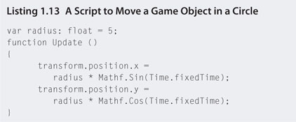
Step 5. In the Project, select Create and add a new JavaScript file. Call it revolve. To the file add the code in Listing 1.13.
Step 6. This new JavaScript file can be added to the Sphere while the grow script is still attached. Select revolve in the Project and drag and drop it onto the Sphere in the Hierarchy. Select Sphere in the Hierarchy and check the Inspector to see that revolve is attached. If it is not attached, try the drag and drop process again.
Step 7. Play the application. The Sphere will resize slowly while moving in a circular motion.
![]() Note
Note
The parametric form for a circle is used in Listing 1.13 to move a sphere around the circumference of a circle. These equations are based on modifying the x and y positions with cosine and sine functions and the time. The value of Time.fixedTime is a built-in Unity variable holding the time in seconds since the application started running. It is therefore a dynamic and constantly changing value. Unity also contains functions for all mathematical operations, such as Mathf.Sin() and Mathf.Cos().
It is not expected at this early stage in learning Unity to know this type of information. However, it can be handy to know where to find it, and the most invaluable resource you should have at your disposal is the Unity Scripting Reference. To access this information, while in Unity, select Help > Script Reference from the main menu. In the Web site that opens, try searching for Mathf and Time to see what is available to you.
1.5.6 Conditional Statements
Conditional statements allow the flow of a program to change when certain conditions are met (or not met). They rely on Boolean algebra for making decisions on which way code should flow. Conditional statements can divert code to other parts of code or can make the same statement of code repeat over and over.
Conditional statements, which are essentially the programmed form of Boolean algebra, cannot operate on their own. They need constructs around them to assess their value. The simplest form of these is an if-else statement.
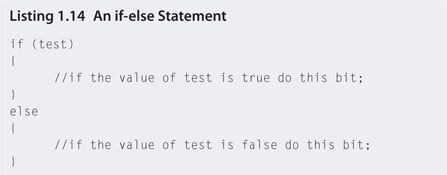
Used quite a lot in simple artificial intelligence programming, if-else statements make an assessment of a statement and do one thing if that statement is true and another (or nothing) if it is false. The if-else statement was used in the logic circuit application mentioned earlier in the chapter. Think of it as the type of logic you might use in deciding whether or not to wear a raincoat, thus:
if it is raining
wear a raincoat
otherwise
don't wear a raincoat
The if-else statement in JavaScript looks like that in Listing 1.14.
For example, consider the script in Listing 1.15.
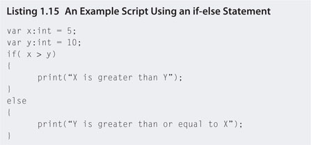
This program will print out “Y is greater than or equal to X” because the conditional statement inside the parentheses of the if statement will equate to false. If X were given a value of 20, the program would print out “X is greater than Y”.
![]() Unity Hands On
Unity Hands On
if-else Statements
Step 1. Download Chapter One/ifelse.zip from the Web site, unzip, and open in Unity. In the Project, double-click on falling to open the scene. In the Scene you will see a small white sphere. Attached to the sphere is the script called fallandgrow.js.
Step 2. Play the application. The sphere will appear to fall as its y position is changed constantly by the script.
Step 3. Open the fallandGrow.js script and make the changes shown in Listing 1.16.
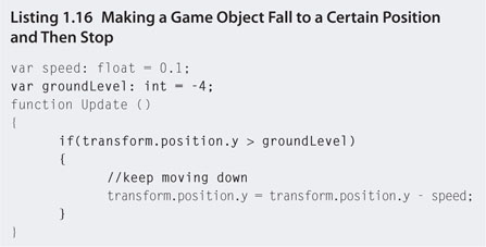
Step 4. Save and play. Watch as the sphere moves down the screen until it stops. What is occurring is that the y position is constantly being reduced by 0.1. While the value of the y position remains larger −4, the code inside the if statement will continue to be processed. As point y becomes greater than or equal to the groundLevel, that line of code is skipped and thus the sphere no longer has its y position modified.
Step 5. We are now going to modify the code to make the sphere start to grow when it stops moving. We know it will stop moving when the conditional statement in Listing 1.16 becomes false; therefore, by adding some growth code into an else we can have it execute, but only when the sphere stops moving. Update the fallandGrow.js script to reflect Listing 1.17.
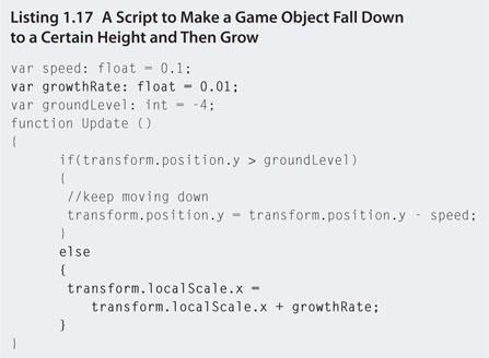
Step 6. Save and play. When the sphere reaches a y position of −4 it will stop moving and start to grow along its x axis.
The other programming construct that handles condition statements is a loop. A loop is a segment of code that runs over and over again until an ending condition is met. There are several types of loop constructs, but for now we are going to have a look at just one, the for loop.
Consider the code in Listing 1.18.
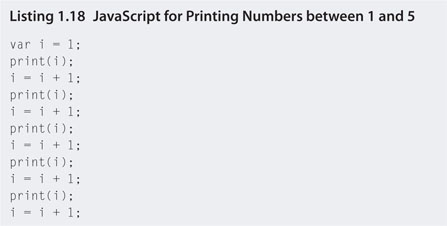
The output from this code would be
12345
as the variable i starts with a value of 1, is then printed, has one added to the value, and is printed again five times. Imagine printing out all the numbers between 1 and 100. It would be a lot of code.
Enter the for loop. The for loop reduces such repetitive tasks down into a few simple lines. The basic format of a for loop is shown in Listing 1.19.
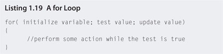
The first part of the for loop declares a variable and gives it an initial value. The second part performs a Boolean test on the value of the variable. If the test comes back true, the loop performs the code inside the parentheses. After the contents of the parentheses are finished, the variable value is updated and the test is performed again; if true, the inside part runs again. This continues until the test becomes false and the loop quits.
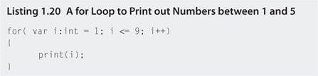
A for loop to perform the same action as Listing 1.18 is shown in Listing 1.20.
![]() Note
Note
Listing 1.20 introduces a new type of arithmetic used as a shortcut in programming. Writing
i++
is identical to writing
i = i + 1
It is a shortcut for adding one to the value of a variable. You can also write
i--
which will take one away from the variable i. More shortcut arithmetic is shown in Table 1.4.
TABLE 1.4 Shortcut arithmetic operations and their equivalent longhand |
||
| Shortcut | Longhand | Description |
| i++ | i = i + 1 | Adds one to the value of the variable and replaces the original value with the new one |
| i− − | i = i − 1 | Takes one away from the value of the variable and replaces the original value with the new one |
| i + = 2 | i = i + 2 | Adds two to the value of the variable and replaces the original value with the new one |
| i − = 2 | i = i − 2 | Takes two away from the value of the variable and replaces the original value with the new one |
| i * = 2 | i = i * 2 | Multiplies the value of the variable by two and replaces the original value with the new one |
| i /= 2 | i = i / 2 | Divides the value of the variable by two and replaces the original value with the new one |
for Loops
Step 1. Download Chapter One/forloop.zip from the Web site, unzip, and open in Unity. In the Project, double-click on stacked to open the scene. The Scene will appear empty. Attached to the Main Camera is the script called stackedSpheres.js. Play the file. A vertical stack of spheres will appear in the Game.
Step 2. Open stackedSpheres.js with the script editor. The code used to create the stack of spheres is inside the Start function. Each sphere is created individually and its y position is changed by 1 with each new sphere.
Step 3. Modify each line like this
sphere = GameObject.CreatePrimitive(PrimitiveType.Sphere);
to this
sphere = GameObject.CreatePrimitive(PrimitiveType.Cube);
Step 4. Save the script and replay the application. The stack of spheres will be replaced with a stack of cubes.
Although the sphere is being changed to a cube, note that the variable called sphere, which is being assigned the Game Object, does not need to be changed. This is because the name of a variable as far as the compiler is concerned is not important. It is only named sphere in this case for readability. It could have easily been called aPrimitive or aP.
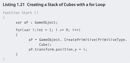
Step 5. Imagine that you now need to add another 50 cubes on top. This would be a big cut and paste and editing job as the y position would need to be incremented for each new cube. Instead we will replace all the code with just three lines (and a couple of parentheses) that will allow you to make the stack any height you like. Modify stackedSpheres.js to the code shown in Listing 1.21.
![]() Note
Note
Although the variable aP in Listing 1.21 does not have the keyword private included, it will not become exposed. Variables declared inside functions are called local variables and are only visible inside the function that created them.
Step 6. Save and play the application. It will produce the same result as the previous version. Note how the value of the variable i is being used to set the y position of each cube? Just another advantage of using a for loop.
Step 7. To put even spaces between each cube, change the line
aP.transform.position.y = i;
to
aP.transform.position.y = i * 2;
Step 8. Save and play to see the spaces created between the cubes.
Step 9. To create another set of cubes horizontally in the Game, add another for loop as shown in Listing 1.22. Note the use of the new variable j as the x position.
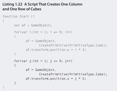
Step 10. Save and play. The result will look like that in Figure 1.29. You may need to move the camera around to see all the cubes.
Step 11. A few readjustments to this code can give you the power to create a matrix of 9 x 9 cubes. By placing one for loop inside the other, the nine repetitions of the horizontally placed cubes are compounded by the nine repetitions of the vertical cubes. Modify your code to that in Listing 1.23. On the first pass of the outer loop, the inner loop runs nine times. Then the outer loop moves onto its second pass. At this time the inner loop runs nine times again. This continues until the outer loop has finished its nine passes.
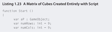
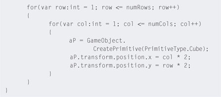
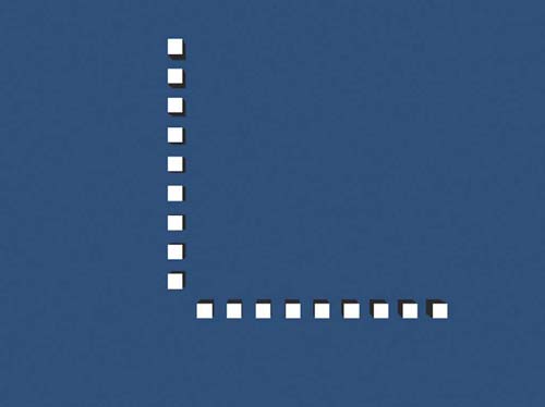
FIG 1.29 A column and row of cubes created entirely with script.
Step 12. Save and play to see the matrix of cubes as shown in Figure 1.30.
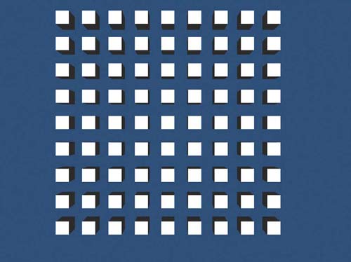
FIG 1.30 Game view of a matrix of cubes created with Listing 1.23.
1.5.7 Arrays
Sometimes a single variable is a less efficient way of storing data and objects. For example, consider changing the color of each of the cubes created in Listing 1.21, not initially at the beginning of the program, but randomly and constantly while it is running. In Listing 1.21, a single variable is used to create nine cubes. However, the variable itself only ever holds one cube at a time. Each time a new cube is created, the variable is overwritten with a new one. This means that after a new cube is created and assigned to aP, it is no longer possible to access the properties of the previous cube. Even the ability to change its position is gone. Therefore, we need the variable aP to hold not just one GameObject, but nine.
This can be achieved by making aP into an array as shown in Listing 1.24.
In Listing 1.24, the variable aP is no longer a single Game Object but an array. An array can store anything, including integers, floats, and Game Objects. If the original aP was a single storage box in memory, this new aP is a row of storage boxes where each box has its own index number.
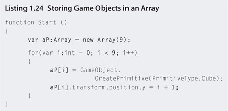
The first box in the array is indexed with a 0. To refer to each box individually, their names are aP[0], aP[1], aP[2], aP[3], aP[4], aP[5], aP[6], aP[7], and aP[8]. This is the reason for changing the for loop in Listing 1.24 to begin counting at 0. The variable i can be used as the array index. The first time the loop runs, aP[i] is equivalent to writing aP[0].
Because the y position of the first cube was initially 1 and i now starts at 0, the position must be set with i +1 to keep this consistent.
![]() Unity Hands On
Unity Hands On
Arrays
Step 1. Download Chapter One/Arrays.zip from the Web site, unzip, and open in Unity. In the Project, double-click on coloredCubes to open the scene. The Scene will appear empty. Attached to the Main Camera is the script called stackedColors.js. Play the file. A vertical stack of colored cubes will appear in the Game as shown in Figure 1.31.
Step 2. Open stackedColors.js in the script editor. Note that in the Update() function only four of the cubes are assigned a color. Also, the array declaration has been moved to the top of the script. This is to make aP a global variable available to all functions, not just Start().
Step 3. Modify stackedColors.js to the code shown in Listing 1.25.
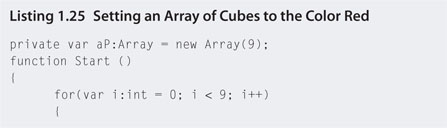
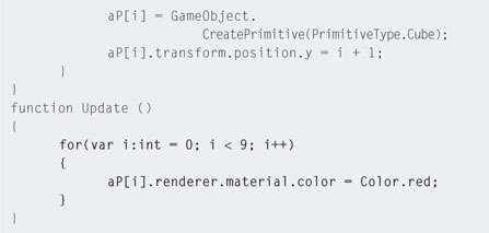
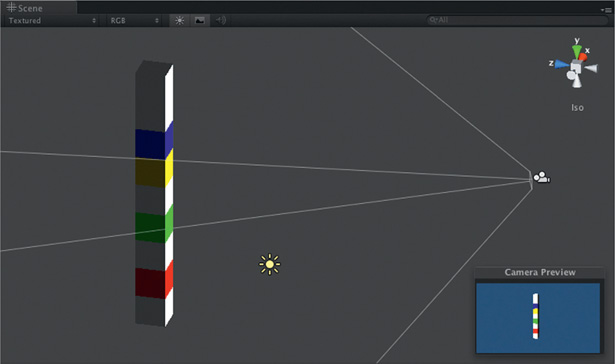
FIG 1.31 A stack of colored cubes created entirely with script.
Step 4. Save and play. The cubes created will have turned red. If you want to keep the cubes red, the code in the Update() function of Listing 1.25 would be better served inside the bottom of Start() as there would be no need to keep setting them to red in each main loop. However, we are now going to modify them to change to random colors.
Step 5. Modify the Update() function in your code to that in Listing 1.26.
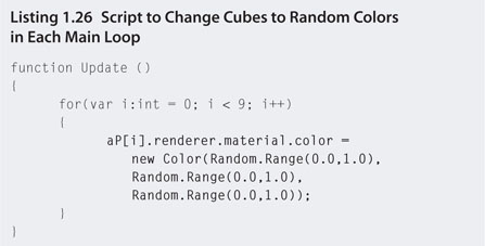
Step 6. Save and play. The cubes will change colors constantly. An explanation of the Color function is given in later sections.
1.5.8 Objects
Objects are complex data types. They consist of a bunch of variables (sometimes called properties) and functions (sometimes called methods). In most of the previous examples, you've already worked with objects. A Game Object is an object. A cube is an object. Most of the items you work with when coding that aren't integers, floats, strings, or characters are objects. A class defines the data type of an object.
Let's assume we have a simple class called Square. The class definition acts as a template for making many Square objects. Figure 1.32 illustrates how
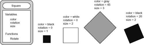
FIG 1.32 A Square class and four instances of the class.
the variables of the class can be set to create differing objects. Each object is called an instance of the class. In this case, setting the variable values for Square allows for a variety of Square objects to be created. So although they all look different, they are still squares and retain the essence of a square, which is to have four equal sides and 90° angles.
The functions of an object can be used to set the values of the variables or change the behavior. For example, the Rotate function in the Square class might update the rotation variable and thus change the orientation of the object.
![]() Unity Hands On
Unity Hands On
Objects
Step 1. Download Chapter One/objects.zip from the Web site, unzip, and open in Unity. In the Project, double-click on ChangeObjects to open the scene. The Scene will appear empty. Attached to the Main Camera is the script called createObjects.js. Play the file. A capsule will appear in the Game.
Step 2. Open createObjects.js in the script editor. Note that gameObj is a private variable created to hold a Game Object. In the Start() function, it is assigned a PrimitiveType.Capsule. The capsule is a complex game object where the attached components are also objects. For example, Transform is an object. Position, which is a part of Transform, is also an object.5 Visualizations of the Game Object, Transform, and Position classes, along with their locations in the Unity Editor, are shown in Figure 1.33.
![]() On the Web Site
On the Web Site
Game Object Definition
All of the variables and functions attached to a Game Object are listed in the script reference at http://unity3D.com/support/documentation/ScriptReference/GameObject.html.
Step 3. To change the location of the capsule you can access the x, y, and z position coordinates via the Transform component of the Game Object. Modify the script to that in Listing 1.27. Save and play.
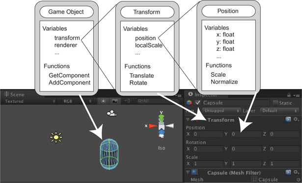
FIG 1.33 The Game Object class containing a Transform class that contains a Position class.
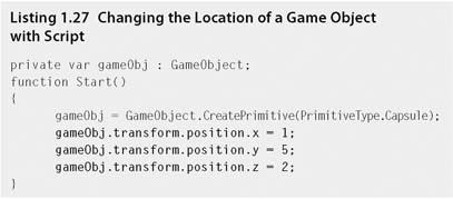
You can always change the location of a Game Object by typing values into the Transform component in the Inspector, although this can't be done while the game is playing. That is why scripting is more powerful.
Step 4. One of the functions available to the Game Object is AddComponent(). This script performs the same task as selecting the Game Object in the Editor and choosing an item from Component in the main menu. To add a physics component to the Game Object, modify your code to that in Listing 1.28. Save and play.
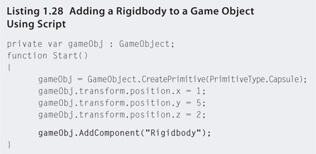
Step 5. The Rigidbody component is used by the physics system. As you play your new script, the capsule will fall due to gravity until it hits the plane in the scene. The collision event will cause the capsule to stop dead in its tracks. If you examine the capsule in the Inspector while the script is playing, you will notice that the capsule has a Collider component. This is used by the physics system to determine the boundary area of the object in order to calculate collisions. You can access the collider and change its values in the script. Modify your script to that in Listing 1.29.
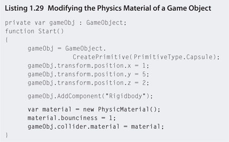
Step 6. Save and play. We will examine physics in more depth later in the book. For now, just accept that this new code makes the capsule bouncier, and the physics engine will cause it to bounce when it collides with the plane. PhysicsMaterial in Listing 1.29 is another type of object. Note the use of the keyword new as it is being assigned. On this line a new variable called material is being created and assigned a new PhysicsMaterial. The new keyword creates an instance of the object. After an instance is created the values can then be manipulated via referencing the variable to which it has been assigned—in this case, material.
Step 7. So far we have modified a game object via a script attached to the camera. Scripts can also be attached directly to a game object. From the main menu select GameObject > Create Other > Sphere. A sphere will appear in the Scene. Select the sphere in the Hierarchy and press the W key. Use the axes in the Scene to move the sphere above the plane.
Step 8. In the Project, select Create > JavaScript. Rename the script spherePhysics, attach it to the sphere by dragging and dropping it from the Project onto the sphere in the Hierarchy, and open it in the script editor. Add the script in Listing 1.30.
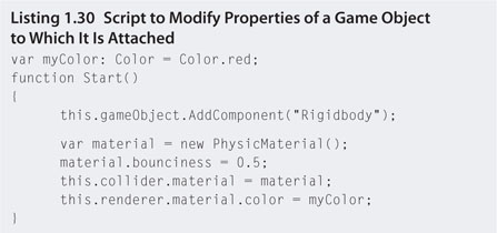
Step 9. Save and play. Now the script is attached to a game object; it can directly reference the object with the keyword this. There is no need to create the object because it already exists in the scene. Because the variable myColor is exposed, you will be able to change it in the Inspector.
Step 10. From the main menu select GameObject > Create Other > Cube. A cube will appear in the scene. Position it above the plane and to one side of the sphere. Attach the spherePhysics script to the new cube.
Step 11. Play. Note that the new cube behaves in the same way as the sphere. This is because the script in spherePhysics applies itself to the object to which it is attached. As a result, the cube turns red and falls with the same physics attributes at the sphere. Generic script like this can be added to any game object.
Step 12. Because the myColor variable is exposed, it can be changed in the Inspector before playing. Select the cube from the Hierarchy and change myColor in the Inspector to green.
Step 13. Play. Note that the sphere remains red but the cube is now green. Both are using the same script but different versions of it. You could also expose the variable for the bounciness and set it to different values for the sphere and cube in the Hierarchy, as shown in Listing 1.31.
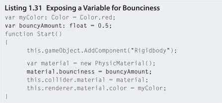
![]() Note
Note
Bounciness in the physics engine is a float that only takes values between 0 and 1 where 0 is not bouncy and 1 is fully bouncy.
1.6 A Game Art Asset Primer
This primer will not teach you how to create game assets. Such topics are books on their own. It will, however, point you in the right direction to get started creating your own assets, as well as where to find already made ones. Most importantly, this primer will introduce you to the different types of assets and how to get them into a Unity game.
When it comes down to it, there are two types of art assets used in games: 2D and 3D. Two-dimensional art assets are the most used, as everything in the game has a 2D visual element. From trees to buildings, terrain to explosions, and characters to user interfaces they all include 2D art. In addition, normal maps and shading maps are also 2D images.
1.6.1 The Power of Two Rule
Since the inception of computer graphics, people have been trying to create superior and higher resolution images. The quality has not been restricted by the ability of art to create, but by the computer hardware's ability to process. In the mix with computer games is the need to quickly render frame after frame of real-time animation that changes with game flow influenced by user input. Unlike an animated movie in which the contents of each frame are known from the outset, the interactive nature of a computer game means that the artist will never know what will be in any particular frame. The game itself needs to render frames on the fly. This requires a lot of processing power. This is why, over the years, as hardware performance has improved, so too has the quality of game graphics.
However, as a game developer you will still want to push the boundaries of quality and knowing a few simple tricks can help you optimize your art assets to get the best out of the graphics processing. One such trick is to follow the power of two rule.
Computers continuously process data in cycles in order to push it through the processors, whether it be the central processing unit or, more commonly for graphics, the graphical processing unit. Processors can only handle so much data in one cycle and therefore it is chunked into packages of certain sizes.
Earlier in this chapter we examined the most elementary values in computing. They were 0 for on and 1 for off. These values are the basis for binary code that is used to encrypt all values in computer memory. The smallest amount of computer memory is a bit. It can store either a 0 or a 1. If we put two bits together they can store four values: 00, 01, 10, or 11. Three bits can store eight values: 000, 001, 011, 010, 011, 100, 101, or 111. In fact, the number of values that can be stored is 2 to the power of the number of bits or 2number of bits. Therefore, eight bits (called a byte) can store 28 or 256 values.
A computer processor has a limited number of bytes it can push through in one cycle. By making an image file a power of two in dimensions, it optimizes the number of cycles required to process it. For example, if an image were nine bytes in size and the processor could process four bytes per cycle, the first two bytes of the image could be processed in two cycles. On the third cycle the ninth byte would be processed. This would mean three whole empty bytes of space wasted during the third cycle.
Imagine it as though you have a dishwasher that can hold four plates. You need to wash nine plates. You would do two full cycles and then have only one plate in the third cycle. For the same amount of dishwashing you could have invited another three guests to dinner! This illustration is exacerbated as file sizes become larger.
If you sacrifice processing cycles, you will sacrifice quality and speed. Ideally, images should have width and height values that are a power of two, for example, 2, 4, 8, 16, 32, 64, 128, 256, etc. The image does not need to be square; for example, the width could be 16 and the height 128. Making an image this size in dimension will lead it to occupy a space in computer memory that is also a power of two in size.
A digitized image is not just the size of its width and height, but also its depth—its color depth. The color depth is defined as the number of bits required to store the color values of each pixel. When a pixel is colored according to its red, green, blue, and alpha values that take up 8 bits (1 byte) each, it is said to have a color depth of 32 bits.
Therefore, an image that is 16 x 32 pixels with a color depth of 32 bits is 16,384 bits in total size. This is equal to 214; a power of two! Because computer memory processes in chunks whose sizes are also a power of two, it will result in an optimized use of each processing cycle.
But what happens if your texture is not a power of two? Your image will be resized or rescaled. If it is rescaled, the game engine will make it into an image with a power of two width and height closest to that of the original. This means the original image will be squashed or stretched to fit into the new space. This could result in undesirable distortions in the texture. If the image is resized, the original could be cut off or extra blank space added around the edges in order to make it fit into a power of two texture. Either way, the result could be something that you don't want as it may misalign your UV mapping.
![]() Unity Specifics
Unity Specifics
Textures
Unity will accept nonpower of two images as textures but it will rescale them. It accepts widths and heights of 2, 4, 8, 16, 32, 64, 128, 256, 512, 1024, or 2048 pixels. The majority of image file formats are accepted, including psd, tiff, jpg, tga, png, gif, bmp, iff, and pict. A multilayered psd file created with Photoshop will appear flattened inside the Unity Editor; however, the layers will still be there and editable when reopened in Photoshop.
Adding Textures to a Model
Step 1. Download Chapter One/Texturing.zip from the Web site, unzip, and open in Unity. In the Project, double-click on texturedemo to open the scene. The Scene will open with a shaded female model. In the Hierarchy, click on the little triangle next to the word Female to expose the entire mesh hierarchy. You will now see that the submeshes of eyes, face, hair, pants, shoes, and top are listed beneath the parent of Female as shown in Figure 1.34.
FIG 1.34 Project view showing shaded model and mesh hierarchy.
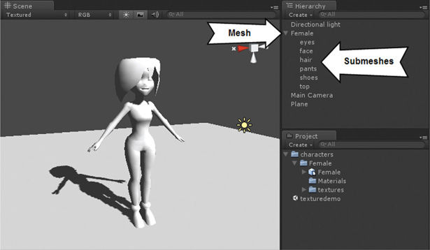
Step 2. In Project, select Create > Folder and call it Materials. Highlight the Materials folder and select Create> Material from the small drop-down menu. Rename the material to top.
Step 3. With top in Project highlighted, at the very top of the Inspector select the Shader drop-down list and click on Bumped Diffuse. The Inspector will reveal the properties of Main Color, Base (RBG), and Normalmap as shown in Figure 1.35.
FIG 1.35 A Bumped Diffuse Shader opened in the Inspector.
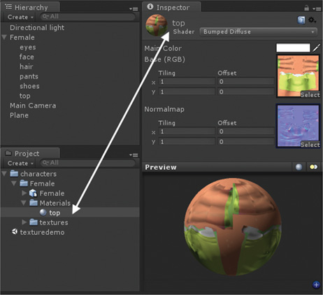
Step 4. The Main Color is a color added to the color of the texture. If you leave it as white it will have no effect. For now leave it as white. In the texture box to the right of Base (RGB) click Select. From the image picker that pops up select the female_top-1_green. For the Normalmap, click on Select for the texture box and pick out female_top-1_normal by double-clicking on it. If the full name of the texture is not displayed beneath it, clicking once on the image will reveal the full name at the bottom of the picker, as shown in Figure 1.36.
Step 5. Drag the top material from Project and drop it onto the top mesh in the Hierarchy. In the Scene and Game the model will now appear with texturing on the top of the body.
Step 6. Repeat the process for the face, hair, pants, and shoes submeshes (not eyes), selecting appropriate Base (RGB) and Normalmaps from the texture picker.
Step 7. Create a new material for the eyes. In the Inspector, set the shader for this material to Specular. Select an eye image for the Base (RGB) Gloss (A) texture. The Specular Color property for this shader sets the color that is reflected from the surface on any shiny parts. The Shininess value changes the surface value from highly glossy to dull.
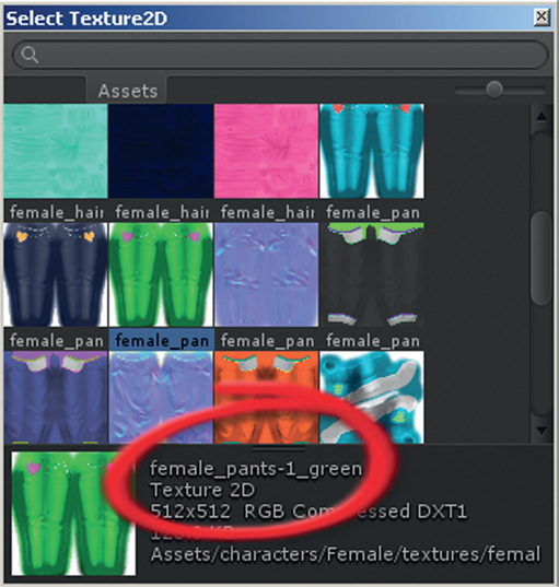
FIG 1.36 Unity's Texture Picker with Image Full Name Selected.
Add the material to the eyes submesh and change the specular color and shininess values to see their effect.
Step 8. To give the ground plane a texture, open a browser window and search Google for “seamless grass texture.” Switch the search to Images. A seamless texture is one that neatly tiles both horizontally and vertically across a surface where the patterns meet exactly at the seams. Large areas such as terrains use seamless textures as it is less costly than one very large texture. From the search, locate a texture that is a power of two in size (and free to use), as shown in Figure 1.37. Download it to your desktop.
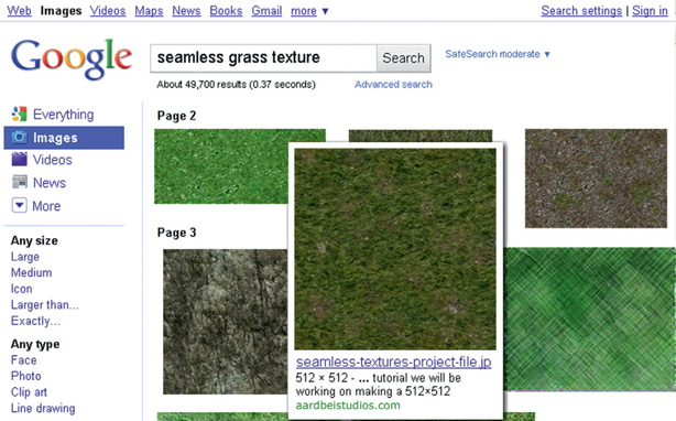
FIG 1.37 A search for seamless grass textures in Google image search.
Step 9. Drag the image file from your desktop and drop it into the Project. Unity will load it for you automatically.
Step 10. Create a new material called grass. Leave the shader as the default Diffuse. Drag and drop the grass material onto the ground plane. Select Plane from the Hierarchy and find the grass material in the Inspector. Beneath Base (RGB) are Tiling values. These set the size and alignment of the texture on the surface. For example, setting Tiling's x to 5 will cause the texture to repeat five times across the surface. The bigger the tiling values, the smaller the tiles. Try setting the Tiling values to see the effect in the Scene.
1.6.2 Using Other People's Art Assets
Sometimes it's not worth your time recreating 3D models and textures when they are available on the Web. For example, if it will cost you a week's worth of work to create a model that someone is selling on the Web for $50, then it is worth purchasing if you can afford it. There are also many free 3D models available for use under a variety of licensing formats. Others are royalty free, which means that you pay for them once and then use them as many times as you like under the terms of the license.
There are many online Web sites for which you can freely sign up and download models for use in your own games. Some of the better ones include:
- TurboSquid: http://turbosquid.com
- Exchange 3D.com: http://exchange3D.com
- 3D Cafe: http://3Dcafe.com/
The model format used most widely and accepted in game engines is 3Ds. This was the original file format created by Autodesk's 3D Studio DOS release. This format can also be created and modified by Autodesk's 3D Studio Max, Maya, and Blender.
![]() Unity Specifics
Unity Specifics
3D Models
Unity's native 3D model format is fbx. This can be created with Autodesk's 3D Studio Max. It will also import and use max files, but only if 3D Studio Max is installed on the same machine. The native files produced by Blender are also highly compatible and can be added seamlessly to projects, as can 3Ds formats. To add a model into your project, simply drag and drop it and any associated textures into the Project.
![]() Unity Hands On
Unity Hands On
Adding a Model to a Unity Project
Step 1. Create an account on TurboSquid by visiting http://turbosquid.com and following the prompts.
Step 2. Search on Turbosquid for “car” or something else if you wish. Ensure that you set the filter to 3D Models and sort by Lower Prices to have the free models appear first.
Step 3. Look through all the models and select one you like. Note that the file format type is listed beneath the image of the model. Look for a 3Ds, fbx, or blend file. Download the file to your desktop.
Step 4. If the files are zipped, unzip them. Some files will be single mesh files such as a 3Ds; others may have textures with them. Three freely downloaded models and how they unzipped are shown in Figure 1.38: a Ferrari model created with Blender, a 3Ds model of an alien with a texture, and a Mini Cooper Blender model in its own folder.
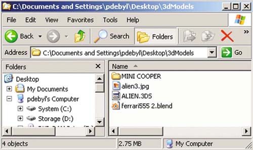
FIG 1.38 How three model files downloaded from TurboSquid appeared with unzipped.
Step 5. To import the models into Unity, select all the files associated with the model and drag and drop into the Project. If the model contains textures, ensure that you have the model file and the texture file in your selection. If the model and associated files are in a folder, drag the entire folder into Unity. The way they will appear is shown in Figure 1.39. Don't worry if you receive a couple of Unity error messages.
Step 6. Using free models is mostly a potluck as to the ones that will work in Unity. Sometimes they will be too big (Unity only allows 65,000 vertices per mesh), inside out, or just missing textures. If the model you get appears this way, go back and find another model.
![]() On the Web Site
On the Web Site
A Model That Works
If you are having difficulty finding a model that works, one can be downloaded from the book Web site under Chapter One/tyrannosaurus_rex.zip.
FIG 1.39 A view of the Project after importing three downloaded models.

FIG 1.40 Models imported and viewed in Unity.
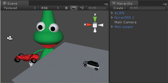
Step 7. Once the models are in the Project, find ones with a small cube icon next to them. Drag these into the Hierarchy or Scene to add them into the application. The three models shown in Figure 1.39 are imported into Unity as shown in Figure 1.40. In this case, the Ferrari model was too big and parts of the wheel are missing, the alien model was okay, and the Mini Cooper included a ground plane. Also note that the scaling for each mesh is different. This will be due to the scaling the original modeler used.
Step 8. To resize the models, select them and use the Inspector to change their scale component. Alternatively, press the “R” key and use the resizing axes in the Scene. If you get a model without any texturing, but have an image for the texture, create your own material, select the texture for it, and apply the material to the mesh.
1.7 Summary
Game art and game programming are two sides of the same coin. This chapter examined the complementary nature that both art and programming play and suggested that anyone can learn to program and anyone can understand the logic behind art. While you may not become fluent in both art and programming, you will gain knowledge, and appreciation for both domains is important for working in the games industry. In addition, it is absolutely necessary for artists working in the area to appreciate the technical limitations placed on their artwork by game engines and computer hardware. Some simple planning ahead and modeling within the restrictions of a games platform can eliminate a lot of future time, money, and heartache.
1 And mathematics, physics, information technology, etc.
2 Named after George Boole, the 19th-century mathematician who first defined algebraic systems of logic.
3 If you are interested in exploring this topic more, see http://en.wikipedia.org/wiki/Primitive_data_type.
4 For more information about naming conventions, see http://en.wikipedia.org/wiki/Naming_convention_(programming).
5 Actually, Position is a structure. This is another data type with complex variables and functions. It acts so much like an object that we will just treat it as one rather than complicate matters.