
CHAPTER 3

Animation Mechanics
Animation is about creating the illusion of life. And you can’t create it if you don’t have one.
Brad Bird
3.1 Introduction
Animation is the underlying mechanic on which the visual aspect of computer games is built. It is the illusion of movement created through the display of a rapid succession of images, each slightly different from the other, creating the impression of motion. Animation is possible because of biological phenomena involving the human eye.
Originally, the perception of motion was explained by a theory known as persistence of vision, which refers to the afterimage that appears on the retina for approximately one-twenty-fifth of a second. You will notice this effect after staring at something and then closing your eyes. A negative type of imprint will be apparent. This effect is exaggerated if you look at a high-contrast image such as the shadowed side of a tree with the sun shining through from the other side. It was initially thought that humans saw animation when the afterimage from one still shot merged with the next. Although persistence of vision is a term still used to explain our ability to see movement when there is none in film and cinema, the theory was discredited as the main explanation by German Gestalt psychologist Max Wertheimer in 1912. Rather he proposed that the perception of motion was a psychological phenomenon called phi. Phi, in short, is the way in which the human brain automatically fills in the gaps between the images we see and therefore creates a perception of seamless motion.
The traditional technique for producing animation was to hand draw each image, known as a frame, and display them one after the other. Early Disney cartoons were produced in this manner. In order to provide smooth motion, the frames need to be shown at 24 frames per second. These frames are shot in twos such that each still image is displayed on two frames of film. This means that 12 drawings are required for 1 second of film.
For modern computer games, frame rates between 30 and 100 are acceptable. Of course, if there were no motion on the screen, a frame rate of 1 would be adequate. The frame rate in a computer game will differ depending on the background processing that is occurring during any given game loop. Ironically, fast action-paced games with lots of moving objects need to run at a higher frame rate in order for the player to take all the action in, although all the extra processing would be taxing on the processor and could lead to low frame rates.
Animation in the very first computer games was the result of using vector graphics to draw an object on the screen, clearing the screen, and redrawing the object at a slightly different location and rotation. Essentially, each frame was being drawn on the fly by an algorithm—the reason being that the computers of this time did not have memory available for storing art assets created by others; not to mention the absence of digital paint programs to produce them. For very simplistic graphics this worked effectively. The use of real-time drawing in one of the first computer games, Spacewar! (produced in 1962), is shown in Figure 3.1.
When read-only memory was introduced to arcade games in 1974, it allowed for the storage of predrawn graphics along with the game’s program. The game could then load the various graphical assets and integrate them into the animation on the screen. These two-dimensional bitmaps were first referred to as sprites.
3.2 Sprites
Loading a 2D image onto the screen and redrawing it along a path will create a simple animation. This very principle is illustrated in the rocket ship workshop from Chapter Two in which the static rocket ship image is moved around the screen. The rocket ship and planet are sprites. In these examples,
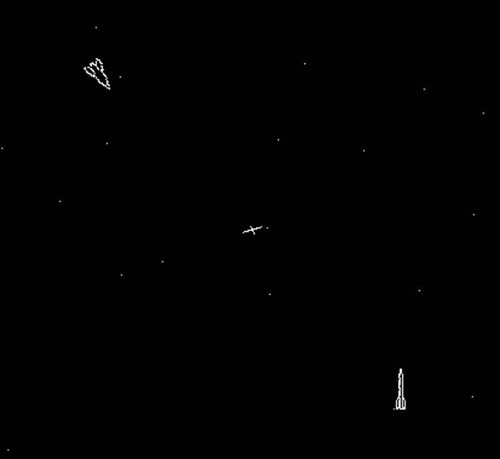
FIG 3.1 Spacewar!
sprites are dealt with by placing a texture representing the graphic element over a plane game object. The plane is then moved around the screen to create an animation. Both the rocket ship and the planet each have its own materials representing the different images.
The more materials used in a game, the less efficiently it will run. This is closely related to the way in which the power of two images is processed. In the case of Unity, each material adds extra load inside each game loop. This load is called a draw call. A draw call occurs when rendering commands are processed by the computer’s graphics processor. Each material used equals one draw call. Therefore, if you have 100 materials it will cost you 100 draw calls.
![]() Unity Hands On
Unity Hands On
Investigating Draw Calls
Step 1. Create a new Project in Unity.
Step 2. Add two planes to the Scene.
Step 3. Position the camera so that the planes are visible in the Game.
Step 4. Click the Stats button in the top right of the Game tab. Note that the number of draw calls is currently 1.
Step 5. Create two new materials in the Project called Material 1 and Material 2. You don’t need to give them any particular settings.
Step 6. Add Material 1 to one plane and Material 2 to the other. Now look at the number of draw calls. It will be equal to 2, the same as the number of materials.
Step 7. Right-click on one of the planes in the Hierarchy and select Duplicate. The number of draw calls will remain at 2 as there are still only two materials being used.
Step 8. Create another material and add it to the latest plane. The number of draw calls will increase to 3.
As the number of draw calls increases, the slower your game will run. Albeit a great number of draw calls would be required to make any noticeable difference on a high-performance gaming machine. However, if you port your application to a mobile device, a dramatic effect on performance is seen after around 15 draw calls.
Materials aren’t the only things that will increase the number of draw calls. As the polycounts of the meshes in the game environment increase, so too will the draw calls. However, polycounts don’t have a one-to-one relationship with performance as materials do. Therefore, it is essential to consider the way in which sprite materials are handled.
3.3 Texture Atlas
Considering that a single material made from a texture that is 512 × 512 will take the same number of draw calls as one that is 32 × 32, it seems a waste to use only a 32 × 32 texture. Therefore, if the 32 × 32 image were put into a 512 × 512 image, there would be plenty of space in that image for other small images. Combining images into one texture is a common technique in games and is called a texture atlas.
In a texture atlas, each smaller image has its own set of pixel coordinates and a width and height. To create such an atlas you can use a paint program such as Photoshop or Gimp to combine smaller images into a single larger one. Figure 3.2 shows an example texture map in Gimp. Each image is placed such that a bounding box around it does not overlap with any other image. This allows for easy extraction of single images from the texture map in the game engine. In this example, the bounding box for the small car starts at (0,0) pixels and ends at (40,40) pixels. Gimp is useful for creating texture atlases; the pixel location of the mouse cursor is shown in the lower left-hand corner of the window. This makes it easier to extract the bounding boxes for each image. In Gimp, however, (0,0) is in the upper left-hand corner of the image. If you were to use Adobe Illustrator, (0,0) is

FIG 3.2 A texture atlas in Gimp showing the boundaries of a small car sprite image.
in the bottom-left corner. Keep this in mind when you are grabbing pixel coordinates. If your texture appears upside down, it could be because the y axis is inverted. This isn’t a problem, just something that needs to be taken into consideration in your game scripts.
The coordinates of the bounding box are then used to manipulate the UV values of a mesh such that only the pixels inside the bounding box appear on the mesh as its texture. This requires a thorough understanding of vertices and UVs.
While the vertices of a mesh can have any value in 2D or 3D space, UVs are always specified between 0 and 1.
![]() Unity Hands On
Unity Hands On
Modifying Mesh UVs for Sprite Mapping
Step 1. Download Chapter Three/StaticSprites.zip from the Web site. Unzip and open the project with Unity. Open the scene called isostreet. You will see an isometric view of a street scene with a number of smaller icons in the center. The camera is set to orthographic. As we are using only sprites and no true 3D objects, the perception of depth is not required. Play. Nothing will happen.
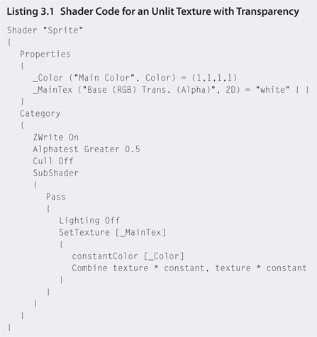
Step 2. In the Project create a new Shader. Edit the Shader by double-clicking to open and add the code given in Listing 3.1. Because sprites are two dimensional, usually you don’t want them affected by a light in the game environment; so they don’t look shaded and washed out, a special shader for them is a good idea.
Step 3. The groups of icons in the center of the Game are drawn on the SimplePlane object in the Hierarchy. Select it and note the texture atlas material. The objective is to isolate one of the icons and draw it on the plane when the game is run. To do this we need to modify the UV values with script. Create a new JavaScript file called setSprite and add the code in Listing 3.2.
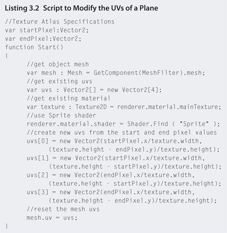
Step 4. The coordinates to be used are inverted in the y axis as specified in Gimp; therefore, the code turns them up the other way by subtracting all y values from the texture height. If you used pixel coordinates with (0,0) in the bottom-left corner then you would just leave out the texture.height part. Attach the new script to SimplePlane.
Step 5. Select SimplePlane in the Hierarchy and locate the attached script in the Inspector. Set the startPixel and endPixel values to (0,0) and (40,40), respectively, as shown in Figure 3.3.
Step 6. Play. The texture on SimplePlane will now become the little blue car. Because the code is focusing on a smaller part of a large image and stretching that part over the same sized surface, the final texture may look pixilated or too fuzzy. To fix this you will need to rescale the SimplePlane to suite. This can be done in the Inspector in the transform component by changing the x and y scale values.
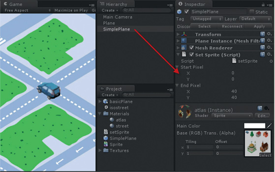
FIG 3.3 Setting pixel values for UV modification.
Step 7. To add more sprites to the scene, duplicate SimplePlane, and change its location and the start and end pixel values. Using the available icons in the texture map you will be able to make a nice street scene. SimplePlane can also be treated like the rocket ship from a previous workshop, and code can be added to move it around in the game.
![]() Note
Note
Specifying UV Values
The listing in Listing 3.2 assumes that the pixel values for the sprite textures have the y values flipped. If you find that your sprite textures are upside down, change the code for all y values to endPixel.y/texture .height.This will turn the images up the other way.
3.4 Animated Sprites
Technically, any 2D image used as an object or character in a game is a sprite. However, the term is associated more often with a set of 2D animations representing specific movements of a game object. In this case, a sprite consists of a set of images that combine to animate specific gestures, such as walking, running, and jumping. The sprites are imported into a game engine and code is used to control how the frames are presented in the game environment to give the illusion of character movement.
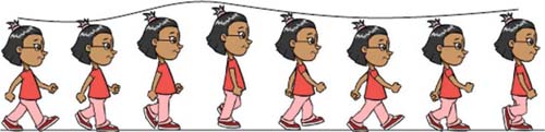
FIG 3.4 Half of a walk cycle where the other half would be a reversal of the arm and leg positions.
The animation images for a sprite are drawn based on the movement cycles originally developed for cartoon characters. Preston Blair, an acclaimed animator who worked for Disney, Warner Bros., and Hanna-Barbera, published many illustrations demonstrating various character poses through a series of movement cycles. Some of them can be found at http://www.animationarchive.org/pics/pbanimation26-big.jpg. The first of these cycles often referred to when teaching elementary animation is the walk cycle shown in Figure 3.4. Note in the walk cycle here, and the others by Preston Blair, the use of motion arcs for natural movement. The character rises and falls with each step.
Each of the images in Figure 3.4 becomes a single frame for the sprite. When these frames are cycled through in the game it gives the illusion of a walking character.
![]() Unity Hands On
Unity Hands On
Creating a Texture Atlas with Code and Animated Sprite
Step 1. Create a new Unity project.
Step 2. Create a new Shader called Sprite and copy the code from Listing 3.1.
Step 3. Add a plane into the Scene and orientate it such that the visible side faces the camera.
Step 4. Download Chapter Three/walkcycles.zip from the Web site. Unzip the file and add all the images into the Project.
Step 5. Create a new JavaScript file called AnimatedSprite and add the code shown in Listing 3.3.


Step 6. Attach AnimatedSprite.js to the plane.
Step 7. With the plane selected in the Hierarchy, locate the AnimatedSprite script component in the Inspector. Set the Size value for Textures to 16 and drag and drop all the walk cycle images onto the elements where Element 0 is walkcycle1, Element 1 is walkcycle2, and so on.
Step 8. Play. The texture atlas will be created and applied to the plane. In the game you will be able to see an image on the plane made up of the 16 walk cycle textures. The effect can be seen better if you stretch the plane out by modifying its x scale as shown in Figure 3.5.
Step 9. Ensure that the plane scale is (1,1,1). Now instead of all 16 images appearing on the plane at once we only want 1. To achieve this, the texture scale on the plane should be reduced to 1/16th of its size along the x axis. This can be done in the Inspector where the tiling and offset values for a material are set. However, because the atlas is being created dynamically (i.e., as the program runs), you’ll want the code to set it to align with the number of frames in the walk cycle. To do this, modify AnimatedSprite.js as shown in Listing 3.4.

FIG 3.5 The created texture atlas.

Step 10. Play. The first frame will appear on the plane.
Step 11. Next, to animate the sprite, the frames need to change. Changing each Update() would be erratic and too fast as the time between Updates() is not fixed and depends on the processing occurring in the game. We therefore need to implement a timer that can switch the frames for us. Modify AnimatedSprite.js as shown in Listing 3.5.

Step 12. Play. The sprite will be animated.
Step 13. To change the speed at which the animation plays, select the plane in the Hierarchy and locate the Framerate variable of the AnimatedSprite component in the Inspector. This value controls the number of frames drawn per second. Change it to 100 to see the animation play faster and change it to 1 to see it run slower.
Step 14. Download Chapter Three/background.psd from the Web site. Add a new plane to the scene behind the sprite and put this new texture on it. It is a city background scene. Stretch the plane out to accommodate the texture. Set the material shader to Sprite to make it display correctly without lighting. If the image is upside down, rotate the plane by 180° around the y axis.
Step 15. Create a new JavaScript file named scrollBackground. Add the image scrolling code from Chapter Two, repeated here in Listing 3.6 for your convenience. Attach the JavaScript to the new plane.
Step 16. With this new plane selected, change the UVSpeed to (0.1,0) in the Inspector.
Step 17. Play. The background will scroll, making the character appear to walk along the street.

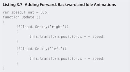
Step 18. To move the character itself with the arrow keys, create a new JavaScript called walk.js, add the code in Listing 3.7, and attach it to the character’s plane.
Step 19. Play. The arrow keys will move the sprite back and forth in front of the background. Remove the scrolling script from the background to get a better idea of how the character is moving.
Step 20. With the walking speed set to 0.5 the character appears to slide across the ground. This is a common error made by beginner animators when creating walk cycles and placing the character into an environment whether it is in 2D or 3D. The idea is to get the walk cycle speed to match the motion speed so that each foot appears to be planted into the ground. For this character, a speed of about 0.06 is a close match for a frame rate of 15. Try this out.
Making Your Own Sprite Frames
One of the easiest ways to create your own sprites, instead of drawing each frame by hand, is to use a software package that will do it for you. Adobe Flash has an export to image option that will allow you to create single frames from an animation and save them as a sequence of .png files.
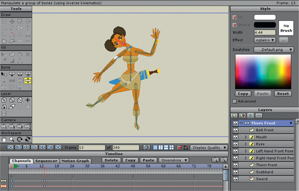
Anime Studio Pro is a 2D animation software package that will take an image of a character and allow you to add your own bones (see Figure 3.6). You can then manipulate these bones to pose the character. After an animation has been created, Anime Studio Pro provides export features that will create a sequence of .jpg or .png files that can then be used on sprites in Unity.
FIG 3.6 Anime Studio Pro.
![]() On the Web
On the Web
More sprites: http://www.touchofdeathforums.com/resources.php
GIMP http://www.gimp.org
3.5 Baked 3D Animations
Calculating animations in real time through kinematics is a very processor-costly method for animating game characters. While this method can certainly produce spontaneous interactions with characters, far more artificially intelligent controls need to be programmed to make them feel real. If you examine game characters closely you will notice that they repeat the same actions in exactly the same way over and over. This is because it is less effort on the part of the animation to make; for example, why use five different walk animations when just one will suffice? It does not add anything more to a game having characters that can select from different walking styles as they see fit.
If you stop to observe ancillary characters in the crowd such as those in Splinter Cell or Grand Theft Auto, you will be able to spot their walk cycles and other repeated actions. Because the purpose of the game in these cases is not to eye the crowd, the same repeated walk cycle is not that important. You may also find a game hero climbs a drainpipe the same way he climbs a rope. Reusing animations is just a trick to get better performance out of a game and a way to keep the development budget down. In the end it is how these animations are used and how the game environment is designed around these limitations. For example, the animation for climbing a ladder could be used for scaling a building or a trellis if the objects are designed to have handholds and footholds in similar positions to a ladder.
When animations are fixed and not manipulated in real time by the program, they are called baked. This means that the entire animation sequence is calculated beforehand and that the program receives a set of model transformations for each frame.
Because the character modeler cannot possibly know at the time of animating how the player is going to direct and move the character, it is impossible to create a long strung out animation, for example, showing the character running up the road, jumping over a fence, and rolling through a window. If the player decides the character should not jump over the fence but rather hop on the nearest motorbike, a single long animation will not allow for visualization. Instead, animations are broken into short action segments that can later be put together in any order to facilitate fluid animation. Such segments might include walk, run, and jump cycles. Depending on how the player wants the character to move, he can then run, jump, run, and walk or walk, jump, jump, run, and walk seamlessly.
This means that each animation segment should start and end with the character in the same pose. When the next segment is added, there is no obvious gap in the sequence. As shown in Figure 3.7, the initial frame for the character’s idle, run, walk, and shoot down animations has the character’s feet and legs in exactly the same position. No matter what the sequence of

FIG 3.7 Starting frames for four different animations performed by the same character.
actions, the full movement of the character will appear fluid. In a situation where the animation switches to the shoot down, the arms and shoulders will move away from the initial poses of the others. If this is a very small movement, and given the legs don’t move, the change in pose will appear as a simple frame change in any other segment.
If a situation arises where the character needs to go from a walking to a crawling action, two in-between sequences are required to stitch the animations together: one for getting down and one for standing up. Sometimes a single animation is reused for its reverse action. For example, getting down is reused for the standing up and walking forward is reused for walking backward. However, if you have a close look at both these examples, the results are usually very unconvincing and ruin the entire effect.
Baked animations can be made in software modeling and animation tools such as Autodesk’s 3DS Max and Maya. The native format for animations in Unity is fbx, which can be created with both these applications. Once the fbx sequences have been imported into Unity, Script can be used to control how they play.
![]() Unity Hands On
Unity Hands On
Controlling Character Animation
Step 1. Download Chapter Three/CharacterAnimation.zip from the Web site. Unzip and open the project in Unity. Open the characterAnimation scene. In the Game you will see a character and simple terrain.
Note that in the Project, Character Models > Hero Artwork folder you will find a number of files named Hero@***, where *** is an action such as FireGun or IdleAnim. Each one of these files is an fbx animated model. By naming them like this in the Project, when the original Hero model (the one at the very top of the list without the @***) is added to the Hierarchy, Unity will automatically be able to detect the other animation files that belong with Hero.
Step 2. Play. The current model in the scene is Hero@Idle. It will play, and the model will ever so slightly sway and then stop. What has occurred is that the animation played just once and then stopped. Animations will not loop automatically.
To access the full range of the Hero’s animations, delete the Hero@Idle object from the Hierarchy. Locate the original Hero model (just called “Hero”) in the Character Models > Hero Artwork folder in the Project and drag and drop it into the scene. The model will appear with both arms outstretched and two guns will appear floating next to it as shown in Figure 3.8. This position is called the bind pose, as the posture models are placed inside the animation software before their animations are bound to them.
FIG 3.8 The model and animations.

Step 3. When there are a series of animation files accompanying a model, as is the case here, Unity finds them all and adds them to the Animation component of the Inspector. As can be seen in Figure 3.8, this model has over 20 different animations. The animation set at the very top is the one that plays by default. It is the current animation. Change the current animation to WalkForward.
Step 4. Play. The character will take one step.
Step 5. To make the animation loop, create a new JavaScript file called animationController and add the code shown in Listing 3.8.
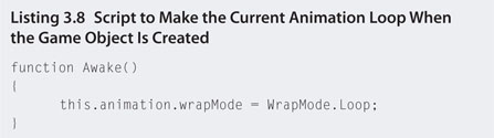
Step 6. Save and play. The model will walk on the spot. The WalkForward animation has a start and an end frame pose that matches. This allows the animation to play over and over again seamlessly. To see what an unmatched animation looks like, set the current animation to WalkIdle and run it again. You will notice a frame jump between the end of one loop and the start of the next.
Step 7. Add a rigidbody and a capsule collider to the model. As shown in Figure 3.9, position the capsule collider so that the model’s feet appear to rest on the ground. For the rigidbody, freeze the x, y, and z axis rotation. This will stop the model from toppling over.
Step 8. Open the animationController.js script and modify as shown in Listing 3.9.

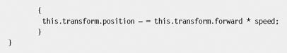
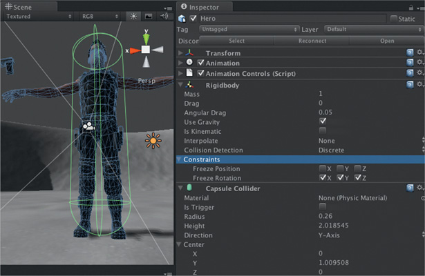
FIG 3.9 A capsule collider around an animated character.
Step 9. Play. The up and down arrow keys will move the character forward and backward. However, the backward animation will look strange as it is still applying the walking forward cycle. If the character seems to be skating across the ground, change the speed until it looks better. If the character is floating a little above the ground, move the capsule collider up a bit so that the feet of the model fall and touch the ground.
Step 10. To add in a forward, backward, and idle animation for the different states of the character, modify animationControls.js to the code in Listing 3.10.
Step 11. Play. The character will have a more natural movement when going backward and will stand still when the arrow keys are not pressed. The only problem now is that the start and end frames of the idle animation do not match well with the forward and backward start and end frames. To overcome this, the idle animation could be

recreated. This would prove quite laborious. A nice thing Unity lets you do is blend animations to give a more seamless transition.
Step 12. Change all the occurrences of Play in the Update function with the function name CrossFade.
Step 13. Play. The character will now transition smoothly between animation states.
Step 14. To make the camera follow the character, move the view around in the scene until you are looking at the character from behind in a position slightly up and to the right as shown in Figure 3.10. With the camera selected in the Hierarchy, select GameObject > Align With View from the main menu. Once you have the camera in a place you would like, drag and drop it in the Hierarchy onto the Hero game object. The camera will become a child object of the model and follow it wherever you move it.
Step 15. To add turning and running to the character, the same format as the existing code is used to test for the left and right arrow keys for turning and the right shift key for running. When turning, the model’s transform is simply rotated. Modify animationControls.js to the code in Listing 3.11.
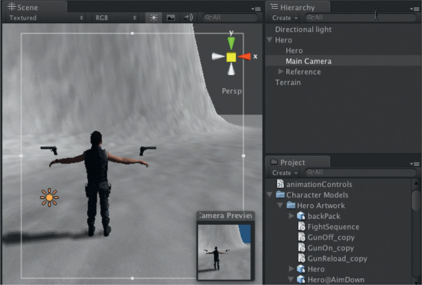
FIG 3.10 Positioning the camera for a third-person view.
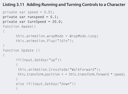

Step 16. Play. The right shift key will make the character run, and the left and right arrows will turn it. Many other animations come with the character. Try mapping these to keys in animationControls.js for yourself.
3.6 Biomechanics
Biomechanics is a field of study that examines the mechanical movement of biological systems such as humans, plants, and animals. It plays an important part in animation describing the way in which natural hierarchical systems such as the human skeleton move. The hierarchy for a skeleton begins at the skull and divides into a number of segments, including arms, legs, hands, and feet that connect to one another by joints. When higher level joints, such as the shoulder, move, any connected lower level segments, such as the hand, move too. In contrast, when a lower level joint or segment moves, such as a finger, any higher level segments, such as the skull, do not move. Aristotle first wrote about biomechanics in De Motu Animalium (On the Movement of Animals).
There are a number of ways a skeletal structure can be specified for animation. The Humanoid Animation Working Group (http://www.h-anim.org) is an international project with the goal of providing a standard profile for a humanoid skeleton so it can be used consistently across a number of applications. A partial view of the standard is illustrated in Figure 3.11. This makes the process of swapping characters in and out of games and virtual environments more streamlined. Imagine being able to take your favorite character from Halo and using it in The Sims. This of course would not work; however, if both games used the same rules of the H-Anim specification it would.
FIG 3.11 A partial view of the H.Anim project’s specifications for a humanoid skeletal hierarchy showing minimal joints.

The premise behind H-Anim and any other skeletal representation is the connection of straight segments and rotatable joints. The way in which these structures move is analyzed by the applied mechanics discipline of kinematics.
Kinematics describes the motion of objects without consideration of the causes leading to the motion. It examines linear and rotational movement with respect to distance, direction, and velocity. These are the very same concepts developed in the previous chapter through the examination of vector mathematics. Kinematics can be examined from two points of view: forward and inverse.
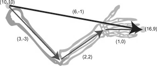
Forward kinematics calculates the final position of the end of an articulated object given the angle and rotation of the joints and the length of the segments. To exemplify, forward kinematics can calculate the position of a character’s hand given the rotation and angles of joints and the length of the bone segments. The hand in this case is what is known in kinematics as the end effector. To solve such a problem, simple vector mathematics is employed. Each bone has a length and direction that are specified as a vector. Adding all the vectors together will give the final destination. As illustrated in Figure 3.12, if the shoulder is positioned at (10,10) with the humerus (upper arm bone) making a vector of (3,-3), the radius and ulna (lower arm bones) making a vector of (2,2), and the hand with a vector of (1,0), the final position of the finger tips will be at (16,9).
Inverse kinematics is used in games to ensure that characters connect with the environment. For example, in The Sims, when a character interacts with an object, the game must ensure that the character is standing in the correct position to pick the object up. Although the bending over and picking up an object is a premade animation, the character still needs to be positioned in the correct location to perform
FIG 3.12 A forward kinematic example with an arm in 2D.
a convincing connection with the object. For that reason, if a Sim is required to pick up a guitar, the character will walk over to the item first and position itself such that when the pickup animation plays it looks as though the object is picked up.
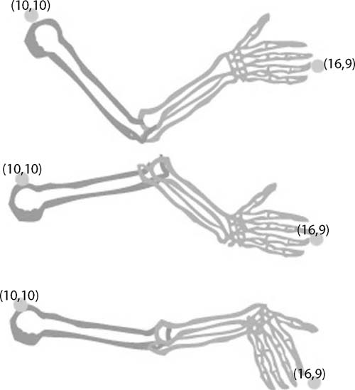
Inverse kinematics is somewhat more complex than forward kinematics. It performs the reverse operation of forward kinematics, asking what the angles of the joints must be to position the end effector at a specific location. For example, if the shoulder is at (10,10), how should the bones in the arm be positioned to place the hand at (16,9)? This is not as simple as it might first appear because, when you think about it, the joints in the arm can make a variety of angles, as shown in Figure 3.13.
Try it for yourself. Grab hold of a doorknob and, keeping your shoulder at the same location in space, see how many different positions you can manipulate your arm into such that your hand stays touching the doorknob. These are just the movements for your arm, which consists of three basic joints and three principal segments. Imagine calculating inverse kinematics for something with 10 or more joints.
Although we consider the shoulder as a single joint, for the purposes of inverse kinematics, it is actually three. If you hold your arm straight out to the side you will be able to raise and lower it (like flapping to fly), move it
FIG 3.13 Three solutions to an inverse kinematic problem.
from side to side (like waving past traffic), and also rotate it (as though your outreached hand is turning a knob). Each distinct movement is called a degree of freedom (DOF). Therefore, the shoulder has three DOFs: two that translate the attached segment and one that rotates it.
![]() Unity Hands On
Unity Hands On
Inverse Kinematics
In this hands-on session you will learn how to implement simple inverse kinematic algorithms to control the angle and direction of a character’s arms and weapon. In this workshop, the mouse will be used to position a target on the terrain. Inverse kinematics will be used to position the character to be aiming at the target.
Step 1. Download Chapter Three/CharacterIK.zip from the Web site. Unzip and open the project in Unity. The scene will contain the animated character from the last workshop.
Step 2. The first thing we are going to do is add something for the character to aim at on the terrain. To do this, the mouse will be used as a pointer. Where the mouse is clicked on the terrain, a target object will appear. This object will be a simple sphere. To achieve this, modify the animationControls script to that in Listing 3.12.
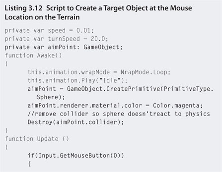

Step 3. Play. A red-colored sphere will appear on the terrain at the mouse location. It will appear to move around if you hold the left mouse button down and move the mouse. In this case the target is a primitive sphere; you could of course add any model you like by instantiating a game object.
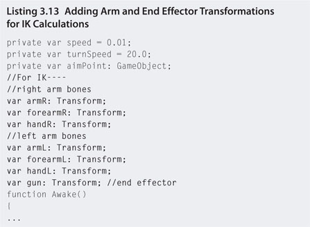
Step 4. Next, the IK calculations need transformations of the bones and the end effector. Include these as variables at the top of the animationControls script as shown in Listing 3.13.
Step 5. Set each of the values for the transformations by locating the script attached to the Hero game object and dragging and dropping the appropriate child objects from the Hero onto the values in the Inspector as shown in Figure 3.14.

FIG 3.14 Attaching model bones to script variables.
Step 6. Before moving the arm bones into position, the end effector (gun) needs to be positioned. As it is going to point at the target, we can use the LookAt() function to change its orientation. The LookAt() function will rotate the object such that the positive z axis (the blue arrow) is pointing toward a target. If you click on the right gun in the Scene, you will notice that the blue axis is not aligned with the barrel of the gun. In this case, if you just use LookAt() it will orientate the side of the gun to face the target. This means after using LookAt() we have to make a 90° adjustment to get the barrel of the gun pointing at the target. To achieve this, add the new function in Listing 3.14 to the end of animationControls.js.


Step 7. Play. The gun in the character’s hand will orientate to always face the red sphere as the mouse moves it around the game environment. Any manual modification to the character’s animation, such as inverse kinematics, must occur in the LateUpdate() function—the reason being that normal animations for the character will still be running and are assigned to the model before LateUpdate(). If changes to the model occur before this, baked animations will simply replace any changes that you make with code.
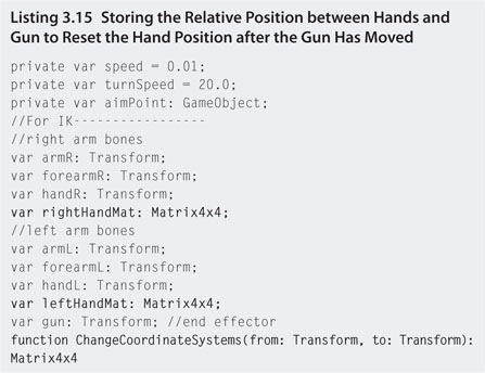
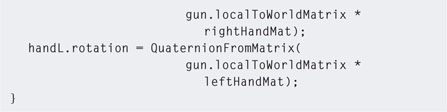
Step 8. Because the character’s hands are grabbing the gun, it makes sense that they move as the gun does. To do this, we need to record the relative location of the hands before the gun moves and then use this to line up the hands with the gun after the gun has moved. This requires working with 4 × 4 matrices and quaternions. The following changes you need to make to the animationControls script, shown in Listing 3.15, have been designed to be as painless as possible.

Step 9. Play. The hands will now orientate with the gun. They don’t change position, just rotation, and therefore are a little inaccurate when the gun is in some orientations. So far we haven’t used any inverse kinematic calculations. They start now. The objective will be to rotate the shoulder, elbow, and wrist joint to suit the gun orientation.
Step 10. Download Chapter Three/IKplugins.zip from the Web site. It contains two C# code files from the Locomotion project for calculating inverse kinematics. For more on this, see http://www.unity3d.com/support/resources/unity-extensions/locomotion-ik.html. Unzip these files. Create a folder in the Project called Plugins and place the IK1JointAnalytic.cs and IKSolver.cs in it.
Step 11. Now modify animationController.js to use the inverse kinematics code to rotate the shoulders, elbows, and wrists as shown in Listing 3.16.

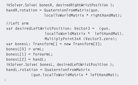
Step 12. Play. Drag the target sphere around in front of the character and note how the shoulders, elbows, and wrists bend to accommodate the orientation of the gun. The ikSolver.Solve() function does this by taking all the bones and the desired location of the end effector and calculating the best angles. Some angles are obviously undesirable, such as if the target goes behind the character. When this occurs, other techniques, such as turning the entire character around or changing her pose, are desirable.
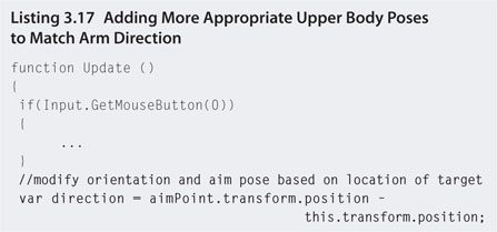
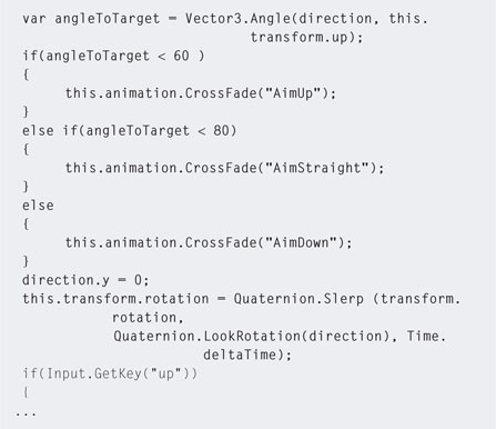
Step 13. To end this workshop, we will add in some other animations based on the angle to the target such that when it is up high the AimUp animation will be used and when low the AimDown animation will be set. The character will also turn around automatically to face the target location. This requires a small change to the Update() function of animationController, as shown in Listing 3.17.
Step 14. Play. Note how the character turns around and the animations change to better suit the height of the target.
![]() Research
Research
Inverse Kinematics
For further in-depth examination of inverse kinematic systems in Unity, download the locomotion project available from http://www.unity3d.com/support/resources/unity-extensions/locomotion-ik.html.
3.7 Animation Management
In the preceding examples of 3D animations, character action sequences were split into segments. In the case of 2D sprites, only one sequence was given (walking); in the 3D examples, each action was contained in its own separate file.
It’s not always the case that animations come to game developers in this way. If you were to download a fully animated character from a site such as TurboSquid, the character may come as a single file containing any number of animation sequences. In the case of 2D sprites, it is not uncommon to find all the action sequences for one character in a single texture atlas.
3.7.1 Single 2D Sprite Actions
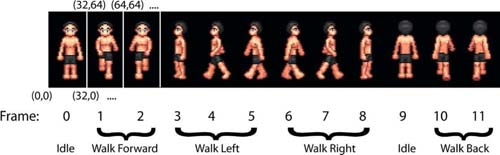
As we’ve seen, a texture atlas is a convenient and optimizing way to keep sprites. More often than not, all the animations for a single character are kept in a texture atlas. This requires pixel management on the part of the programmer to ensure that the correct part of the texture is displayed at the right time. Figure 3.15 shows a texture atlas with several idle and walking animation frames. Although it is not strictly necessary to have the frames belonging to the same animation next to each other in the texture, it makes it monumentally easier to program if they are in sequence and packed together. It’s also easier if each frame is the same size. In the image shown, each frame is 32 × 64.
Individual animations are specified with a starting frame and a number of frames; for example, the walk left animation starts at frame 3 and is three frames in length. By knowing the fixed width for a frame, the exact pixel value for the start of an animation sequence can be calculated. In this case, the walk left animation begins at frame 3, and therefore the starting x pixel location would be 3 × 32 = 96.
FIG 3.15 Joined frames for four separate animations. (Sprite art thanks to Dezire Soft at http://www.touchofdeathforums.com/smf/index.php/topic,26460.0.html.)
![]() Unity Specifics
Unity Specifics
If the sprite atlas does not have power of two dimensions, Unity will squash and stretch it to make it so. This will produce an undesirable effect with the frame locations. To correct this, select the texture in the Project and in the Inspector set the Texture Type to Advanced and the Non Power of 2 to None, as shown in Figure 3.16.

FIG 3.16
![]() Unity Hands On
Unity Hands On
Managing Animated Sprite Sequences
Step 1. Download Chapter Three/SpriteManager.zip from the Web site. Open the project in Unity and open the spritemanage scene. You will find a single basic plane with the SpriteManagement.js script attached. The script will be empty. The plane will have a sprite texture atlas on it.
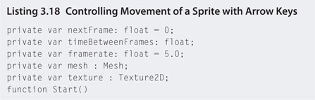
Step 2. Open SpriteManagement.js in the script editor and add the code in Listing 3.18.

Step 3. Play. The sprite will be moveable with the arrow keys. The image on the sprite will be blurred, as it is not yet set up correctly.
Step 4. Next we need to create some simple data structures to store the frame size as well as the starting frames and length for each animation sequence. A neat way to do this is to create simple class structures to store the information. When named with meaningful variable names, the editor displays a nice way to edit the information. Modify SpriteManagment.js by adding the code in Listing 3.19 to the very top of the script.
Step 5. Select the Plane child object of basicPlane in the Hierarchy. In the Inspector, locate the attached SpriteManager script as shown in Figure 3.17. Note how the variables from the classes in the script are displayed in the Inspector. This makes them easy to recognize and edit. This could have been achieved easily using Vector2 data types; however, it would have been messier. Enter the values into the Inspector for the sprite dimensions and animation sequences as shown in Figure 3.17.
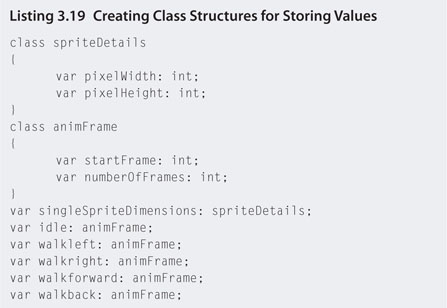

FIG 3.17 Variables contained in class structures displayed in the Inspector.
Step 6. Next you need to align the sprite walking direction with the animations and use the pixel values entered into the Inspector to display the correct animation sequence. To do this, a UV mapping code similar to that used in previous examples will be used. When a different arrow key is pressed, the animation sequence being displayed will change. Modify SpriteManager.js as shown in Listing 3.20.

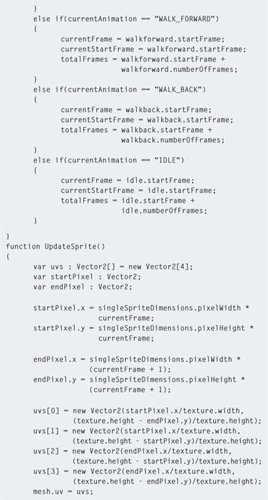

Step 7. Play. The sprite will now be animated with the correct sequence of frames depending on the direction it is moving.
3.7.2 Single-Filed 3D Animations
Original 3D FPS games such as Quake 3 Arena (Q3A) use a single track of 3D animation that defines many separate animations in the same way as an animated sprite texture atlas. Animations for a character in Q3A, a Quakebot, for example, are played from specified frames—some looped and some not. To create a series of animations for a Quake character, a number of different animations need to be specified and then glued together. For example, the running animation might go from frame 30 to frame 45, and the swimming animation might go from frame 46 to frame 57.
Animations in Q3A must be set up in a specific order. The order and length of the animations are displayed in Table 3.1.
| TABLE 3.1 Order and frame size of animations used in Q3Aa | |||
| Animation | Length (in frames) | Description | |
| Category: Full body | |||
| BOTH_DEATH1 | ~30 | Full body animation | |
| BOTH_DEAD1 | ~1 | Death scenes and final | |
| BOTH_DEATH2 | ~30 | Death poses | |
| BOTH_DEAD2 | ~1 | ||
| BOTH_DEATH3 | ~30 | ||
| BOTH_DEAD3 | ~1 | ||
| Category: Upper body | |||
| TORSO_GESTURE | ~45 | e.g., taunting | |
| TORSO_ATTACK | 6* | Attack other player | |
| TORSO_ATTACK2 | 6* | Attack other player | |
| TORSO_DROP | 5* | Drop arms as to change weapon | |
| TORSO_RAISE | 4* | Lift up new weapon | |
| TORSO_STAND | 1* | Idle pose for upper body | |
| TORSO_STAND2 | 1* | Idle pose for upper body | |
| Category: Lower body | |||
| LEGS_WALKCR | ~10 | Crouched while walking forward | |
| LEGS_WALK | ~15 | Walking forward | |
| LEGS_RUN | ~12 | Running forward | |
| LEGS_BACK | ~10 | Back pedaling | |
| LEGS_SWIM | ~10 | Swimming | |
| LEGS_JUMP | ~10 | Jumping up forward | |
| LEGS_LAND | ~6 | Landing after jump | |
| LEGS_JUMPB | ~10 | Jumping up backward | |
| LEGS_LANDB | ~6 | Landing after backward jump | |
| LEGS_IDLE | ~10 | Idle pose for lower body | |
| LEGS_IDLECR | ~10 | Crouched idle pose for lower body | |
| LEGS_TURN | ~8 | Turning on the spot | |
| aAll animation lengths are approximations with the exception of those indicated by an asterisk, which need to be exact. | |||
As shown in Table 3.1, upper and lower animations are separate with the exception of death scenes. Therefore, movement of the upper body is independent of the lower body. This allows for different animation effects by combining differing animation parts. However, this can be a slight problem when two unrelated animations are combined; for example, an upper TORSO_ATTACK combined with a LEGS_SWIM would look strange. Although this system of animation has the drawback of creating inappropriate movements, it does provide for an overall greater number of animations.
Because many of the animation sequences do not have a defined length, an animation configuration file needs to be generated for the QA3 game engine so that it can locate the correct animation progressions. The configuration file is called animation.cfg and is loaded into the QA3 engine with the appropriate model. The configuration file contains information on the first frame of the sequence, the length, in frames, of the sequence, the number of times to loop the animation, and how fast to play it. The file contains this information for each animation sequence in the order shown in Table 3.2.
TABLE 3.2 A partial animation configuration file |
||||
| Animation | First frame | Number of frames | Times to loop | Frames per second |
| BOTH_DEATH1 | 0 | 30 | 0 | 25 |
| BOTH_DEAD1 | 29 | 1 | 0 | 25 |
| TORSO_GESTURE | 90 | 40 | 0 | 15 |
| TORSO_ATTACK | 130 | 6 | 0 | 15 |
A model is defined as three separate parts: head, torso, and legs. Each part of the model is linked internally by what is known as a tag. Tags control the locations at which the parts of the model are connected. Because each part is dealt with separately, the tags essentially join them together. There are three principal tags in a QA3 model: tag_head (which joins the head to the torso), tag_torso (which joins the upper body to the lower body), and tag_weapon (which provides a location to attach the weapon model). For games such as QA3 that allow players to modify and create their own character models, having a standard format such as this is crucial in ensuring that the models are animated and rendered consistently.
![]() Unity Specifics
Unity Specifics
Single File, Multiple Animations
Unity supports model files that have all animations in the same file. Note that not all 3D model formats store animations; for example, .3ds do not, but .fbx do. When the model is imported into the Project, selecting it will bring up the import settings in the Inspector. An example is shown of the Lerpz character available from the Unity Web site in Figure 3.18.
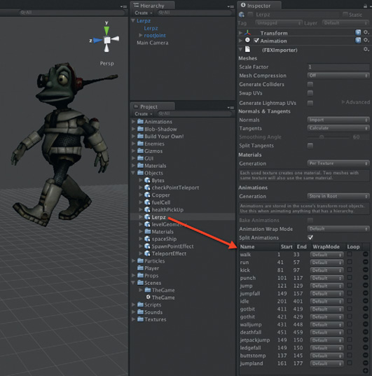
FIG 3.18 An animated FBX file in Unity with animation settings shown in the Inspector.
By specifying a name and the start and end frames for each specific animation sequence, Unity can divide a single file up for easy multiple animation use. For more details on settings in the Inspector, visit http://www.unity3d.com/support/documentation/Manual/Animations.html.
![]() Unity Hands On
Unity Hands On
Managing Multiple 3D Animations
Step 1. Download Chapter Three/Sequenced3D.zip from the Web site and open the SingleAnimFile scene. In it you will find the Lerpz model. If you play, at this point, the model will play through all the animations in the file as they have not been specified individually in the import settings.
Step 2. Select the Lerpz model in the Project. In the Inspector locate the individual animation section of the FBX Importer component.
Step 3. Add two animations as shown in Figure 3.19. Add a walk animation with starting frame 1 and ending frame 33 and a jump animation with starting frame 121 and ending frame 129. Click the Apply button at the bottom of the Inspector view.

FIG 3.19 Adding two animations to the Lerpz character.
Step 4. Create a JavaScript file called controls.js and open with the script editor. Add the code shown in Listing 3.21.
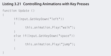
Step 5. Play. The walk animation will play when the left arrow key is down, and the jump animation will play when the space is pressed. The issue now is that the animations only play once; for example, when the left arrow key is pressed the walk animation plays and then stops. To fix this, add the code in Listing 3.22 to the very top of the controls.js file.
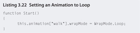
Step 6. Play. The walk animation will now loop. It will only stop when the space bar is pressed for the jump animation.
Step 7. To make the model go into an idle mode when no key is pressed, you need to add an idle animation. To do this, select the model in Project and add an animation called idle with a start frame of 201 and an end frame of 401. Click the Apply button.
Step 8. The idle animation won’t be added automatically to the model in the scene. Therefore, select the Lerpz object in the Hierarchy and locate the Animation component in the Inspector. Change the number of animations from 2 to 3. Set the third animation to idle.
Step 9. Edit controls.js to reflect the code in Listing 3.23.

Step 10. Play. The CrossFadeQueued() function sets up an animation to play after currently playing animations finish. It also fades between animations, which, in this case, allows for a smooth transition between jump and idle.
3.7.3 Blending
While cross fading animations allows for one model posture to smoothly
Animation blending allows for different parts of different animations to be combined.
![]() Unity Hands On
Unity Hands On
Animation Management
Step 1. Download Chapter Three/CharacterAnimManager.zip from the Web site. Unzip and open the project in Unity. Open the animationManagement scene and play. The WASD and arrow keys can be used to move the character around the environment.
Step 2. Open the AnimationManager.js file in the script editor.
Step 3. Note the use of the Input.GetAxis() function. It is a clean way to get the character movement from typical game control mappings. For example, using Input.GetKeyDown() for all the different keys to move forward and backward would be many more lines of code than the two given here.
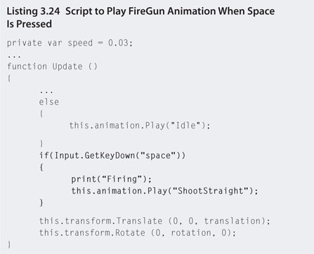
Step 4. The current version of the code allows the character to walk around the environment. Let’s add some code to fire the character’s gun. Add the lines shown in Listing 3.24.
Step 5. Play. It appears as though nothing happens when the space bar is pressed. However, note that “Firing” is being printed in the console, which proves that the if statement is being executed. If you press the space bar a bunch of times and watch the character closely you may see it flinch. So what is happening? The ShootStraight animation starts to run, but before many or any frames play, the Update() function runs again; if the character is not moving, the animation gets set to Idle before ShootStraight has finished playing. This is a common issue in managing animations.
Step 6. To fix this issue in the past, a programmer would have to write code to test if one animation has finished playing before another starts. This can still be done; however, in this case, Unity provides a very neat way for giving priority to animations—layers. Each animation can be assigned a layer. Animations in higher level layers have a higher priority, and lower level animations cannot interrupt their frames. Modify the Start() function of animationManagement script to that shown in Listing 3.25.
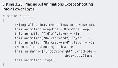
Step 7. This new code will place the idle and walking animations in layer -1. By default, all animations are in layer 0. This means the shooting animation will remain in 0 and be given priority over those in -1. In addition, animations in layer -1 are cyclic and therefore set to loop. We don’t want the shooting animation to loop; therefore, it is set to clamp, which plays it once and stops. Because the shooting animation is in a higher layer, when it is set to play, it becomes visible on the screen while the other animations take a back seat. When the shooting animation reaches the end and stops (because it is not set to loop), animations in the next lower layer can play. In this case it will be the idle and walk cycles. Press play to see this in action.
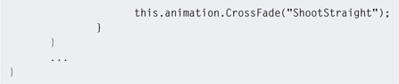
Step 8. Note that when now shooting, the entire shoot animation plays; however, it ends abruptly as the shoot animation finishes and the character jumps back into the idle animation. This can be fixed by blending the animations together to give a smoother transition. Instead of using the Play() function, CrossFade() is used to blend the current animation with a new one. Modify your code with the changes in Listing 3.26.
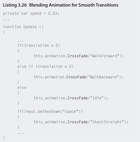
Step 9. Play. Note how the transition between animation states is smoother.
Step 10. The last issue to take care of is the shooting while moving. Currently, if the character is moving and the space bar is pressed, the character will play the shoot animation and slide along the ground. You can deal with this in two ways. Stop the character moving and shooting at the same time or include an animation in which the character is moving and shooting simultaneously. Instead of creating an entirely new animation, you can blend the top of the shooting animation with the bottom of the walking animation with code. Add the code in Listing 3.27 to your script.

Step 11. Play. A new animation clip will be created that uses the ShootStraight animation as a basis and mixes the transformations for the gun and spine animations from any other animation playing in another layer at the same time. In this case it is restricted to WalkForward.
3.8 Secondary Animation
Secondary animation refers to movement that occurs as a result of primary animation. For example, when a character walks, in response to the movement, his hair might move and his muscles ripple. If a character shoots a weapon you’d expect a recoil action. Secondary animation is caused by the law of physics, which dictates that every action has an equal and opposite reaction. Without the extra animation a character can appear static and unrealistic.
Depending on the level of secondary animation, it can be processor intensive and not feasible in a real-time game environment. The avatars used in Quake Arena and Unreal Tournament are very simple with tight-fitting clothing and close-cut hair. This is not because the artist couldn’t be bothered or at the time didn’t have the technology to create highly realistic models—it is simply because animating all the extra elements with secondary animation was not feasible on the hardware available at the time these games were released. Even today, hair and cloth in 3D real-time environments are limited. A very nice example of the secondary animation of cloth can be seen in Assassin’s Creed. The cloak and ropes of the main character move in response to the character’s movements and the wind.
As hardware capabilities increase so will the quantity and quality of secondary animation.
Other animations that could also be considered secondary to the main character are those that bring the environment to life, for example, trees swaying in the breeze, water running in a river, other characters walking down the street, or even the main character’s own clothing, such as a cape.
Adding Secondary Animations
Step 1. Download Chapter Three/SecondaryAnimation.zip from the Web site. Unzip and open with Unity. Open the secondaryAnim scene. The scene is the final product from the previous workshop. Double-click on Hero in the Hierarchy to center the scene on the character.
Step 2. From the main menu, select GameObject > Create Other > Cloth. A large plane will be added to the scene. Drag the Interactive Cloth object in the Hierarchy onto the top-level Hero object. The Interactive Cloth will become a child object of Hero.
Step 3. Download Chapter Three/Cape.blend from the Web site and drag and drop the file into the Project.
Step 4. Locate the cape model in the Project and click on the small arrow next to it to expand. Next, select the Interactive Cloth from the Hierarchy and locate the Interactive Cloth component in the Inspector. Drag the Cape New mesh in the Project onto the Mesh variable in the Inspector as shown in Figure 3.20.
FIG 3.20 Creating a cape using a 3D cape model and an interactive cloth object.
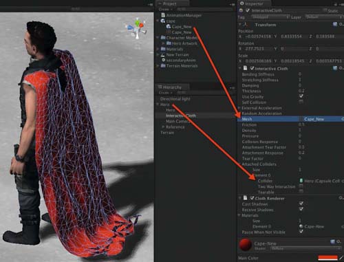
Step 5. At this point the cloth cape object will be immensely huge. Double-click on the Interactive Cloth object in the Hierarchy to position the camera in the scene on its location. You will now need to scale, rotate, and transform the cape such that it is in the same position relative to the character shown in Figure 3.20. if you haven’t moved the character, the correct cape transforms are also shown in Figure 3.20.
Step 6. With the cape in position, select the Interactive Cloth and add one Attached Collider in the Inspector. Drag the main Hero object from the Hierarchy onto the Collider variable as shown in Figure 3.20. The cape must intersect with the character’s collider in order for it to stick to it. This is the same principle used for hanging up the curtain in the warehouse of Chapter Two.
Step 7. Play. The cape will be attached to the character’s shoulders and move when he moves.
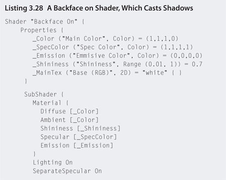
Step 8. A final touch would be to add a shader with backface culling turned off so that the cape is visible from both sides. The code for this is similar to that used for the curtain in Chapter Two. However, one small detail needs to be added to ensure that the cape casts a shadow. Create a new shader in the Project and call it BackfaceOn. Open the file in script editor by double-clicking on it and replace the code with ALL of that in Listing 3.28. The part shown in bold is the line needed for shadows that would have been missing from the curtain shader in Chapter Two.

Step 9. Play. The character now has a fully fledged flowing cape complete with secondary animation. The final character is shown in Figure 3.21.
![]() Note
Note
The cape model used in the previous workshop was a freely available model from Turbosquid. The original file had too many polygons to be used for cloth rendering. It slowed down the processor such that the application ran at a snail’s pace. To reduce the polycount, the cape model was opened with Blender, and with the object selected and placed in Edit mode, the Poly Reducer was used as shown in Figure 3.22. Running this script several times reduced the cape down to fewer than 2000 polygons.

FIG 3.21 The character complete with cloth cape.

FIG 3.22 The polygon reduction tool in Blender.
3.9 Summary
This chapter examined 2D and 3D animation principles and techniques. As moving and animated objects are key elements in games, understanding how a game engine manages and manipulates these assets is key to including them effectively in games.