
CHAPTER 2

Real-World Mechanics
The player's primary logic operates within the known possibilities of physics. Keep in mind gravity, weight, mass, density, force, buoyancy, elasticity, etc. Use this as the starting point, but do not be limited by it.
Matt Allmer
2.1 Introduction
An understanding of motion and the driving forces thereof is crucial in understanding games. Most objects in games move. That is what makes them dynamic. Whether it be a 2D character such as the original Mario or a fully fledged 3D character such as Halo's Master Chief, they and their game environments are in constant motion.
To grasp the concept of motion, especially with respect to computer games, a development of foundation knowledge in vector mathematics is required. Vectors are used extensively in game development for describing not only positions, speed, acceleration, and direction but also within 3D models to specify UV texturing, lighting properties, and other special effects.
Before leaping into the use of vectors in games for defining motion, a crash course in essential vector mathematics for game environments is presented in the next section.
2.2 Principles of Vectors
In Chapter One, a vector was introduced as a line with a length (magnitude) and a direction (indicated by an arrow). Vectors can be used to represent measurements such as displacement, velocity, and acceleration. In 2D, a vector has x and y coordinates. In 3D, it has x, y, and z coordinates. In pure mathematics, a vector is not a point in space, but a set of changing coordinate instructions. It can be likened to the instructions on a fictional pirate's treasure map, for example, take three steps to the west and seven steps to the south. As shown in Figure 2.1, the instructions three steps to the west could be interpreted as the vector (3,0), meaning move 3 in the positive x direction and nothing in the y direction. The instructions move seven steps to the south become the vector (0, −7), meaning move only 7 in a negative y direction.
To determine the final location, vector x and y values are added to the starting point x and y values. For example, in Figure 2.1, the pirate ship lands at (4,8) and moving (3,0) will place them at (4 + 3, 8 + 0) = (7,8). Then moving (0,−7) will put them at (7 + 0,8 − 7) = (7,1). They can also take a shortcut by going directly in a straight line to the treasure. In this case, the two instruction vectors (3,0) and (0,−7) are added together and become (3,−7). By taking the starting location and adding this new vector, they will end up in the same location [i.e., (4 + 3,8 − 7) = (7,1)].
FIG 2.1 A pirate's treasure map illustrating the use of vectors.
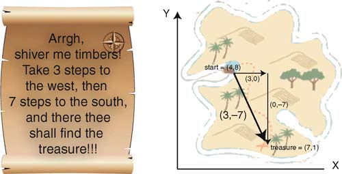
To travel from the treasure back to the ship, the pirates can follow the same line but in the opposite direction. This is achieved by flipping the vector such that all coordinate values are multiplied by −1. In this case, to get back to the ship they follow the vector (−3,7).
It might also be useful for the pirates to know how far the treasure is from the ship. The length of a vector, v, called its magnitude and written |v|, is found using Pythagoras' theorem shown in Equation (2.1).
![]()
For the pirates, it means that their journey is a length of 7.62 (kilometers, if the units being used are kilometers), that is, ![]() .
.
Sometimes it is necessary to scale a vector so that it has a length equal to 1. The process of scaling the length is called normalizing, and the resultant vector, which still points in the same direction, is called a unit vector. To find the unit vector, each coordinate of the vector is divided by the vector's length. In the case of the pirate's journey, this would equate to (3/7.62, −7/7.62) = (0.39,−0.92). If the pirate takes 0.39 steps to the west and 0.92 steps to the south, he will end up a distance of 1 from his starting position, right on the original vector, as shown in Figure 2.2. As can be seen, the vectors (3,−7) and (0.39,−0.92) are parallel and the magnitude of (0.39,−0.92) is 1. The unit
FIG 2.2 A normalized vector has a length of 1.
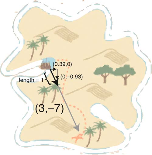
vectors for north, south, east, and west as they would be overlaid on a map of the earth1 are (0,1), (0,−1), (−1,0), and (1,0).
Two further important calculations can be performed with vectors. These are the dot product and the cross product. The use of these in computer graphics and games programming will become overwhelmingly clear later. Among other things, the dot product can be used to calculate the angle between two vectors and the cross product can be used to determine the direction.
The dot product is calculated by taking two vectors, v and w, and multiplying their respective coordinates together and then adding them. The dot product results in a single value. It can be calculated using Equation (2.2).
Given the vectors v = (1,0) and w = (3,−7), the direction the pirate is facing and the direction to the treasure (shown in Figure 2.3), the dot product will be 1 × 3 + 0 × −7 = 3.
But what does this mean? The most useful application of the dot product is working out the angle between two vectors. In a moment we will work out the actual value of the angle, but for now by just knowing the value of the dot product you can determine how the vectors sit in relation to each other. If the dot product is greater than zero, the vectors are less than 90° apart; if the dot product equals zero, then they are at right angles (perpendicular); and if the dot product is less than zero, then they are more than 90° apart.
To find out the exact angle the pirate must turn to face the treasure, the arccosine of the dot product of the unit vectors is calculated. The unit vector for (3,−7) is (0.39,−0.92) as already established and (1,0) is already a unit vector. This result for the angle between the vectors is therefore:
= arcos((1,0).(0.39,0.92))
= arcos((1 × 0.39) + (0 × 0.92))
= arcos(0.39)
= 67°
You can always check the result of your calculation by looking at a plot of the vectors and measuring them with a protractor. In this case, by taking a visual estimate, the angle is larger than 45 and less than 90; therefore, the calculation appears to be correct.
Now imagine the pirate is told to turn 67° and walk for 7.62 kilometers to get to the treasure. Which way does she turn? The image in Figure 2.3 shows that a decision needs to be made as whether to turn to the right or the left.
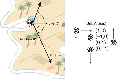
FIG 2.3 A pirate facing (1,0) and the vector to the treasure.
In computer graphics, a positive value for an angle always indicates an anticlockwise turn. An anticlockwise turn in this case would have the pirate facing away from the treasure. When calculating the angle between vectors using the dot product, the angle is always positive. Therefore, you need another method to determine the turn direction. This is where the cross product comes into play.
The cross product of two vectors results in another vector. The resulting vector is perpendicular (at 90°) to both the initial vectors. This sounds odd working in 2D as a vector at right angles to two vectors in 2D would come right out of the page. For this reason, the cross product is only defined for 3D. The formula to work out the cross product is a little obtuse and requires further knowledge of vector mathematics, but we will try to make it as painless as possible.
The cross product of two vectors, v and w, denoted v × w is shown in Equation (2.3):
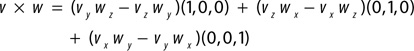 (2.3)
(2.3)The equation is defined in terms of standard 3D unit vectors. These vectors are three unit length vectors orientated in the directions of the x, y, and z axes. If you examine Equation (2.3) you will notice that there are three parts added together. The first part determines the value of the x coordinate of the vector, as the unit vector (1,0,0) only has a value for the x coordinate. The same occurs in the other two parts for the y and z coordinates.
To find the cross product of two 2D vectors, the vectors first need to be converted into 3D coordinates. This is as easy as adding a zero z value. For example, v = (1,0) will become v = (1,0,0) and w = (0.39,−0.92) will become w = (0.39,−0.92,0). The value of v × w would equate to (0 × 0 – 0 × −0.92)(1,0,0) + (0 × 0.39 – 1 × 0)(0,1,0) + (1 × −0.92 – 0 × 0.39)(0,0,1) = 0(1,0,0) + 0(0,1,0) + − 0.92(0,0,1) = (0,0,0) + (0,0,0) + (0,0,− 0.92) = (0,0,− 0.92). This vector only has a z coordinate and therefore is directed along the z axis. It is therefore coming out of the page.
An interesting thing to note about the cross product is that if the order of the equation is reversed, the resulting vector is different. w × v would equal (0,0,0.92) (check this out!), which is a vector the same length as the one produced by v × w, but traveling in the exact opposite direction. This differs from the calculation of the dot product that yields the same answer no matter what the order of the vectors.
How does this help the pirate determine the direction in which to turn?
If he starts by facing in the direction of v and wishes to turn to face w, we can calculate v × w. If we examine Figure 2.3 it can be seen that w would be on the pirate's right and therefore would require a clockwise turn. We know from the previous example that a clockwise turn between two vectors produces a cross product result with a negative z value. The opposite is true for an anticlockwise turn. Therefore, we can say that if z is positive it means an anticlockwise turn and if z is negative, a clockwise turn.
The pirate now knows to turn to his right 67° clockwise and travel 7.62 kilometers in a straight line to reach the treasure.
This may all seem obvious by looking at the map. However, objects in a game environment that have no visual point of reference, such as artificially controlled bots or vehicles, require these very calculations in order to move around successfully in a virtual environment.
![]() Unity Hands OnSpecifics
Unity Hands OnSpecifics
Vectors
Every object in Unity has a number of vectors associated with it. A Game Object's transform component has three: position, rotation, and scale. Figure 2.4 shows the layout of a typical game environment with a car model as a game object. Usually, in 3D, the y axis represents up, the x axis to the side, and the z axis forward. Both the environment and all game objects have their own transforms. The axes are displayed in the Scene as red, green, and blue arrowed lines, as shown in Figure 2.4. The y/up axis is green, the x/side axis is red, and the z/forward axis is blue.
The environment has its own axes, and the orientation is set by the way you change the scene around to look at different objects. In the Game,
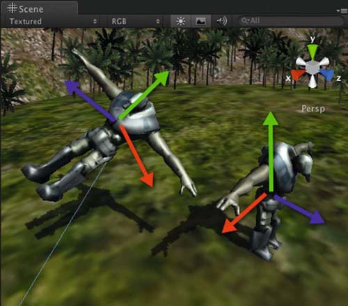
FIG 2.4 Vectors in the Unity 3D environment.
the orientation is dependent on the camera's orientation. Each game object has its own local orientation depicted by a set of axes appearing in the Scene when the object is selected. So while the y axis for the world may be vertical in a scene, it could be horizontal locally for an object that is lying down.
In Unity, there are two vector classes: Vector2 and Vector3. A game object's position, rotation, and scale values are stored as Vector3. Vector2 is useful for storing 2D vector information.
A game object also has a vector for each of its x, y, and z axes: Vector3.left, Vector3.up, and Vector3.forward, respectively. These are useful for moving an object along its axes without needing to know its orientation.
![]() On the Web Site
On the Web Site
Vector2 and Vector3 Class Definitions
Detailed information about the Unity vector classes can be found in the Script Reference here: http://unity3d.com/support/documentation/ScriptReference/Vector2.html and http://unity3d.com/support/documentation/ScriptReference/Vector3.html.
2.3 Defining 2D and 3D Space
Whether it is in 2D or 3D space the principles of vectors are applied in the same way. As we explored with vectors, the difference between a 2D coordinate and a 3D coordinate is just another value. In 3D game engines, such as Unity, 2D games are created by ignoring one of the axes. In the rocket ship application shown later in this chapter, all game objects are positioned in the same plane, having a y position value initially set to 0. All movements thereafter only move and rotate the objects in x and y. This is the same principle as moving objects around on a flat tabletop. In the rocket ship game, the camera is positioned directly above the game objects and perspective is removed to give the illusion of a truly 2D world.
The camera in a game is a critical component as it presents the action to the player. It is literally the lens through which the game world is perceived. Understanding how the camera moves and how to set what it looks at is essential knowledge.
2.3.1 Cameras
The camera in a game defines the visible area on the screen. In addition to defining the height and width of the view, the camera also sets the depth of what can be seen. The entire space visible by a camera is called the view volume. If an object is not inside the view volume, it is not drawn on the screen. The shape of the view volume can be set to orthographic or perspective. Both views are constructed from an eye position (representing the viewers' location), a near clipping plane, the screen, and a far clipping plane.
An orthographic camera projects all points of 3D objects between the clipping planes in parallel onto a screen plane, as shown in Figure 2.5. The screen plane is the view the player ends up seeing. The viewing volume of an orthographic camera is the shape of a rectangular prism.
A perspective camera projects all points of 3D objects between the clipping planes back to the eye, as shown in Figure 2.6. The near clipping plane becomes the screen. The viewing volume of a perspective camera is called the frustum as it takes on the volume of a pyramid with the top cut off. The eye is located at the apex of the pyramid.
The result of using a perspective and orthographic camera on the same scene in Unity is illustrated in Figure 2.7. A perspective camera is used in Figure 2.7a. The way in which perspective projections best show depth is evident from the line of buildings getting smaller as they disappear into the distance. This is not the case for the orthographic camera shown in Figure 2.7b. Depth can only be determined by which objects are drawn in front. The buildings appear to be flattened with no size difference between buildings in the distance. Figures 2.7c and 2.7d illustrate the way in how the camera view volume is displayed in Unity's Editor Scene. If an object is not inside the view volume in the Scene, it will not appear on the screen in the Game.
FIG 2.5 Orthographic projection.
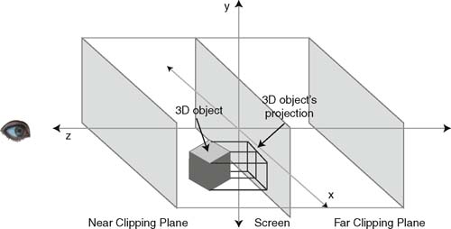
FIG 2.6 Perspective projection.
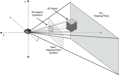

FIG 2.7 A 3D scene in Unity using a perspective camera (a) and an orthographic camera (b). (c) The perspective camera's frustum as displayed in the Unity Scene. (d) The orthographic camera's frustum as displayed in the Unity Scene.
![]() Unity Specifics
Unity Specifics
Cameras
When you first create a new project in Unity it will come with a Main Camera in the Hierarchy. Selecting a camera reveals the settings in the Inspector. Examples for orthographic and perspective cameras are shown in Figures 2.8a and 2.8b, respectively.
While setting the camera values for the near and far planes in the Inspector, the resulting frustum can be watched in the Scene. To change the width and height of the viewing volume, the field of view (FOV) is modified for a perspective camera. The greater the field of view, the more the player will be able to see around his immediate area. To get a feel for the field of view, hold your arms out to the side and look straight ahead as if to make a cross figure with your body. Slowly bring your arms around to your front until you can just see both hands out of the corners of your eyes (while looking straight ahead). When your hands come into
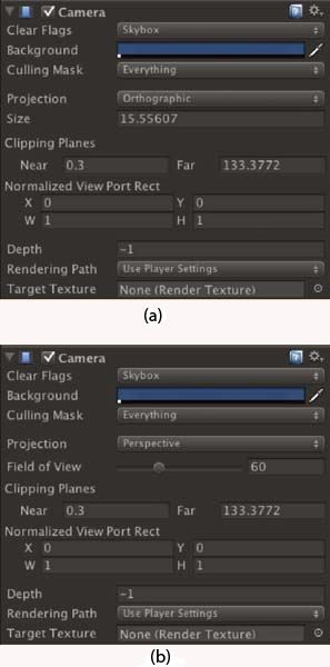
FIG 2.8 Settings for the Unity camera.
your peripheral vision, the angle your arms make is your field of view. The average human forward-facing field of view is close to 180° while some birds are capable of almost 360°.
The complementary field of view for the orthogonal camera in Unity is set by the size property.
Getting Comfortable behind the Camera
Step 1. Download Chapter Two/CameraPlay.zip from the Web site, unzip, and open in Unity. In the Project, double-click on street of the Scenes folder to open the scene. The Scene will appear with a row of medieval houses on a terrain.
Step 2. Modify the window tabs if necessary to enable viewing of the Game and Scene at the same time. Select Main Camera from the Hierarchy. Zoom in or out in the Scene so that the camera and its frustum are in full view. If you can't find the camera, double-click on it in the Hierarchy to bring it into the center of the Scene.
![]() Note
Note
To set the Game view camera to look at the environment from the same location set in the Scene, select the Main Camera in the Hierarchy and GameObject > Align with View from the main menu. This repositions the camera to be looking at the scene from your point of view.
To move independently around in the Scene, leaving the camera where it is, hold down “Q” and drag the mouse to pan and hold down “ALT” and drag the mouse to rotate.
Step 3. Locate the Camera component for it in the Inspector. Find the Field of View slider. Move the slider forward and back to change the viewing angle. Take note how the frustum is affected in the Scene and the resulting Game view.
Step 4. Set the Field of View to 60°. This is a popular setting for the FOV in many games. This setting is half the total viewing angle. In this case it gives you 120°.
Step 5. Change the Far clipping plane to 90. Note that half of the background trees are missing in the Game. This is because they are now beyond the far plane and outside the frustum. The background color you see is set by the Background property in the camera settings.
Step 6. To watch the effect of changing the far plane distance continually, place the mouse over the word Far, hold down the right mouse button, and drag it left and right to decrease and increase the value in the Far box. This method can be used for changing the values of most properties in the Unity Editor.
Step 7. Now, do the same for the Near clipping plane and observe how the view in the Game is modified.
Step 8. Change the camera to Orthographic by changing the Projection property of the Camera component. Try modifying the size property to see how it affects the Game view.
Step 9. Change the camera back to a perspective projection. Set the FOV to 60 and the Near and Far planes to 1 and 200, respectively.
Step 10. Create a sphere game object and position it at (620,15,715).
Step 11. Select GameObject > Create Other > Camera from the main menu. Rename it to SphereCam. This camera will become the viewing camera automatically.
Step 12. Locate the Depth property in the SphereCam's Camera component. If this property is larger than the depth for the Main Camera, it will be the one that is drawn in the Game. Change the depth for both cameras so that the SphereCam's depth is −1 and the Main Camera's depth is 2. The Main Camera will take control again.
Step 13. Set the SphereCam's position to (0,0,0).
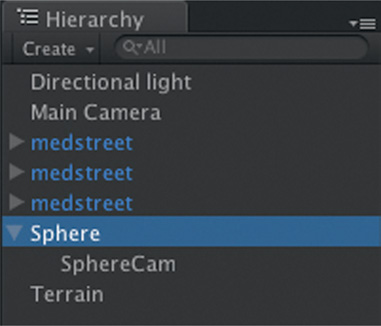
Step 14. Drag and drop the SphereCam onto Sphere in the Hierarchy as shown in Figure 2.9.
FIG 2.9 SphereCam attached to the Sphere.
Step 15. If you try to play the scene at this point there will be an error reported saying “There are 2 audio listeners in the scene. Please ensure there is always exactly one audio listener in the scene.” This is because there is an audio listener attached to all cameras by default. As with the Highlander, in the end there can be only one … in your game. The audio listener is the component that listens out for audio sources in the game environment and ensures that they play at the right volume and in the correct speakers. To resolve the error, remove the audio listener from the SphereCam.
Step 16. Create a new JavaScript file and call it orbit. Enter the code in
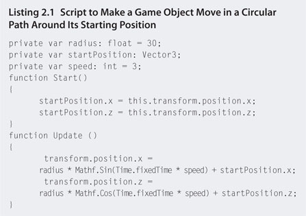
Step 17. Attach the JavaScript to the Sphere.
Step 18. Select SphereCam from Hierarchy such that the Camera Preview window opens in Scene.
Step 19. Ensure that you can see both Game and Scene views and press play.
Step 20. The camera preview for the SphereCam will display a moving scene as the Sphere moves about within the environment.
Step 21. Create a Plane and position and orientate it as shown in Figure 2.10.
Note: Steps 22–25 are only possible in the Pro version of Unity as the free version does not have the option Render Texture.
Step 22. In Project, select Create > Render Texture. Rename it to sphereCamView.
Step 23. Select SphereCam in the Hierarchy and in the Target Texture property of the Camera component select and set sphereCamView. If you select sphereCamView from the Project, you will see the view captured by SphereCam on this new texture's surface in the Inspector.
Step 24. Drag and drop the sphereCamView render texture onto the new plane in the Scene.
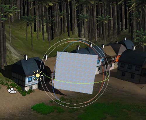
FIG 2.10 Adding a new plane to the scene.
Step 25. Play to see the view from SphereCam play out on the big screen in your scene. This technique can be used in your games for surveillance cameras, minimaps, or reflections in mirrors or water.
While cameras can be used to create a number of different visual effects, they are also important for optimizing a game's performance. For example, the camera's view volume should not be considered a trivial setting. As mentioned previously, all objects inside the view volume get drawn to the screen. The more objects to be drawn, the slower the frames per second. Even objects behind other objects and not noticeably visible will be considered by the game engine as something to be drawn. So even though an object doesn't appear on the screen, if it is inside the camera's view volume it will be processed. Therefore, if you have a narrow back street scene in a European city where the player will never see beyond the immediate buildings, the camera's far plane can come forward to exclude other buildings that cannot be seen anyway.
Whether the camera is looking at an orthographic or a perspective view, the coordinate system within the game environment remains the same.
2.3.2 Local and World Coordinate Systems
There are two coordinate systems at work in game environments: local and world. The local system is relative to a single game object, and the world system specifies the orientation and coordinates for the entire world. It's like having a map for the local layout of a city versus the longitude and latitude system used for the entire earth.
A game object can move and rotate relative to its local coordinate system or the world. How it moves locally depends on the position of the origin, the (0,0,0) point, within the model. Figure 2.11a shows a 3D model in Blender with the origin situated at the tip of the head, and Figure 2.11b shows it in
FIG 2.11 The effect of transformations based on local coordinates. (a) A model in Blender with the origin at the center top, (b) a model in Blender with the origin in the abdomen, (c) translation axes positioned in Unity for the model in a, (d) translation axes positioned in Unity for the model in b, (e) both models positioned at the world origin in a Unity Scene, and (f) both models rotated 90° about their local x axes.
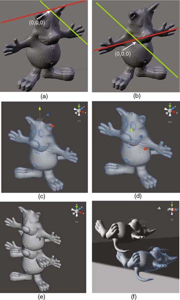
the center of the body. In Blender the default vertical axis is the z axis. The red and green lines in Figure 2.11a and 2.11b represent the x and y axes, respectively. When imported into Unity, the software automatically flips the z axis for you, making y the new vertical axis. As shown in Figure 2.11a and 2.11b, the origin of the model is carried across into Unity. When a model is selected, its origin is evident by the location of the translation handles used for moving the model around in the Scene. The location of the model's central point becomes an issue in Unity when positioning and rotating it. In Figure 2.11e, both models are placed in the world at (0,0,0) as set by the Inspector. As you can see, the models are placed in differing positions relative to their own central points. Figure 2.11f demonstrates how rotation is also affected by the model's origin. The model from Figure 2.11a rotates about the point in the center top of the head, whereas the model in Figure 2.11b rotates about its abdomen.
In Figure 2.12, the effect of rotations on local and world coordinate systems is illustrated. Any object at the world origin when rotated will orientate in the same way around local and world axes. However, when the model is not at the world origin, a rotation in world coordinates will move as well as reorient the model. Local rotations are not affected by the model's location in the world.
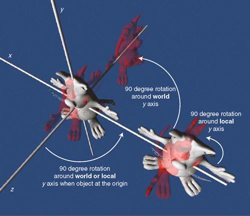
FIG 2.12 Local and world rotations affected by a model's position.
2.3.3 Translation, Rotation, and Scaling
Three transformations can be performed on an object whether it be in 2D or 3D: translation, rotation, and scaling.
Translation refers to moving an object and is specified by a vector in the same way the pirate in the previous section moved across the island. A translation occurs whenever the x, y, or z values of an object are modified. They can be modified all at once with a vector or one at a time. To move an object in the x direction by 5, the Unity JavaScript is:
this.transform.position.x += 5;
To move the object by 3 in the x, 5 in the y, and 8 in the z, in Unity JavaScript it could be written:
this.transform.position.x += 3;
this.transform.position.y += 5;
this.transform.position.z += 8;
or
this.transform.Translate(3,5,8);
Several examples of the Translate function are shown in Figure 2.13.
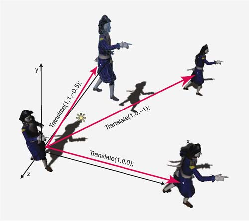
FIG 2.13 Using the Translate function to modify the position of a game object.
Rotation turns an object about a given axis by a specified number of degrees. An object can rotate about its x, y, or z axes or the world x, y, or z axes. Combined rotations are also possible. These cause an object to rotate around arbitrary axes defined by vector values. The Unity JavaScript to rotate an object about 90° about the y axis is
this.transform.Rotate(Vector3.up, 90);
To rotate 90° around the x axis, the script is
this.transform.Rotate(Vector3.right, 90);
and to rotate 90° around the z axis, the script is
this.transform.Rotate(Vector3.forward, 90);
Some of these rotations are illustrated in Figure 2.14.
Finally, scaling changes the size of an object as shown Figure 2.15. An object can be scaled along its x, y, or z axis. This can be achieved in Unity JavaScript by setting each scale value individually, thus:
this.transform.localScale.x = 3;
this.transform.localScale.y = 0.5;
this.transform.localScale.z = 10;
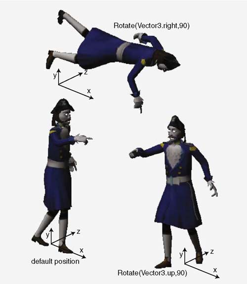
FIG 2.14 Rotating a game object with the Rotate function.
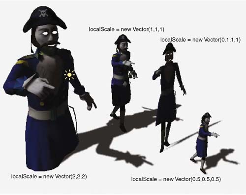
FIG 2.15 Scaling an object.
or all at the same time using a vector like this:
this.transform.localScale = new Vector3(3,0.5,10);
Values for the scale are always multiplied against the original size of the object. Therefore, a scale of zero is illegal. If a negative scaling value is used, the object is flipped. For example, setting the y axis scale to −1 will turn the object upside down.
Taking some time to orient yourself with both 2D and 3D space is necessary to understanding how objects will move around within your game. Fortunately, Unity takes the hard mathematics and hides it behind many easy-to-use functions. However, when something goes wrong in your game, it's nice to have some idea where to start looking.
2.3.4 Polygons and Normals
Chapter One introduced polygons as the small shapes, usually triangles and sometimes squares, that make up 2D and 3D meshes (or models). A polygon in a mesh also represents a plane. A plane is a 3D object that has a width and height but no depth. It is completely flat and can be orientated in any direction, but not twisted.
FIG 2.16 A plane and its normal.
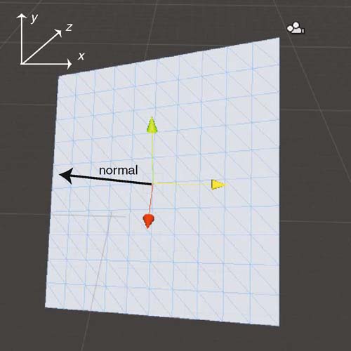
The sides of planes are defined by straight edges between vertices. Each vertex has an associated point in space. In addition, planes only have one side. This means that they can only be seen when viewed from above. To see this, open Unity and create a plane game object. Rotate the plane around to the other side. It will become invisible, but it will still be there.
In order to define the visible side of a plane, it has an associated vector called a normal. This is not to be confused with normalization of a vector into a unit vector. A normal is a vector that is orthogonal (90°) to the plane as shown in Figure 2.16.
Knowing the normal to a plane is critical in determining how textures and lighting affect a model. It is the side the normal comes out of that is visible and therefore textured and lit. When a model is created in a 3D modeling package such as Blender the normals are usually facing outward from the object. Figure 2.17 shows a model in Blender with the normals for each plane shown in blue.
The angle that a normal makes with any rays from light sources is used to calculate the lighting effect on the plane. Figure 2.18 illustrates the vectors and normal used in calculating the effect of light on a plane. The closer the normal becomes to being parallel with the vector to the light source, the brighter the plane will be drawn. This lighting model is called Lambert shading and is used in computer graphics for diffuse lighting. Further elucidation of shading is presented in later chapters.
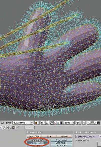
FIG 2.17 A 3D model in Blender showing normals for each plane in blue. To turn this on, select the object and, in Edit Mode, click on Draw Normals in the Mesh Tools 1 panel.
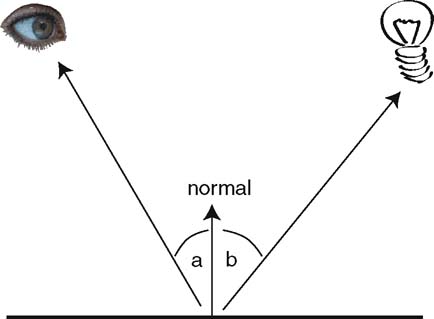
FIG 2.18 Vectors used in calculating the strength of lighting on a plane; a vector to the viewer, the normal and a vector to the light source.
Meshes and Normals
Step 1. Download Chapter Two/PolyNormals.zip from the Web site, unzip, and open.
Step 2. In the Scene, create two plane objects and place them side by side.
Step 3. Add a directional light and rotate it so the light is hitting the planes at about 30°.
Step 4. Take the CrumbleMesh.js script and attach it to both planes.
Step 5. Select one of the planes in the Hierarchy, and tick the box next to Recalculate Normals of the Crumble Mesh Script component in the Inspector.
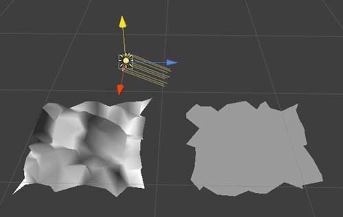
Step 6. Play. You will be able to see the planes deforming as shown in Figure 2.19.
FIG 2.19 Two planes, a directional light, and a script to deform the surfaces. The plane on the left has its normal recalculated.
Step 7. Examine the CrumpleMesh script in the editor. Although the code itself is complex for a beginner programmer, there are a few lines of significance to point out. First, the script uses a class called Perlin(). The complete code for this can be found in the Plugin folder in the Project. The specifics of this at this time are not important but it is the cause of the smooth deformation movement of the planes. It is essentially a fractal algorithm for a random yet smooth movement. Each vertex of the plane's mesh is captured and translated using a value from the Perlin function. The line
var mesh : Mesh = GetComponent(MeshFilter).mesh;
is the Unity method for getting the mesh of any object to which the script is attached. At the very bottom of the script is the option to recalculate the normal. The script will do this when the tick box you selected before is ticked. This is the reason why one plane has updated shading and the other does not. The plane without the recalculated normal keeps the shading it started with on each polygon because as far as the rendering system is concerned, the angle between the light source and the normal has remained unchanged. It is possible to move vertices around and leave the normals where they were. In this case, the original normals are no longer orthogonal with their polygons. The line
mesh.RecalculateNormals();
ensures that all normals are recalculated and made orthogonal to their polygons after the polygons' vertices are moved. In this case, recalculating the normal is essential to getting the correct lighting effect on the surface.
2.4 Two-Dimensional Games in a 3D Game Engine
Although 3D game engines aren't often written to support 2D game creation, many developers use them for this purpose because (a) they are familiar with them, (b) they don't have to purchase software licenses for other development platforms, and (c) the engines provide support for multiple platforms and game types. As is the case with Unity, although it is not strictly a 2D game development environment, it can port to Android and iOS, making it attractive to developers. In addition, mechanics that are relevant in 3D games are equally so in 2D games.
To create a 2D game in a 3D environment, the one degree of freedom is removed. In the case of the following hands-on section, the y axis is all but ignored and the camera is placed into orthographic mode looking down on the scene as though it were playing out on the top of a table.
![]() Unity Hands On
Unity Hands On
A 2D Vector-Based Space Shoot ‘em Up
Step 1. Download Chapter Two/Basic2DGameStarter.zip from the Web site, unzip, and open in Unity. In the Project, double-click on basicgame of the Scenes folder to open the scene. The Scene will appear with a planet and gun turret in the middle and a rocket ship to the lower left. The artwork used here is freely available from http://www.openclipart.org/.
Step 2. Press play. Nothing will happen, but you will notice that you can click on the Quit button and go back and forward between the game screen and the main menu. A fuller version of the game will be created as you proceed through this book.
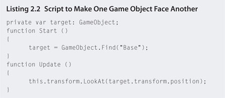
Step 3. The objective in this hands-on session will be to get the rocket ship to attack the planet. To begin, create a new JavaScript file and call it attack. Attach the file to the Enemy game object in the Hierarchy. Open attack.js with the script editor. Add the script from Listing 2.14
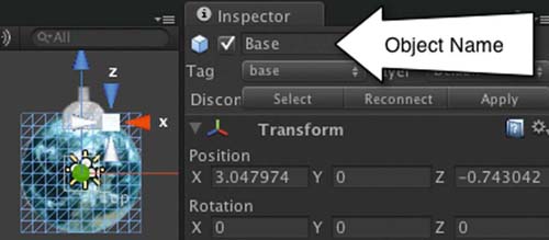
Step 4. Save and play. The rocket ship will turn to face the planet. In Update(), the function LookAt() is used. It takes a target position and turns the game object to face it. In Start(), the target is set to the object called base, which is also the name given to the object. This object is called “Base.” To see this in the Inspector, select the base in the hierarchy. The name of the planet object is shown in Figure 2.20.
FIG 2.20 The Inspector view of a game object's name.
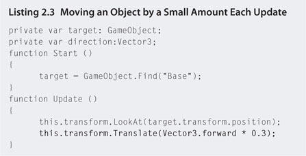
Step 5. To make the rocket ship move toward the planet, modify the code to that listed in Listing 2.3
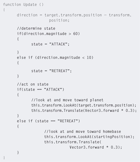
Step 6. Save and play. The rocket ship will move toward the planet. However, when it gets to the planet it will stop moving and start flipping back and forth. Why? Each update, the rocket looks at the base and moves toward it. When it is on top of the base it looks at it and then moves forward. This moves it slightly away. The next update it flips around to look at the base again and moves a little toward it. infinitum.
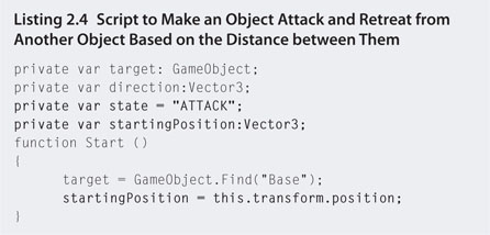
Step 7. To make the rocket move away from the planet when it gets too close, we can test for the distance the rocket is from the planet and turn it back toward its starting position when it comes within a specific distance. To do this, modify your script to that in Listing 2.4.
Step 8. Save and play. The rocket will move back and forth between the planet and its starting location. This is achieved by creating a new variable called state that stores the rocket's current objective or goal. This is a very simple version of a finite state machine used commonly in games for controlling AI. If the rocket is further than 60 away from the planet it will go into attack mode. If it gets closer than 10 it will retreat.
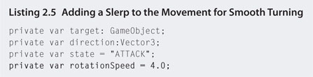
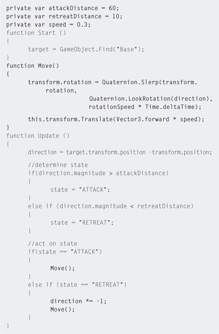
Step 9. So far we've created a rather unnaturally moving rocket ship. It will look better if it curves to turn rather than simply flipping on the spot. To achieve this, modify your code to that in Listing 2.5.
Step 10. Save and play. The rocket will go toward the planet and when it gets too close will turn away. Once it reaches the bounds of the attack distance it will turn around and approach the planet again. Major changes to this code are the variables added to the top and the Move() function. The reason for creating variables for all the static values in the code is to make them easy for editing. If you want to play around with the values to see how it changes the behavior of the rocket, it can be done easily without trawling through the rest of the code. In addition, you can expose them by removing the private keyword and they will become editable in the Unity Editor's Inspector. The Move() function is more complex and needs further explanation before proceeding.
2.4.1 Quaternions
In 3D space there are three axes around which an object can rotate. These rotations are analogous with the rotational movements of an aircraft. As shown in Figure 2.21, a rotation about the x axis (b) creates pitch, a rotation about the z axis (c) creates roll, and a rotation about the y axis (d) develops yaw.
The angles used to specify how far to rotate objects around these axes are called Euler angles. Euler angles are often used in 3D software and game engines because they are intuitive to use. For example, if someone asked you to rotate around your vertical axis by 180° you would know this meant to turn around and look in the opposite direction.
However, there is a fundamental flaw in using Euler angles for rotations in software that can cause unexpected rotational effects. These angles are applied one after the other and therefore have a mathematical compounding effect. This consequence is seen in the mechanical devices used to stabilize aircraft, ships, and spacecraft—the gyroscope.
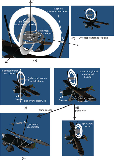
A simple gyroscope is illustrated in Figure 2.22. It consists of three discs attached to the outer structure of a vehicle (in this example a plane) and attached to each other at pivot points each representing rotations around the x, y, and z axes. These rotating discs are called gimbals. As the plane yaws, pitches, and rolls, the gyroscope responds to the forces with the rotating of the discs at their pivot points. The idea is that a plate attached to the central, third gimbal remains upright at all times. Navigational systems attached to the gyroscope monitor this plate to determine the orientation of the vehicle. For example, if the vehicle were on autopilot, the objective would be to keep it upright and level to the ground, and any change in the gyroscope's orientation assists with pitch, yaw, or roll corrections.
A situation can occur in which two of the gimbals become aligned, as shown in Figure 2.22d. This is called a gimbal lock. At this point, it can either be corrected with the right maneuver (e) or cause erratic behaviors. In Figure 2.22f, the third gimbal cannot rotate back such that the central plate is facing upward, as its pivot points won't allow it. In some circumstances, alignment of the first and second gimbals can also cause the third gimbal to flip upside down, even if the vehicle itself is not upside down. When this occurs, the navigational system becomes very confused as it attempts to realign the vehicle.
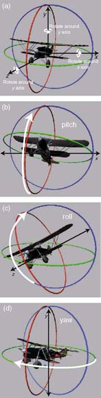
FIG 2.21 Individual rotations about the x, y, and z axes in 3D space.
While this is a simplistic examination of gimbals, the issue of gimbal lock is a reality. It is a mechanical reality that was experienced by the astronauts of the Apollo missions and it is a virtual reality when using Euler angles to rotate 3D objects. Just as the gyroscope compounds the rotations of the outer gimbal inward, multiplying x, y, and z angle rotations one after the other in software systems produces the same errors.
FIG 2.22 A simple gyroscope. (a) Gimbals and rotation points; (b) attaching the gyroscope to a plane; (c) a clockwise yaw of the plane forces the first gimbal to move with it, as it is attached and has no freedom of movement in that direction, while the second gimbal is free to move in response in the opposite direction; (d) a 90° yaw will cause the first and second gimbals to align, thereby entering a state of locked; and (e) after the first and second gimbals become locked, a pitch will retain the integrity of the third gimbal. (f) However, a roll can cause erratic behavior from gimbal 3.
Quaternions to the Rescue
Quaternions are mathematical constructs that allow for rotations around the three axes to be calculated all at once in contrast to Euler angles, which are calculated one after the other. A quaternion has x, y, and z components, as well as a rotation value.
In games using Euler angles, rotations can cause erratic orientations of objects. This is illustrated in Figure 2.23 where the rotations of two planes are compared. Each plane is rotated continually around the x, y, and z axes by
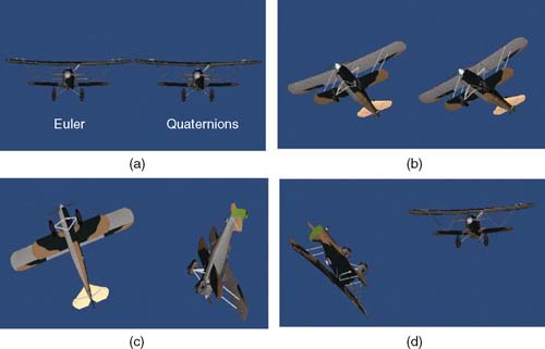
FIG 2.23 Two planes rotated 1° around each axis every frame. One uses the Euler angle to calculate the other quaternions. (a) Planes begin aligned, (b) planes remain aligned at first, (c) once the x angle becomes 90 for the Euler plane its rotations go off course with respect to the quaternion plane, and (d) even further in the simulation.
1°. The plane on the left in Figure 2.23 is rotated using Euler angles and the other uses quaternions. The movement of the quaternion plane is smoother.
Quaternions are used throughout modern game engines, including Unity, as they do not suffer from gimbal lock.
![]() For Research
For Research
Quaternions
If you are interested in the complex inner workings of quaternions, check out Visualizing Quaternions by Andrew J. Hanson (2006 ISBN: 978-0120884001).
Although the rotation value for the transform component of GameObjects appears as Euler x, y, and z values in the inspector, Unity uses quaternions for storing orientations. The most used quaternion functions are LookRotation(), Angle(), and Slerp().
LookRotation() given a vector will calculate the equivalent quaternion to turn an object to look alone the original vector. This means this.transform .rotation = Quaternion.LookRotation(target.position – this .transform.position) achieves the same result as this.transform .LookAt(target.transform.position).
The Angle() function calculates the angle between two rotations. It might be used to determine if an enemy is facing directly toward or away from the player.
Slerp() takes a starting rotation and an ending rotation and cuts it up into small arcs. It is extremely effective in making rotating objects change from one direction to another in a smooth motion. Originally the previously created rocket ship was flipping back and forth as it changed direction. This occurs when the objects goes from the original-facing direction to the goal-facing direction in one frame. Slerp() breaks this rotation up so that small parts of it occur with each frame instead of all in one go.
Now that you have a little understanding of quaternions, we can continue examining the Move() function from Listing 2.5. It contains two quaternion functions: LookRotation() and Slerp(). LookRotation() takes a vector and turns it into a quaternion. It is being used here to convert the direction vector into a quaternion. This is required by the Slerp() function, which uses the rotation speed and the time between the drawing of frames (Time.deltaTime) to carve up the complete turn angle into smaller pieces, making the rocket ship turn around in a smooth motion.
![]() Unity Hands On
Unity Hands On
Quaternions
Step 1. To create bullets that come from the rocket, create a plane by selecting GameObject > Create Other > Plane from the main menu. If a small white plane does not appear in the Game or Scene, select the new Plane from the Hierarchy and set its position values to (0,0,0). It should appear somewhere near the planet.
Step 2. Create a red-colored material and add it to the plane.
Step 3. Set the scale x, y, and z values for the plane to (0.05,0.05, 0.05). It will now appear as a small red dot on the screen.
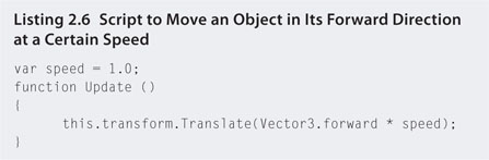
Step 4. Create a new JavaScript file and call it moveBullet. Enter the code shown in Listing 2.6 and attach it to the plane.
Step 5. Save and play. The plane will move upward and off the screen.
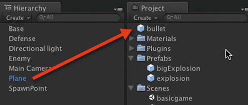
Step 6. From the Create menu in the Project, select Prefab. Change the name of the newly created prefab to bullet. A prefab is a game object in waiting. It's not in the game environment, but is ready to be called up at any time. The prefab is a template that can be used over and over again.
Step 7. Drag and drop the plane from the Hierarchy onto the bullet in the Project as shown in Figure 2.24. When you click on the bullet it will now have all the same properties as the plane. Ensure that the bullet has its transform position set to (0,0,0), its rotation to (0,0,0), and its scale to (0.05,0.05,0.05) in the Inspector. The bullet is going to be attached to the rocket. To ensure its relative position to the rocket, the bullet must be at the origin. Then when attached to the rocket it will be located at the rocket's position coordinates.
FIG 2.24 Creating a prefab.
Step 8. Delete the original plane from the Hierarchy. It will disappear from the Scene and Game but a template of it is now stored in the Project.
Step 9. Open attack.js in the script editor and modify the code as shown in Listing 2.7. Note that as the code is getting longer only snippets of the areas around the new code are shown. Anywhere “…” appears assume the code in this part remains unchanged.
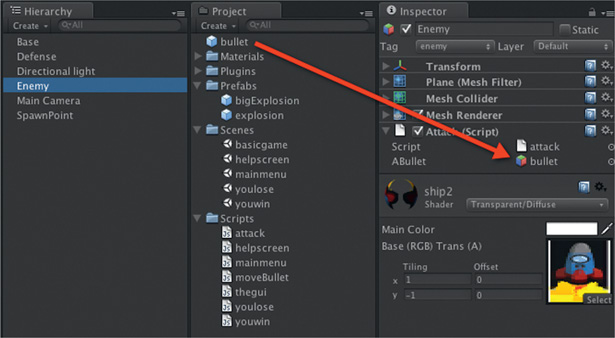
The variable aBullet is exposed. Select Enemy and drop the bullet prefab from the Project onto the aBullet location in the attack script shown in the Inspector. This is illustrated in Figure 2.25. Because it is possible to drag the bullet prefab onto the script to set the variable, you can drag and drop any game object onto it, meaning that the rocket's bullets could be any game object.
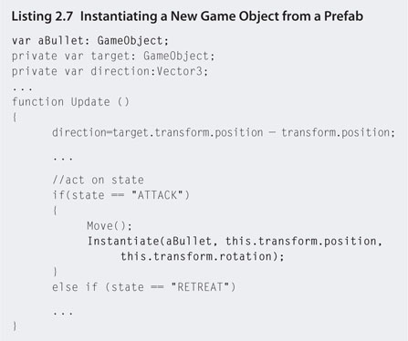
FIG 2.25 Dogs in the yard of a castle by Tabytha de Byl aged 4.
Step 10. Save and play. As the rocket moves in for the attack it starts creating bullets from the prefab. The bullet prefab has the moveBullet script attached to it that moves the bullet in a forward motion. However, because the bullet is created at the rocket's location and orientation, it travels forward relative to the rocket and therefore in the direction the rocket is facing.
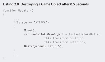
Step 11. The current attack script will continue creating bullets as long as the program runs. Each bullet is a new game object. As the game runs you will see the Hierarchy fill up with bullet clones. This can become problematic as the game gets clogged up with game objects, many of which are off the screen and traveling toward infinity. They need to be destroyed. To do this, add the code shown in Listing 2.8 to the attack script.
Step 12. Save and play. The Destroy() function will delete the specified game object after the given amount of seconds (in this case 0.5 seconds). As the Destroy() function needs to know which object to destroy, a local variable is created to hold the instantiated game object. This is then passed to Destroy().
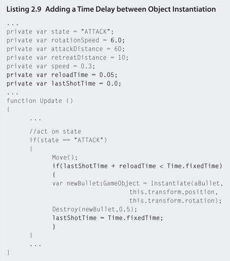
Step 13. Instead of a continued stream of bullets it will look better if there is a delay between them. You can adjust the delay to whatever reloading speed you want. To add this functionality, modify the attack script to that in Listing 2.9.
Step 14. Save and play. The Time.fixedTime value, stores the time since the game started playing. The variable lastShotTime records when the last bullet was shot, and reloadTime is the time allowed between shots. If a time interval of reloadTime has passed since the last shot, another bullet can be instantiated. Also, note that the rotationSpeed for the rocket has increased to give it more attack time.
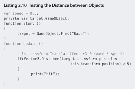
Step 15. To test if the bullets are hitting the target, open and modify the code for the moveBullet script to that in Listing 2.10. The code tests the distance between a bullet and the base. If that distance is less than 5, a hit is registered. For now, the hit is only displayed in a print statement that shows up in the console.
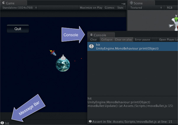
Step 16. Save and play. When a bullet hits the base, the game will print out hit in the message bar and console (Figure 2.26). Doubleclicking on the message bar text will open the console.
FIG 2.26 Print messages showing up in the message bar and console.
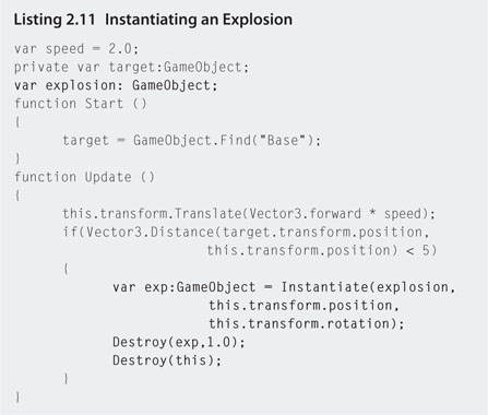
Step 17. To cause a small explosion when a bullet hits the base, modify moveBullet to instantiate an explosion game object when it hits, as shown in Listing 2.11.
Step 18. Save. Before playing, select the moveBullet script from the Project and then locate the explosion Prefab and drag it onto the exposed variable Explosion in the Inspector window.
Step 19. Play. When a bullet hits the base, an explosion will occur instead of print. The explosion prefab is a particle system. You will learn more about these in later chapters. Just after the explosion is instantiated and set to be destroyed, the script also destroys the bullet game object. This will ensure that the bullet doesn't stay alive in the game environment after it has hit the base.
In this hands-on session you've learned some basic uses of vectors in a simple 2D game environment.
2.5 The Laws of Physics
Game players bring their own experience of the real world to a game environment. They understand that gravity makes things drop, acceleration changes the speed of an object, and when an object hits another object a reaction, such as bouncing or exploding, will occur based on the object's composition.
These expectations within game environments are essential to establishing the player's suspension of disbelief—a psychological state in which a player accepts the limitations of a medium in order to engage with the content. This can include anything from low-quality graphics to flying aliens. Anything that messes with the player's suspension of disbelief causes them to disengage and lose interest, such as being woken from a dream. A big part of ensuring a game environment is making the virtual world act and react like the real one.
The laws of physics are a set of complex rules that describe the physical nature of the universe. Adhering to these rules when creating a game is key to creating a believable environment in which the player interacts. Sometimes the laws are bent to suit narrative; however, they essentially remain static throughout. For example, players in a modern warfare game, taking place on earth, would expect gravity to react for their character as it does for them in the real world. In the case of science fiction, the effects of gravity may be altered to fit the story.
Physics is a fundamental element in games as it controls the way in which objects interact with the environment and how they move.
Although physics covers topics such as Einstein's theory of relativity and thermodynamics, the key ones used in game environments are Newton's three laws of motion and the law of gravity.
2.5.1 The Law of Gravity
Although it is a myth that an apple fell on Newton's head, he did devise his theory of gravity while watching an apple fall from a tree. In Newton's publication the Principia, the force of gravity is defined thus:
Every particle of matter in the universe attracts every other particle with a force that is directly proportional to the product of the masses of the particles and inversely proportional to the square of the distance between them.
In short, this means the bigger an object, the more it attracts other objects and that this attraction gets stronger the closer it is. Kepler also used this law, a century later, to develop his laws of planetary motion.
In game environments, applying a downward velocity to an object simulates gravity. The y coordinate of the object's position is updated with each game loop to make it move in a downward direction. If you were to code this in Unity, the JavaScript would look something like this:
(2.4)
Unfortunately, the actual calculation for real gravity would be a little more complex than taking away one as the effect of earth's gravity is a downward acceleration of 9.8 meters per second.2 This means the downward speed of an object gets faster by 9.8 meters per second with each second. An object starting with a speed of 0 after 1 second will be moving at 9.8 meters per second, after 2 seconds it will be moving at 19.6 meters per second, and after 3 seconds it will be moving at 29.4 meters per second.
In addition, a game loop may not take exactly 1 second to execute. This will throw out any calculations you attempt with each loop update on a second by second basis.
Fortunately, game engines take care of all the mathematics and allow you to set just one gravity value for your environment. Let's take a look at how Unity does it.
![]() Unity Specifics
Unity Specifics
Gravity
From the main menu, select Edit > Project Settings > Physics. The Physics properties will open in the Inspector as shown in Figure 2.27. The default setting is for a downward acceleration of 9.81 meters per second.3
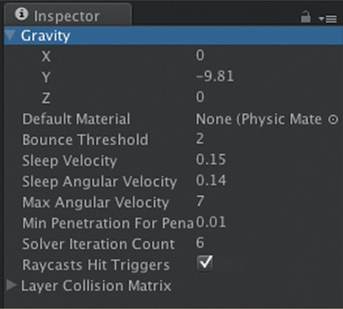
FIG 2.27 Unity's Physics properties.
As you can see, depending on your own game environment, gravity can be set in any direction, including upward and sideways.
![]() Unity Hands On
Unity Hands On
Applying Gravity
Step 1. Start Unity and create a new project. Orient the Scene such that the y axis is pointing upward. Position the camera so that it has the same view as shown in the Scene. To do this, select the camera from the Hierarchy and then from the main menu GameObject > Align with View.
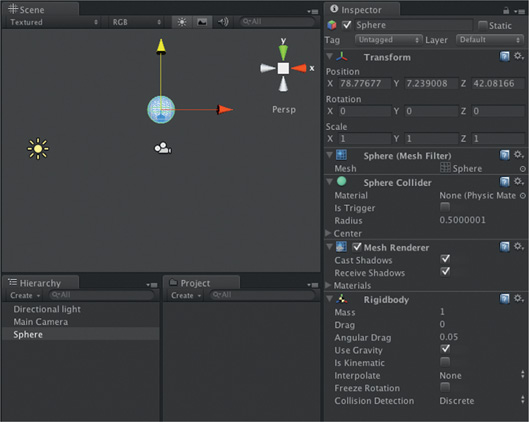
Step 2. Add a sphere to the Scene and position it at the top of the camera view. With the sphere selected in the Hierarchy, select from the main menu Component > Physics> Rigidbody. The result of this will be a new component added to the sphere in the Inspector, as shown in Figure 2.28. The Rigidbody component makes the sphere part of Unity's physics processing and as such gravity will be applied to it.
FIG 2.28 A Scene with a Sphere that has a Rigidbody attached.
Step 3. Press play. The sphere will fall downward.
Step 4. Press stop and change the gravity via the main menu's Edit> Project Settings > Physics; in the Inspector click on Gravity to expand. You may want to set it to a positive y value or even have it go to the side with a change to the x. You choose.
Step 5. Press play to see the effect of the new gravity settings.
2.5.2 The First Law of Motion
Every body continues in its state of rest, or of uniform motion in a straight line, unless it is compelled to change that state by forces impressed upon it.
This means that an object will remain stationary and a moving object will keep moving in the same direction unless push or pulled. In the real world, a number of different forces act to move or slow objects. These include gravity and friction. In addition, objects colliding with each other will also act to change their movement.
![]() Unity Hands On
Unity Hands On
Newton's First
Step 1. Create a new Unity Project. Ensure that the y axis is pointing up and position the Main Camera to the same view.
Step 2. Select GameObject > Create Other > Plane from the main menu. Resize the plane to twice its original size to create a large ground area. You can do this by pressing “R” while the plane is selected or changing the scale x, y, and z values in the Inspector to 2. Add a directional light. Add a grass or dirt seamless texture to the plane.
Step 3. Select GameObject > Create Other > Cube from the main menu. Zoom in to center the cube in the Scene. Lift the cube so that it is slightly above the ground.
Step 4. With the cube selected in the Hierarchy, select Component> Physics > Rigidbody from the main menu to add physics processing to the cube.
Step 5. Press play. The cube will fall until it hits the ground and stops. Although the plane doesn't have a Rigidbody attached, it does have a Collider. Select plane in the Hierarchy and look for the Box Collider in the Inspector. This collider is used by the physics system. Although the ground plane is not affected by the cube hitting it, the cube, because it has a Rigidbody, is stopped by the collider of the plane.
Step 6. Lift the cube higher above the plane. Add a Rigidbody to the plane.
Step 7. Press play. Note that the plane and the cube both fall at the same rate.
Step 8. Select the plane from the Hierarchy and find its Rigidbody component in the Inspector. To add air friction, set the value of Drag to 10.
Step 9. Press play. The plane will fall away more slowly than the cube. When the cube hits the plane, the plane will speed up and possibly flip, depending on where you've placed the cube with respect to the plane.
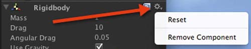
Step 10. Remove the Rigidbody from the plane by selecting the small drop-down menu as shown in Figure 2.29.
FIG 2.29 Removing a component from a GameObject.
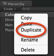
Step 11. Select the cube in the Hierarchy, right-click on it, and select Duplicate as shown in Figure 2.30. Duplicating a GameObject after it has had components, such as a Rigidbody, attached to it will ensure that the duplicate has all the same attachments. Move the duplicate cube, which will be in the exact same location as the original.
FIG 2.30 Dogs in the yard of a castle by Tabytha de Byl aged 4.
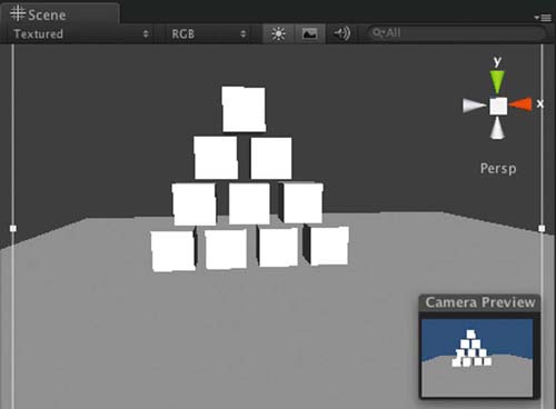
Step 12. Continue duplicating and moving to build a stack of cubes as shown in Figure 2.31.
FIG 2.31 A stack of duplicated cubes, all with Rigidbodies.
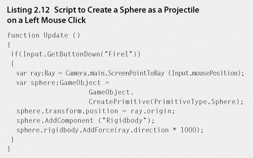
Step 13. In the Project, create a new JavaScript file and call it fire. Open it in the script editor and enter the code in Listing 2.12. Save the script and attach it to the Main Camera.
Step 14. Save and play. A click in the Game will create a sphere at the click location and project it in the direction the camera is facing. Before a force is added to push the sphere, the AddComponent() function is used to add a Rigidbody component to the sphere as it is not attached by default. The ScreenPointToRay() takes the mouse click location and turns it into a vector (called a ray) that starts at the click location and continues in the direction the camera is facing. This direction is used as the push force on the sphere, propelling it forward.
Step 15. Gravity still affects the sphere. To see it in action, change the multiplier for the AddForce() function from 1000 to 100.
2.5.3 The Second Law of Motion
The acceleration produced by a particular force acting on a body is directly proportional to the magnitude of the force and inversely proportional to the mass of the body.
This means that a larger force is required to move a heavier object. In addition, a heavier object with the same acceleration as a lighter object will cause more destruction when it hits something as the force will be greater. Imagine throwing a bowling ball and a tennis ball at a wall with the same acceleration. Which one is going to leave a bigger hole?
![]() Unity Hands On
Unity Hands On
Newton's Second
Step 1. Begin by opening the Unity project from Section 2.5.2. Open the fire script and ensure that the AddForce() multiplier is set to 1000, for example, AddForce(ray.direction * 1000).
Step 2. In the Hierarchy, select each cube in turn, locate the Rigidbody component in the Inspector, and set the Mass to 10.
Step 3. Press play. Note that the heavier cubes are now more difficult to knock over with the sphere.
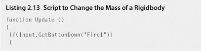
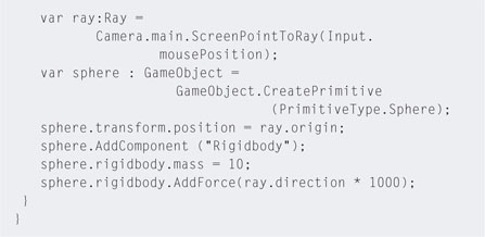
Step 4. Edit fire.js to increase the mass of the sphere as shown in Listing 2.13. Save and play.
Step 5. Because the sphere has more mass, the added force has less effect. However, you may be able to get it to roll along the ground. The extra mass will be enough to knock over the cubes.
Step 6. Try setting the AddForce() multiplier to 10,000. Note that because the mass has increased 10-fold, the force required to move the sphere in the same way must also increase 10-fold.
2.5.4 The Third Law of Motion
To every action there is always opposed an equal reaction; or, the mutual actions of two bodies upon each other are always equal, and directed to contrary parts.
This can be rephrased to the well-known adage for every action there is an equal and opposite reaction. When a truck hits a car, energy from the movement of the truck is transferred to the car and it is propelled away from the truck. If a car hits another car of a similar size, some of the energy is transferred to the second car, while some goes back into the first car. If a car hits a brick wall, chances are most of the energy will go back into the car. This energy needs to go somewhere. In the case of cars, specially designed crumple zones absorb the energy. For a tennis ball, some of the energy is absorbed by the rubbery nature of the ball and the rest is used to propel the ball away. In other words, collisions occurring in the real world have an effect on the environment as well as the object.
The examples thus far examined in Unity see energy from an initial force transferred or totally absorbed by the objects. For a heavy sphere, cubes are knocked over easily, whereas a light sphere hits the cubes and drops straight to the ground. This rarely happens in the real world where things tend to bounce, to some degree. In Unity, adding a physics material to an object can simulate these extra effects.
Physics Materials
In Unity, a physics material is created in the Project and then added to the object's Collider component. A physics material sets values for bounce and friction. The bounciness of an object can be set between 0 (no bounce) and 1 (full bounce) to simulate how much of a collision's force comes back to the object. For example, for a tennis ball, set bounce to 1. The friction value determines how well an object holds onto another surface when rubbed together. For example, rubber on concrete has a high friction value, whereas stone on ice has a low friction value. Friction is a force that slows down movement. Friction can be set to 0 (no friction) to an infinite number (total friction).
![]() Unity Hands On
Unity Hands On
Newton's Third
Step 1. Create a new Unity project with a sloping plane and cube as shown in Figure 2.32. Attach a Rigidbody to the cube. Press play and watch the cube drop down until it hits the plane and then rolls the rest of the way. Try to rotate the cube such that one side is parallel to the plane as shown.
Step 2. To create physics material, in Project select the Create menu and choose Physics Material, as shown in Figure 2.33. Rename the material box.
Step 3. Select the cube in the Hierarchy and locate its Box Collider in the Inspector. The first property will be Material. Click on the small circle to the very right of it and select the box physics material from the pop-up window. If you play the application at this point, there will be very little effect. Select box from the Project. The view of this physics material will appear in the Inspector as shown in Figure 2.34. Set the Bounciness value to 1. Press play to see the effect.
Step 4. To get a higher bounce, set the Bounce Combine value to Maximum. These combine values tell the physics engine how to work out the effect when two objects collide. When set to maximum it will apply the maximum bounce factor out of the two objects. If you set it to minimum the cube will not bounce, as the plane has no bounciness value.
Step 5. Now try setting all the box physics material values to 0 and the Friction Combine to minimum. Press play. With no bounce or friction, the box will fall to the plane and then slide down as if the surface was made of ice.
FIG 2.32 The initial scene required to demonstrate physics materials.
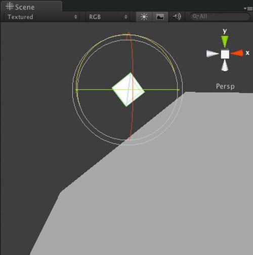
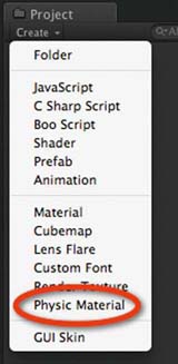
FIG 2.33 Creating physics material.
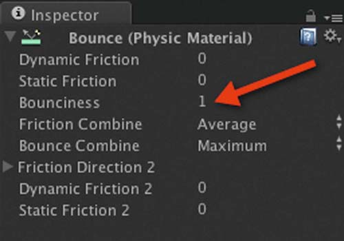
FIG 2.34 The Inspector view of physics material.
2.6 Physics and the Principles of Animation
In their book The Illusion of Life, Disney animators Ollie Johnston and Frank Thomas introduce 12 rules to be applied when creating animated films.
These are
Squash and stretch:
The deformation of objects in reaction to the laws of physics; for example, a tennis ball hitting a wall squashes on collision.
Anticipation:
Presenting short actions or hints to a viewer of what is about to happen; for example, a person about to jump in the air will bend their knees first.
Staging:
Presenting an idea such that no mistake can be made as to what is happening; for example, viewing an angry person's face gives a better impression of their mood than the back of their head.
Straight-ahead action and pose to pose:
These are animation drawing methods. Straight-ahead action refers to drawing out a scene frame by frame. Pose to pose refers to drawing key frames or key moments in a scene and filling in the gaps later.
Follow-through and overlapping action:
This is the way in which momentum acts on a moving object to cause extra motion even after the initial force has stopped; for example, a baseball pitcher's arm does not stop moving the moment the ball leaves his hand. In addition, his legs and body also move in response to the action. Overlapping action occurs when secondary objects move with the main object.
Slow in and out:
Natural movement in which there is a change in direction decelerates into the change and accelerates out; for example, a car turning a corner slows into the corner and accelerates out. A person jumping will slow into the impact with the ground and speed up as he pushes off the ground with his legs.
Arcs:
Motion in animals and humans occurs along curved paths. This includes the rotation of limbs and the rise and fall of a body when walking. The same curved movement is also found in the trajectory of thrown objects.
Secondary actions:
These animations support the principal animation. They give a scene more realism; for example, a person walking along the street won't just be moving his legs. His arms might swing, he may be talking, and his hair could be flowing with the breeze.
Timing:
This refers to the speed of actions. It is essential for establishing mood and realism; for example, a fast-moving character will appear to be in a hurry, whereas a slow-moving character portrays lethargy or disinterest. For realism, the correct timing of actions with motion and sound is critical. Slow animated walking characters can look like they are slipping across the ground if their forward movement and leg cycles are not matched. A delay between an action and a sound, such as a bomb exploding and the associated sound effect, adds to suspension of disbelief.
Exaggeration:
Perfect imitations of the real world in animation can appear dull and static. Often it is necessary to make things bigger, faster, and brighter to present them in an acceptable manner to a viewer. Overexaggeration is also used in physical features of characters for the effects of physics; for example, in Warner Bros.' coyote and roadrunner films, when the coyote is about to fall from a great height, the time he spends in the air realizing his predicament is exaggerated far beyond what normal gravity would allow.
Solid drawing:
This is the term given to an animator's ability to consider and draw a character with respect to anatomy, weight, balance, and shading in a 3D context. A character must have a presence in the environment, and being able to establish volume and weight in an animation is crucial to believing the character is actually in and part of the environment.
Appeal:
This relates to an animator's ability to bring a character to life. It must be able to appeal to an audience through physical form, personality, and actions.
All but a couple of the preceding principles of animation can be conveyed in a game environment through the physics system. They are consequences of physics acting in the real world. We subconsciously see and experience them every day, albeit not with as much exaggeration as a game, and come to expect it in the virtual environment.
In the following hands-on sections you will get a chance to see how these principles can be applied in your own games.
2.6.1 Squash and Stretch
2D Boy's two-dimensional adventure World of Goo features many moving balls of Goo. Each time Goo accelerates it becomes elongated along the direction of movement, and it decelerates and squashes when it collides with another object. Such movement occurs in the real world and is explained by Newton's laws.
While game-based physics engines do allow for the creation of bouncy objects, typically they do not provide real-time squashing and stretching algorithms for the actual game object. The rigid body attached to a game object to simulate physics by very definition remains rigid even though its movement suggests otherwise. In most cases, it is too processor intensive in 3D environments to squash and stretch all objects, but just for fun this hands-on session will show you how to do it in Unity.
![]() Unity Hands On
Unity Hands On
Squash and Stretch
Step 1. Download Chapter Two/AnimPrinciples.zip from the Web site, unzip, and open in Unity. In the Project, double-click on squash in the Scenes folder to open the scene. The warehouse scene from one of the Unity online resources will be visible.
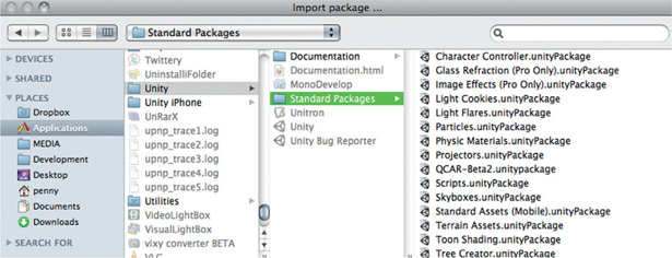
Step 2. We want to be able to move around inside the warehouse and need to add a first person controller (FPC). Select Assets > Import Package from the main menu, and select the Character Controller package (Figure 2.35).
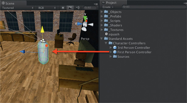
Step 3. Unity will decompress the package and then show you the files it is about to add to your project. Select all and click on Import. A folder called Standard Assets will appear in the Project. Inside this folder locate the FPC and drag it into the Scene. A capsule-shaped object with a camera attached will show in the Scene, as illustrated in Figure 2.36.
FIG 2.36 Adding a First Person Controller to a scene.
Step 4. Delete Main Camera from the Hierarchy. There is already a camera attached to the FPC and the Main Camera is no longer needed.
Step 5. Play. The FPC will fall straight through the floor. Why? The warehouse mesh does not have any colliders and therefore there is nothing to stop the FPC falling. Each surface of the mesh requires a mesh collider to be added.
Step 6. In the Hierarchy, select wareHouseFBX and expand it by clicking on the small triangle to the left of its name. This model is made up of a number of meshes. They are called polySurface88, polySurface89, and so on. Select polySurface88, scroll to the bottom of the list, and SHIFT select polySurface 1518. With all the surfaces selected, go to the main menu and select Component > Physics> Mesh Collider. Each surface will have a mesh collider added to it using its own mesh shape. Quickly scan through the polySurface meshes individually and note the new Mesh Collider component added and that the Mesh property of this is set to its own mesh.
Step 7. Play. The FPC will fall and hit the floor. You will be able to move around with the arrow or WASD keys and jump with the spacebar. If the FPC falls through the floor it will be because it either starts slightly merged with the floor or the floor does not have a mesh collider. Move the FPC up a little and check the floor mesh for a collider and try again.
Step 8. As you try and move around, you will find that the stairs pose a little challenge. To adjust the settings of the FPC to handle these, select the FPC in the Hierarchy and locate the Character Controller component in the Inspector. Change the value of Slope Limit to 80 and the Step Offset to 0.1. This will allow the FPC to go up slopes with up to an 80° incline and to move up stairs with a height of 0.1. Although the stairs are 90° for each vertical face, the small upward bounce the FPC experiences when it hits the stairs is enough to push it up to the next one with the Slope Limit set to 80. Try walking around with these new settings.
Step 9. Create a Sphere. Set its scale to (0.5,0.5,0.5) and position it at (0,0,0).
Step 10. Add a Rigidbody to the Sphere by selecting it in the Hierarchy and choosing Component > Physics > Rigidbody from the main menu.
Step 11. Create a JavaScript file and call it blob. Leave it empty.
Step 12. Attach blob.js to the Sphere.
Step 13. In Project, create a Prefab and call it bullet. Drag and drop Sphere from the Hierarchy and drop it onto the bullet prefab. Check that the prefab now has the properties of Sphere, including the blob.js script attached. Delete Sphere from the Hierarchy.
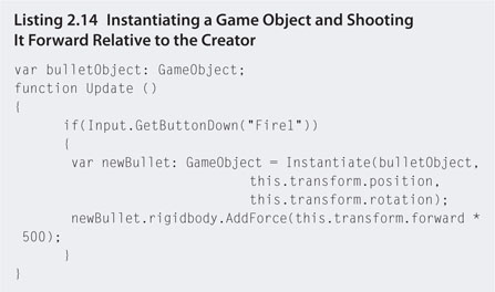
Step 14. Create a JavaScript file and call it fire. Add the script from Listing 2.14.
Step 15. Save fire.js and attach it to the Main Camera, which is part of the FPC in the Hierarchy. Select the FPC Main Camera in the Hierarchy and drag and drop the bullet prefab from the Project onto the exposed bulletObject variable in the fire.js script as shown in Figure 2.37.
Step 16. Save and play. The right mouse button, called “Fire1” in the script, will instantiate copies of the bullet prefab and add a force with the same direction as the camera. To change the speed of the bullets, modify the force multiplier in fire.js.
![]() Note
Note
If an object is moving too fast, Unity can sometimes miss the collision event and it will go through walls and floors. If this happens, try slowing the object down or making its collision component bigger. Also note that Unity will not register collisions between two complex mesh objects. If you have a mesh object that is not colliding, think of replacing its collider with a simple sphere or box collider. To do this, click on the object in the Hierarchy and select a new physics collider from the main menu.
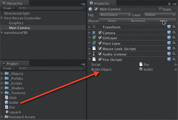
FIG 2.37 Setting a script variable to the value of a prefab object.
Step 17. We are now going to create sticky bullets. Open the blob.js file. Enter the script from Listing 2.15
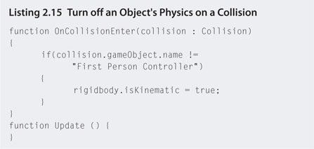
Step 18. Save and play. You will have created sticky bullets that stop moving the instance they collide with something. The isKinematic setting in the script will turn off physics effects on the object when it is set to true. A test is performed to check if the object has hit the FPC before it turns off the physics. This is used to ensure that the bullets don't stick to the FPC.
Step 19. Finally, to make the bullet object squash when it hits the wall, modify your script to that in Listing 2.16.
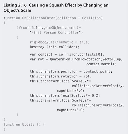
Step 20. Save and play. The code now destroys the collider component to stop the FPC from hitting the stationary bullets. If you take this line out you will notice that the bullets create barriers the FPC collides with. Data are taken from the collision and used to rotate the object just as the y axis is aligned with the normal of the point of contact. This means that when the y axis is scaled down, the object presses flat to the object it collided with. The x and z scales can then be resized based on the collision velocity to create a bigger splat.
Step 21. Create a shiny black material for the bullet prefab, and take a walk around the warehouse, leaving blobs everywhere. Note that funny unaligned blobs will be caused by collisions with other complex meshes, such as chairs. This code works best with walls, floors, and other large flat areas.
A simple implementation of anticipation is seen in racing games. At the beginning of a race, a traffic light or countdown will display, giving the player a heads up to when the race is about to start. Another way to add anticipation is to have explosive devices with countdown timers. In Splinter Cell, for example, the lead character, Sam Fisher, may lay down explosive charges and then a countdown occurs before they explode.
![]() Unity Hands On
Unity Hands On
Anticipation
Step 1. Open the project from the last hands-on session or download and open Chapter Two/AnimPrinciplesA.zip. We are now going to make the sticky bullets into timed explosive devices.
Step 2. Download Chapter Two/Detonater.unityPackage and import into your project, Assets > Import Package > Custom Package.
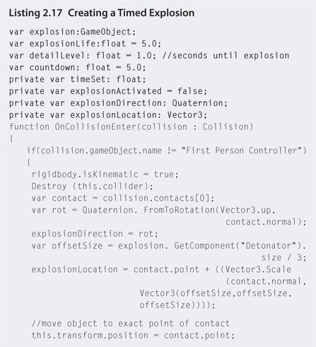
Step 3. Open blob.js and modify the code to that in Listing 2.17.
Step 4. Click on the bullet prefab in the Project. Find the Explosion property of the blob script and set it to Detonator-Insanity. You can find this by clicking on the little circle next to the property field or drag and drop this prefab from the Project. It can be found in Standard Assets > Detonator > Prefab Examples.
Step 5. Save and play. Drop a sticky bullet somewhere and stand back and watch.
Follow-through refers to actions occurring after and as a result of another action. For example, in racing games, a common follow-through is when one car clips another car and it goes spinning out of control. In most games where you have to blow something up there is bound to be a follow-through action that removes obstacles from the player's game progression.
![]() Unity Hands On
Unity Hands On
Follow-Through
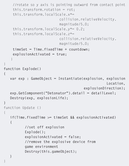
Step 1. Open the project from the last hands-on session or download and open Chapter Two/AnimPrinciplesB.zip. We are now going to add a door that can be blown up with the timed explosive devices. Create a cube and modify its scale, rotation, and position as necessary to have it fit one of the doorways in the warehouse as shown in Figure 2.38. Rename the cube “Door.”
FIG 2.38 A Cube used as a door.
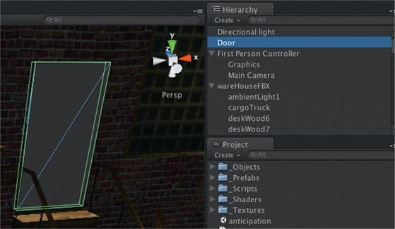
Step 2. Open blob.js and modify as shown in Listing 2.18.
Step 3. Save and play. Position a sticky explosive on the door and watch as it gets destroyed.
Step 4. Create more cubes to fit in the other doorways. Ensure that they are named “Door” in the Hierarchy and any sticky explosive will destroy them. If you want to blow up anything the sticky bullet is stuck to, remove the if statement testing for just “Doors” (and the associated {} )! Be careful though, you might fall through the floor if you destroy the wrong object.
Secondary Motion
Secondary motion brings the game environment to life. The simplest of movements can hint at a dynamic realistic environment with a life of its own. For example, a swaying tree or moving grass provides the illusion of a light breeze while also suggesting to the player that these are living things. How often have you been for a walk in a forest that doesn't move around you? Even in a still warehouse environment there is the opportunity to add secondary motion to add extra atmosphere to the scene.
Secondary Motion
Step 1. Open the project from the last hands-on session or download and open Chapter Two/AnimPrinciplesC.zip. We are going to add some curtains and wind effects reminiscent of morgue scenes from the original Splinter Cell.
Step 2. In the Scene, move your point of view such that you are looking into the room that has the truck in it. Add a cloth object by selecting GameObject > Cloth from the main menu.
Step 3. Rotate, resize, and position the cloth in the doorway as shown in Figure 2.39 . Ensure that the cloth does not touch any sides or the top or bottom of the doorway. Rotate it with the normal facing outward (away from the truck). You will notice that the cloth object, just like a plane, only has one side. It will not be visible from inside the other room.
FIG 2.39 Positioning a cloth object in a doorway with attachments.
Step 4. Create a new material and add it to the cloth. Set the shader to Transparent/VertexLit. Make up your own Main Color (and set the alpha value to 80% for some transparency), Spec Color (this is the color that is reflected from the surface when lit), and Emissive Color (this is the glow color). Select a texture. In this example, the innerWindow texture is used with the x and y tiling values set to 10 each.
Step 5. Create a cube. If you cannot see it, with the cube selected in the Hierarchy, select GameObject > Move to View from the main menu. The cube will move to the center of the Scene view.
Step 6. Position the cube at the top left of the cloth. The cloth must appear as though it is inserted into the side of the cube as shown in Figure 2.39. . Create another cube and position it at the top right of the cloth. Rename the cubes, ClothHook1 and ClothHook2. It doesn't matter which one is which.
Step 7. Select the cloth in the Hierarchy and locate the Interactive Cloth component in the Inspector. Change the size for the Attached Colliders section to 2. Set the colliders for Element 0 to ClothHook1 and Element 1 to ClothHook2 as shown in Figure 2.39.
Step 8. Play. Note that the cloth becomes limp and hangs from the two cubes like a curtain. If the cloth falls to the ground or hangs from only one cube, it will be because the cubes do not intersect with the cloth in the corners.
Step 9. While still playing and watching in the Scene, select the cloth and locate the Interactive Cloth component in the Inspector. To add a blowing effect to the cloth, change the values of x, y, and z for the External Acceleration and Random Acceleration values. External Acceleration will add a constant fan like blowing force and Random Acceleration will randomly add puff like breezes to the cloth. It is a matter of playing around with these values to get the effect you want. Remember that while you are in play mode, any of the changes made to the cloth settings will revert when you stop. Note the values you would like to keep to reenter them once you are out of play mode.
Step 10. In the Hierarchy, drag and drop both ClothHook objects onto the InteractiveCloth object to make them child objects and attach them to the cloth.
Step 11. Press play and take your FPC through the cloth. Once inside the truck room, turn to look back at the cloth. It will not be visible because the normal is the other way around. The easiest way to fix this is to create another cloth object exactly the same and flip it around to face into the truck room.
Step 12. Right-click on the InteractiveCloth in the Hierarchy and select Duplicate. Two cloths will now appear in the Hierarchy. Rename them Cloth1 and Cloth2.
Step 13. Select Cloth2 and rotate it 90° such that its normal is pointing into the room with the truck.
Step 14. Play. This time you will be able to take the FPC back and forth between the rooms and see the cloth from both sides.
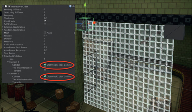
Interactive Cloth
For more information on the settings for cloth, check out
http://unity3d.com/support/documentation/Components/classInteractiveCloth.html.
2.7 Two-Dimensional and 3D Tricks for Optimizing Game Space
The real world is a big place. The dream of many a game designer is to recreate the real world in all its detailed glory and vastness. Unfortunately, modeling everything down to the last nut and bolt and putting it into a game engine for real-time processing is not possible. However, many games do fake the vastness of the outside world very effectively, fooling the player into believing that the environment outside the game play area goes on forever.
A game requires a high frame rate to provide the player with a seamless game-playing experience. Between each frame, the computer must process all game object behavior, sound, physics, and player interactions. The number of game objects in view of the game has a large effect on the frame rate as they must be processed and re-rendered. Therefore, when designing a game level or environment it is critical to keep in mind how many things will need to be drawn in a scene and reduce this to an absolute minimum while keeping the quality high. Having said this, it might not necessarily be the number of objects in a scene that need to be reduced but reconsideration of how they are treated and drawn.
This section explores some common ways for optimizing 3D game worlds.
2.7.1 Reducing Polygons
Each polygon, being the smallest part of a mesh, adds to the processing of a scene. On high-end gaming machines the polycount must increase dramatically to affect the frame rate. However, on mobile devices, simply adding a couple of hundred polygons can bring a game to a halt. Here are some methods to reduce the polycount.
Use Only What You Need
When creating a model for a game, consider the number of superfluous polygons in the mesh and reduce. For example, the default plane object created by Unity is essentially a square. If you only ever use it as a square, such as for objects in the rocket ship game, this object is inefficient as it has many polygons. A simple square plane only requires two triangular polygons. In this case, create a square plane in Blender and import it instead.
As discovered earlier, Unity does not show the reverse side of surfaces. This is called backface culling and is a common technique in computer graphics for not drawing the reverse side of a polygon. In some cases, however, as with the curtain in the warehouse example, it may be necessary to draw both sides. In the hands-on session we used two cloths, one for either side. This is an inefficient way as it immediately doubles the number of polygons used for the curtain. A better way is to turn backface culling off.
To do this in Unity requires the writing of a shader. A shader is a piece of code the game engine interprets as a texturing treatment for the surface of a polygon. When you set a material to Diffuse or Transparent/Specular, you are using a prewritten shader.
To write your own shader requires extensive knowledge of the shader language and complex computer graphics principles; however, numerous shaders are available on the Unity Web site for you to try, so here are the steps required to add a custom shader.
![]() Unity Hands On
Unity Hands On
Loading a Custom Shader
Step 1. Open Unity and create a simple scene with plane or other object to test the shader. If you prefer, you could add this to the curtain in the warehouse application.
Step 2. In the Project select Create > Shader. A new shader file will appear in the Project. Rename to backfaceOn. Double-click to open this file. Replace the existing code with that in Listing 2.19. This custom shader has been taken from http://unity3d.com/support/documentation/Components/SL-CullAndDepth.html.
Step 3. Drag and drop the shader into Unity's Project view.
Step 4. Create a new material. In the shader drop-down selection box your new shader will be available as Backface On. You can now use the material like any other.
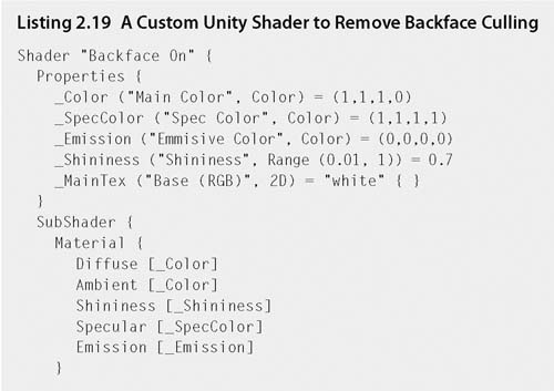
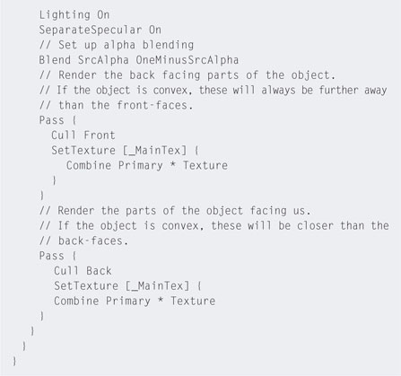
Level of Detail
Level of detail (LOD) is a technique for providing multiple models and textures for a single object with reducing levels of detail. For example, you may have a high polycount, high-resolution textured model, a medium polycount, medium-resolution textured model, and a low polycount, low-resolution texture model for a single character. The model that gets drawn by the renderer will depend on the distance the camera is away from the character. If the character is close, the highest quality version is used. If the character is far in the distance, the lowest quality version is used.
This method not only mimics human vision-making objects in the distance less defined, but also allows for the drawing of more objects in a scene as the ones farther away take up less memory.
![]() Unity Hands On
Unity Hands On
A Simple LOD Handler
Step 1. Download Chapter Two/LOD.zip from the Web site, unzip, and open in Unity. In the Project, double-click on lodbuilding of the Scenes folder to open the scene. The Scene will appear with a high-rise building and FPC.
Step 2. Play. Move around using the FPC controls.
Step 3. While playing, in the Game, click on the Stats button at the top right of the Game tab as shown in Figure 2.40. A window with game statistics will display as an overlay. In this window you can see how fast the application is running and how many triangles (a.k.a. polygons) are in the camera view.
FIG 2.40 The Stats button in the Game tab displays current game performance values.
Step 4. Stop playing and create a new JavaScript file called LODManager. Add the code shown in Listing 2.20.
Step 5. Save the code. Attach it to the Building object in the Hierarchy. Select Building in the Hierarchy and locate the LOD Manager script component in the Inspector.
Step 6. Click on the small circle to select a mesh for the value of Lod 1. When the pop-up selector opens you will find two building meshes. Select the one with more detail.
Step 7. Set the value for Lod 2 the same way, except this time pick the less detailed building mesh.
Step 8. Set Lod Dist 1 to 80 and Lod Dist 2 to 120.
Step 9. Play. Turn around to face the building. Remain facing the building as you move backward by holding the down arrow key. When you get a distance of 80 away from the building the mesh will switch to the less detailed mesh. Move forward again and as you pass the 80 threshold it will become more detailed. Watch the Stats screen polycount change as you move back and forth. Now move even farther back. When you pass a distance of 120 the building will disappear because in the script it is set to “null” or not value after Lod Dist 2.
Step 10. Duplicate the Building object and move the copies around on the terrain to create a bigger city. Walk around it observing how the LOD snaps buildings in and out of different levels of detail.
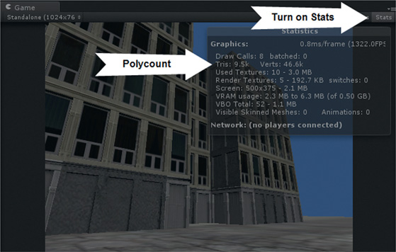
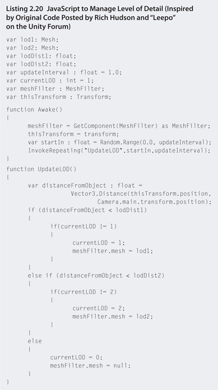
What you have just experienced is a very simple implementation of LOD. It works well to reduce the polycount and yet keep many objects in the scene, giving a great depth to the environment. You may have experienced this snapping effect in games you have played.
2.7.2 Camera Viewing Volume
Previously in this chapter we examined the camera viewing volume and how it reduces the objects being drawn. To emphasize its effectiveness in association with LOD, we will run through a quick example.
![]() Unity Hands On
Unity Hands On
Camera Viewing Volume and LOD
Step 1. Using the project from the previous hands-on session, create a prefab from the Building object and remove any others from the surface of the terrain.
Step 2. Create a new JavaScript file called instantCity and add the code in Listing 2.21.
Step 3. Save the script and attach it to the First Person Controller. Click on the FPC and locate the script component in the Hierarchy. Drag and Drop the building prefab from the Project onto the building property of the script in the Inspector. In LOD Manager change the LOD Dist 1 to 500 and LOD Dist 2 to 1000.
Step 4. Play with both the Scene and the Game open. Orient your view in the Scene to be looking down on the terrain. When you first play the game note that all the buildings are created and positioned by the instantCity script. After this, buildings that are a certain distance from the FPC are removed. This is the LOD script in action. You can modify the distance values for the buildings LOD in the Inspector for the building prefab. In the Scene you will also see the FPC frustum. If it is larger than the range of the drawn buildings then it is too large.
Step 5. While playing, stand in one location and look around in the Game. How far can you see? If you can't see the buildings at the edge of the frustum, the far plane setting for the camera is too large. Try reducing it to see if it will have any effect on the environment. Remember, if you can't see a game object, there is no reason to try to draw it.
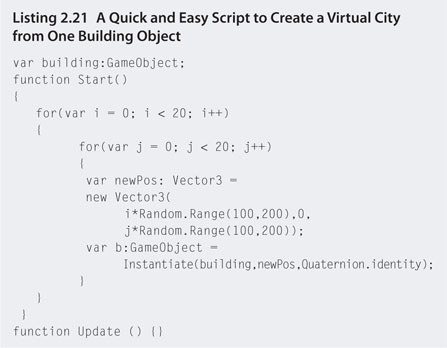
2.7.3 Fog
Another very (very) handy trick in reducing the visual size of a game environment is fog. In the previous examples when the FPC was at a far enough distance from the buildings they would slide behind the far plane of the camera or snap out of view because of the LOD. By adding fog, these other rather too obvious techniques can be hidden. A layer of fog can be added just before the far plane of the camera or the farthest distance of the LOD.
![]() Unity Hands On
Unity Hands On
Fog
Step 1. Open the project from the last hands-on session.
Step 2. Select Edit > Render Settings from the main menu.
Step 3. Tick the Fog box now available in the Inspector. Note that a gray fog covers the ground but not the sky in the Game.
Step 4. Play. Walk around the city. Buildings in the distance will be completely fogged out. As you move closer to a building the fog will lift.
Step 5. The thickness of the fog is modified in the Fog Density property of render settings. You will notice in the same place that you can change the color of the fog. The issue now faced is that the ground and buildings are fogged over, but the background color is not. This is a fact of life with using fog, as fog is only applied to game objects and not to the background. The best way to overcome this is to set the background color to the same color as the fog. This makes for a very convincing cloudy sky.
Step 6. Select the color picker for the fog and select a color. Note down the RGB and A values.
Step 7. In the Hierarchy, select the Main Camera attached to the FPC. Change the background color in the Inspector to the same color as the fog.
Step 8. Set the fog density to 0.005.
Step 9. Play. At this point it becomes a fine balance of testing if in the distance you can still see buildings disappearing instead of blurring into the fog. If so, try turning up the fog a little.
2.7.4 Textures
Fine-detailed, high-quality textures are the best defense against high polycounts. There is far more detail in a photorealistic image of a real-world item than could possibly fit into the polycount restrictions of any real-time game engine. Chapter One examined briefly the use of normal and specular maps to give extra texturing to game objects. Here we discuss two more popular tricks.
When creating materials in Unity you may have seen properties for x and y offsets. These values are used to adjust the alignment and location of a texture on a polygon's surface. If these values are adjusted constantly with each game loop, the texture will appear animated. This is an effective way of creating an animation that doesn't involve modeling or extra polygons. It is often used in creating sky and water effects.
![]() Unity Hands On
Unity Hands On
Animated Textures
Step 1. Create a new Unity project.
Step 2. In the Scene add a plane.
Step 3. Create a new material and add it to the plane.
Step 4. Find a seamless texture of your choosing from the Web.
Step 5. Drag and drop the new texture into the Project.
Step 6. Add the texture to the material. It should appear on the surface of the plane.
Step 7. Create a new JavaScript file called animatedTexture. Add the code in Listing 2.22.
Step 8. Attach the JavaScript to the plane.
Step 9. Play. The texture will move across the surface of the plane. To change the direction of the movement, modify the x and y values for the uvSpeed variable in the script. The LateUpDate() function is similar to the Update() function in that it executes for an object every game loop. However, with LateUpDate() it occurs as the very last function called for an object so that it can take into consideration any related processing occurring in the same game loop.
Step 10. Open the project with the warehouse. Create a new JavaScript file and enter the same code from Listing 2.22. Attach this script to polySurface437. This is the surface of the conveyor belt in the room where you placed the curtain. Play and watch the conveyor move!

Shadows give a scene an extra dimension of depth and add to visual realism. Generating shadows is processor intensive. Although shadows in game environments are covered in Chapter Seven, a quick and easy method for generating processor light shadows called Blob Shadows is introduced here.
Usually the game rendering system calculates shadows based on the position and intensity of lights and the position of game objects. When many realtime shadows need to be calculated, such as those of moving objects, such as characters, it can slow the frame rate considerably. This is a big problem for games on mobile devices where such shadowing is not practical.
![]() Unity Hands On
Unity Hands On
Blob Shadows
Step 1. Download Chapter Two/BlobShadows.zip from the Web site, unzip, and open in Unity. In the Project, double-click on blobshadowexamples of the Scenes folder to open the scene. The Scene will appear with a character standing on a plane.
Step 2. Select Assets > Import Package > Projectors from the main menu to import the projector package.
Step 3. Locate Blob Shadow Projector in the Project and drag and drop it onto the Male game object. A frustum object will appear under the Male model. This is the Blob Shadow Projector.
Step 4. Move the projector up until it is just above the top of the model's head. A black blob will appear on the ground. This is the blob shadow. The shadow is created using a material with the texture of the round black blob on it. When the projector intersects a plane, as it does here with the ground, the black texture is drawn inside the intersection area of the plane and the projector frustum.
Step 5. In its current state the Male model is also inside the projector frustum and therefore the shadow is drawn on it too. To fix this we place the model into another drawing layer. Select the Male object in the Hierarchy. In the Inspector at the very top to the right of Tag is a property called Layer. Click on the drop-down box next to Layer and select Add Layer.
Step 6. In the Tag Manager that opens in the Inspector, next to User Layer 8, type in character. This will create a new drawing layer called character.
Step 7. Select the Male object in the Hierarchy again. In the Inspector, set its Layer to character using the drop-down box.
Step 8. Select the Blob Shadow Projector in the Hierarchy. In the Inspector's Projector Component, set the Ignore Layers property to character. The projector will now ignore anything in the character layer, which in this case is the Male model, and draw the shadow object everywhere else it intersects.
This is a very effective way to add convincing shadows to objects without adding too much processing overhead.
2.7.5 Billboards
Billboarding is a technique that uses planes to fake a lot of background scenery. A billboard is a plane usually having a partially transparent texture applied to give it the appearance of being a shape other than a square. Common uses for billboards are grass, clouds, and distant trees.
To give the illusion that the billboard is viewable from all angles, the plane orientates itself constantly so that it is always facing the player.
![]() Unity Hands On
Unity Hands On
Billboards
Step 1. Open a new Unity project and add a ground plane and an FPC (for which you will need to import the Character Controller package).
Step 2. Download Chapter Two/basicPlane.blend and grass.psd from the Web site and add to your project.
Step 3. Add a Directional Light game object and rotate it down to give some shading to the ground plane.
Step 4. Add the basicPlane to the Scene and rotate it by −90° around the x axis to make it stand upright. If you can't see the surface after rotating, orient your view so that you are on the other side of the plane.
Step 5. Create a new material called grass. Set the shader to Transparent/Diffuse. Use the previously downloaded grass texture on it.
Step 6. Add this material to the basicPlane object. It will need to be dragged and dropped onto the Plane child object that is attached to basicPlane as this holds the mesh.
Step 7. Play. Walk around the scene with the FPC and examine the plane. From a distance it looks good. As you approach it and move around, it becomes apparent that the image is flat and not viewable from the underside.
Step 8. To update the plane so that it always faces the player, create a new JavaScript file called billboard and attach it to the basicPlane. Enter the code in Listing 2.23.
Step 9. Play. The plane will always face the player. If the grass texture appears upside down on the plane, set the y tiling value to −1 in the material.
Step 10. To see the full effect, duplicate the basicPlane object four or five times and move them around to create a bunch of grass. Play and walk around.
Step 11. When you walk over the top of the grass it will lay down flat. If the billboard were a tree you wouldn't want this to happen. Rather, rotating around the x axis should be turned off. That way the object will stay vertical and only turn around its y axis. To allow for this, modify billboard.js to the code in Listing 2.24.
Step 12. Play. The grass will not bend over as the FPC approaches it. You can now turn this feature on and off using the tick box for StayUpright in the Inspector when billboard.js is attached to a game object.
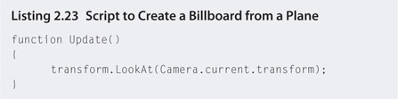
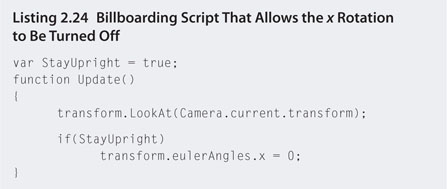
More often than not, billboards are used on horizon lines and in the distance. Because they do not stand up under close scrutiny, you may want to use them on mass, but in areas of the game environment the player can't quite reach.
2.8 Summary
This chapter covered a variety of techniques for replicating real-world mechanics in a game environment. These have included movement with vectors and the physics system and optimization techniques that make the virtual world seem as extensive as the real world.
Most often satisfactory movement in a game environment can be achieved through knowledge of vector mathematics. Applying this first before jumping headlong into the physics system will optimize processing of the game environment. For example, in the rocket ship hands-on session, physics could have been employed to push the rocket ship around the planet. This would, however, have been overkill, as only a simple translation and slerping algorithm was required.
It is a common first-timer mistake when creating a game environment to make it detailed and vast without consideration for how game play will be affected as the frame rate drops. Many cannot understand how such topquality AAA titles can run so fast with such intricate landscapes and mindblowing special effects, and it is often the game engine that takes the blame. This is not the case, and this chapter has revealed some of the tricks employed by professionals to trick the player's perception of the environment.
1 This is only for a land map. For 3D coordinates, there are no such equivalents.
2 Earth's actual gravitational acceleration.
3 This is acceleration due to gravity on earth.