
Configuring the VPN Server
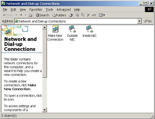
Make sure that your outside NIC is configured with a valid IP address, as assigned by your ISP. This could be a static or dynamically assigned IP address. Also, check to be sure that your inside NIC is configured with a nonroutable private IP address such as 192.168.x.x, 10.x.x.x, or 172.16.x.x-172.31.x.x. (See RFC 1918 for more information about private IP addresses.) The inside NIC is generally given a static IP address. Figure 8.1 illustrates network and dial-up connections.
Figure 8.1. Network and dial-up connections.
Tip
Remember to always keep your operating system up to date with all the most current patches and system updates. For Windows machines, point your web browser to http://windowsupdate.microsoft.com. |
By default, a Windows 2000 machine will not forward packets between the inside and outside NICs. To turn your box into a VPN server, you must install the Routing and Remote Access Service (RRAS). Click Start | Programs | Administrative Tools | Routing and Remote Access.
You should see your local machine in the left frame (Figure 8.2). Do a right mouse click on your machine, and click Configure and Enable Routing and Remote Access. This will launch a very handy wizard to walk you through all of the installation options (Figure 8.3).
Figure 8.2. The routing and remote access snap-in.

Figure 8.3. The routing and remote access server setup wizard.

Manually Configured Server
First you will see a welcome screen. Click Next. Then, select Manually Configured Server and click Next. Click Yes when asked if you want to start the service.
By default, the following things will happen:
Five virtual PPTP ports and five virtual L2TP ports will be enabled.
A DHCP relay agent will be enabled.
Client authentication will be based on Windows authentication (not RADIUS) using MS-CHAP and MS-CHAP v2.
A remote access policy exists which, in effect, denies all remote access.
A new icon, called Incoming Connections, will appear in your Network and Dialup-Connections folder (Figure 8.4).
Figure 8.4. A new icon appears in the network and dial-up connections setup screen.

If you go back to the Routing and Remote Access menu (Click Start | Programs | Administrative Tools | Routing and Remote Access) and click on your local server, you will see a variety of new configuration options.
First we must decide how to hand out IP addresses to our VPN clients. If you have a DHCP server in your inside LAN, you don't have to do anything. If you don't have a DHCP server, you should manually assign a pool of IP addresses. You may wish to manually assign a pool of IP addresses even if you have a DHCP server, just for administrative ease to visually separate your VPN clients from your other clients.
To create a pool of IP addresses, right-click on your local machine in the RRAS snap-in and click Properties | the IP tab | Static Address Pool | Add. Select a Start IP and End IP address to match your inside NIC address. For example, if your inside IP address is 192.168.5.1 (subnet 255.255.0.0), select an arbitrary start IP address, such as 192.168.255.1 and an end IP address of 192.168.255.254. Note that the Use the following adapter to obtain DHCP, DNS, and WINS addresses for dial-up clients should be set to Adapter: Inside NIC.
Configuring Static Routes
Next, configure the static routes for your network. By using static routes, you will avoid having to configure dynamic routing protocols such as RIP or OSPF. Basically, you need to configure two routes: One to tell the inside NIC how to see the outside world, the other to tell the outside NIC how to see the inside world.
To configure the first static route (Figure 8.5), launch the RRAS snap-in, click on your local server, then click IP Routing. Right-click Static Routes and select New Static Route. On the Inside NIC interface, my IP address is 192.168.5.1. Therefore, I am using a Destination of 192.168.0.0 with a subnet mask of 255.255.0.0. For the gateway, if this is a simple network and all the intranet machines are in the same subnet, no router is needed and you can use your NIC's IP as the gateway (i.e., 192.168.5.1). However, in a complex environment, the gateway should point to your intranet router. You may need several static route entries (one for each subnet's router in your internal network).
Figure 8.5. Configuring the 'inside' static route.

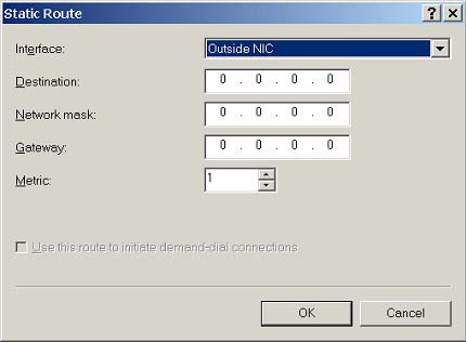
For the second static route (Figure 8.6), configure the Outside NIC with a destination, mask, and gateway of 0.0.0.0.
Figure 8.6. Configuring the 'outside' static route.
Increase PPTP and L2TP Ports
The next step is to increase the number of PPTP and L2TP ports. As mentioned earlier, by default Windows 2000 will create five PPTP ports and five L2TP ports when you select Manually Configured Server. Again, in the RRAS snap-in, click on your local server, then right-click on Ports and click Properties | WAN Miniport (PPTP) | Configure. Change the Maximum ports as needed (e.g., to 200). Repeat this step for WAN Miniport (L2TP).
Create VPN Filters
The steps in the section create filters to ensure that the VPN server allows only sending and receiving VPN traffic on the outside NIC. All other traffic should be blocked. Since we have turned on IP Routing, if we don't establish filters, all traffic, malicious or not, will be forwarded. This risk is mitigated if the VPN server is protected by a firewall; however, if the VPN server is sitting unprotected, out on the Internet, then additional filters are absolutely needed.
Here's how to set it up for PPTP: Launch the RRAS snap-in, click on the local server, and then select IP Routing | General. In the right frame, right-click on the Outside NIC and select Properties (Figure 8.7).
Figure 8.7. Outside NEC properties.

On the General tab, click Input Filters | Add | Destination network checkbox. For IP Address, use the address for the Outside NIC. (This is the address given to you by your ISP). For Subnet mask, use 255.255.255.255. For Protocol, select Other and type 47 as the Protocol number. Click OK.
While you're still in the Input Filters dialogue box, again click Add (Figure 8.8). Click Destination network. For IP Address use the address for the Outside NIC (provided by your ISP). For Subnet mask use 255.255.255.255. For Protocol, select TCP (not TCP [established]) and type 1723 as the Destination port. Click OK.
Figure 8.8. Input filters dialog box.

While you're still in the Input Filters dialogue box, click Add one more time. Click Destination network. For IP Address use the address for the Outside NIC (provided by your ISP). For Subnet mask use 255.255.255.255. For Protocol select TCP [established] and type 1723 as the Source port. Click OK. Select Drop all packets except those that meet the criteria below and click OK again.
While you're still in the Outside NIC Properties, click Output Filters | Add | Source Network. For IP Address use the address for the Outside NIC (provided by your ISP). For Subnet mask use 255.255.255.255. For Protocol select Other and type 47 as the Protocol number. Click OK.
While you're still in the Output Filters dialogue box, click Add | Source network. For IP Address use the address for the Outside NIC (provided by your ISP). For Subnet mask use 255.255.255.255. For Protocol select TCP and type 1723 as the Source port. Click OK. Click Add one more time. Select Source Network. For IP Address use the address for the Outside NIC (provided by your ISP). For Subnet mask use 255.255.255.255. For Protocol select TCP [established] and type 1723 as the Destination port. Click OK. Select Drop all packets except those that meet the criteria below and click OK again. Click OK to save your changes to the Outside NIC Properties.
To set up a filter for L2TP, we will follow a similar procedure:
Launch the RRAS snap-in, click on the local server | IP Routing | General. In the right frame, right-click on Outside NIC and select Properties. On the General tab, click Input Filters | Add | Destination network checkbox. For IP Address, use the address for the Outside NIC. (This is the address given to you by your ISP.) For Subnet mask use 255.255.255.255. For Protocol select UDP and type 500 for both the Source port and the Destination port. Click OK.
While you're still in the Input Filters dialogue box, click Add | Destination network. For IP Address use the address for the Outside NIC (provided by your ISP). For Subnet mask use 255.255.255.255. For Protocol select UDP and type 1701 for both the Source port and the Destination port. Click OK. Select Drop all packets except those that meet the criteria below and click OK again.
While you're still in the Outside NIC Properties, click Output Filters | Add | Select Source Network. For IP Address use the address for the Outside NIC (provided by your ISP). For Subnet mask use 255.255.255.255. For Protocol select UDP and type 500 for both the Source port and the Destination port. Click OK.
While you're still in the Output Filters dialogue box, click Add | Source network. For IP Address use the address for the Outside NIC (provided by your ISP). For Subnet mask use 255.255.255.255. For Protocol select UDP and type 1701 for both the Source port and the Destination port. Click OK. Select Drop all packets except those that meet the criteria below and click OK again. Click OK to save your changes to the Outside NIC Properties.
Figures 8.9 and 8.10 show the completed input and output filters.
Figure 8.9. Completed input filters.
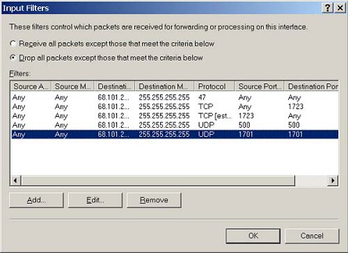
Figure 8.10. Completed output filters.

Assign a Phone Number
Next, we need to configure the phone number for the PPTP and L2TP devices. This is done to make life easier when we are configuring our remote access policies. Obviously, VPNs do not have phone numbers, therefore we use IP addresses. Here's how to do it: Launch the RRAS snap-in, click on the local server and then right-click Ports and click Properties | WAN Miniport (PPTP) | Configure. Set the phone number for this device as the IP address for the Outside NIC (provided by your ISP). Repeat this step for WAN Miniport (L2TP).
Establishing VPN policies
At this point, our Windows 2000 Server machine is configured to only allow VPN traffic to pass between its two interfaces. Our next task is to configure policies to give VPN permission to users. In general, it is recommended to apply a least privilege policy when assigning rights, meaning that VPN access should only be given to those users who require it to perform their job responsibilities. Rights can be assigned on a per-user basis or on a remote access policy basis.
I recommend putting users into groups (say, VPN Users) and then using remote access policies to control access for everybody. You will notice in the Computer Management Snap-In that each user's properties includes a Dial-in tab (Figure 8.11) which includes a Remote Access Permission section with a default selection of Control access through Remote Access Policy. For each user who will need VPN access, confirm that their dial-in properties are set for Control access through Remote Access Policy.
Figure 8.11. 'Dial-in' tab for a user.

Next, in the RRAS snap-in, click on the local server and then right-click on Remote Access Policies and select New Remote Access Policy. This step is illustrated in Figure 8.12.
Figure 8.12. Adding a remote access policy.

Set the Policy friendly name to Remote Access for VPN Clients and add these conditions:
Nas-Port-Type = Virtual (VPN)
Windows-Groups = VPN Users (or whatever you named your group)
Called-Station-ID = the IP address for the Outside NIC (provided by your ISP).
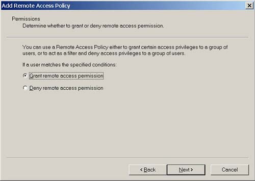
Set permission to Grant remote access permission (Figure 8.13).
Figure 8.13. Grant remote access permission.
Set the Profile settings:
In the Authentication tab, select Extensible Authentication Protocol.
In the Encryption tab, select only Strong and Strongest.
Note that if this is your first time configuring your remote access policies, you may have a default policy configured called Allow access if dial-in permission is enabled. Make sure you delete this policy.