

Combining local and metro continuous availability with out-of-region disaster recovery
In this chapter, we discuss the capabilities and considerations for implementing GDPS Metro Global - GM (GDPS MGM) and GDPS Metro Global - XRC (GDPS MzGM). It is of interest to clients who have requirements for both continuous availability locally and regional disaster recovery protection.
GDPS MGM and GDPS MzGM combine the continuous availability attributes of GDPS Metro, or GDPS Metro HyperSwap Manager with the out-of-region disaster recovery capabilities of GDPS Global - GM or GDPS Global - XRC to protect critical business data during a wide-scale disruption. They also provide for fast automated recovery under various failure conditions.
|
Note: GDPS Metro and GDPS Metro HyperSwap Manager can be combined with GDPS GM or GDPS XRC, as described in this chapter. To aid in readability, only GDPS Metro is used in the text for most of the descriptions. If a particular function is not supported by GDPS Metro HyperSwap Manager, it is specifically mentioned.
|
The following functions are provided by GDPS MGM and GDPS MzGM:
•Three-copy disk mirroring using GDPS Metro to support zero data loss for day-to-day disruptions at metropolitan distances, and GDPS GM or GDPS XRC for long distance, out-of-region data protection, with limited data loss during a wide-scale disruption.
•Four-copy1 disk mirroring combining GDPS Metro in the production region to support zero data loss for day-to-day disruptions at metropolitan distances, GDPS GM or GDPS XRC between the two regions, and another instance of GDPS Metro in the recovery region to manage Global Copy (PPRC-XD) that can be switched to synchronous-mode while moving production to the recovery region in a planned or unplanned manner.
•Multisite management of the remote copy environment to maintain data integrity and data consistency across all disk copies.
•Support for transparent switching to secondary disks if there is a primary disk storage subsystem failure by using GDPS Metro with HyperSwap.
This support offers the ability to incrementally resynchronize the GDPS GM or GDPS XRC mirror after a Metro Mirror HyperSwap.
•Fast, automated recovery for recovery time objective (RTO) of less than an hour for site and regional disasters.
•Zero data loss protection for both open systems and IBM Z systems by using GDPS Metro and GDPS GM, assuming that only one site is lost during a disaster.
•Use of FlashCopy to facilitate nondisruptive functions (such as backups, data mining, application testing, disaster recovery testing), and to provide a consistent copy of the data during remote copy synchronization to ensure disaster readiness is maintained at all times.
•Planned switch to run production in the recovery region and then return home.
This chapter includes the following topics:
9.1 Introduction
Enterprises running highly critical applications have an increasing need to improve the overall resilience of their business services and functions. Enterprises already doing synchronous replication have become accustomed to the availability benefits of relatively short distance synchronous replication. This is especially true in mainframe environments where the capabilities of HyperSwap provide the ability to handle disk subsystem failures without an outage and to use server capacity in both sites.
Regulatory bodies (both governmental and industry-based) in various countries are requiring enterprises to maintain a significant distance between their primary and disaster locations to protect against wide-scale disruptions. For some organizations, this can result in a requirement to establish backup facilities well outside the range of synchronous replication capabilities, thus driving the need to implement asynchronous disk mirroring solutions.
From a business perspective, this could mean compromising continuous availability to comply with regulatory requirements. With a three-copy disk mirroring solution, the availability benefits of synchronous replication can be combined with the distance allowed by asynchronous replication to meet both the availability expectations of the business and the requirements of the regulator. Further extension to four-copy configurations allows for equivalent high availability characteristics when running in either region.
9.2 Design considerations
In the following sections we describe design considerations including three-copy solutions versus 3-site solutions, multi-target and cascading topologies, four-copy solutions, and cost considerations.
9.2.1 Three-copy solutions versus 3-site solutions
It is not always the case that clients implementing a three-copy mirroring solution will have three independent data centers (as shown in Figure 9-1), each with the capability to run production workloads.
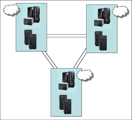
Figure 9-1 Three-site solution
Having three distinct locations with both the connectivity required for the replication and connectivity for user access is expensive and might not provide sufficient cost justification. As the distance between the locations connected with synchronous mirroring increases, the ability to provide continuous availability features such as cross-site disk access, HyperSwap, or CF duplexing diminishes.
Having a production location with two copies of data within a single data center (shown in Figure 9-2), along with a third copy of the data at a remote recovery location, provides you with many of the benefits of a full 3-site solution while allowing for a reduced overall cost. Disk subsystem failures are handled as local failures and if the single site has some degree of internal resilience, then even minor “disaster-type” events can perhaps be handled within the single location.
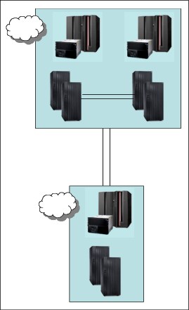
Figure 9-2 A 2-site solution
Another benefit of the two-data center solution, especially in an IBM Z environment, is that you can realize the full benefit of features such as HyperSwap and coupling facility duplexing to provide continuous availability features without provisioning significant additional and expensive cross-site connectivity, or having concerns regarding the impact of extended distance on production workloads.
Figure 9-3 shows another variation of this scenario, in which the primary data center is a campus location with separate machine rooms or buildings, each with the ability to run production workloads.
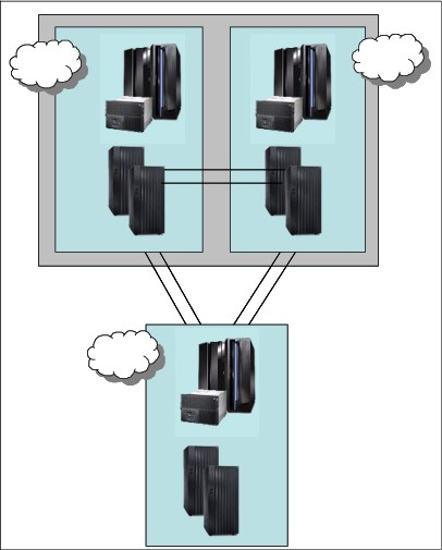
Figure 9-3 A 2-site solution: Campus and Recovery site
In the past, clients often used the bunker topology (as shown in Figure 9-4) to create a solution that could provide mirroring at extended distances, but still handle a primary site failure without data loss.
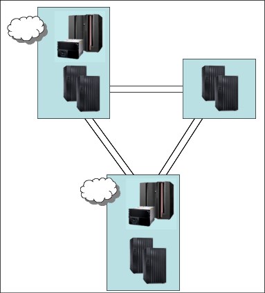
Figure 9-4 Two sites and an intermediate bunker
There are several arguments against this approach:
•For guaranteed zero data loss you need a policy in which, if the mirroring stops, the production applications are also stopped. There are clients who have implemented such a policy, but it is not a common policy. If production is allowed to continue after a local mirroring failure, then zero data loss cannot be guaranteed in all situations.
•If the disaster event also affects the bunker site or affects the bunker site first, then zero data loss is again not guaranteed. If the reason for the extended distance to the recovery site was to handle regional events, then this possibility cannot be excluded.
•The networking and hardware costs of the bunker site are probably still considerable despite there being no servers present. Further investment in the availability characteristics of the primary location or in a campus-type solution in which the synchronous secondary disk subsystems can be used for production services might provide a greater return on investment for the business.
9.2.2 Multi-target and cascading topologies
Multi-target and cascading topologies are similar in terms of capabilities in that both provide a synchronous and an asynchronous copy of the production data. Certain failure scenarios are handled more simply by multi-target solutions and other scenarios by cascading solutions.
The key requirements for either topology are as follows:
•A viable recovery copy and recovery capability is available at all times in a location other than where production is running. It is possible that regulatory requirements will demand this. This requirement implies that no situations exist in which both offsite copies are compromised.
•Any single site failure will result in only at most a short outage of the replication capability between the surviving sites to ensure minimal exposure where there might be increased data loss for a second failure.
With this requirement, being able to do incremental resynchronization between any two copies of the data is extremely desirable. Not having this can result in an extended period of exposure to additional data loss in case of a second failure.
9.2.3 Four-copy solutions
Many parallels can be drawn between 4-site solutions and the 3-site solutions presented in the previous section. That is, clients are unlikely to have four discrete physical data centers, because of cost implications. In all probability, the four-copy solution is most likely to be implemented in two physical locations where each location has two “hardened” data center facilities in the one location. For example, in two adjacent buildings on a campus, or even two separate data center halls within a single building where the halls are separated by fire resistant barriers and are independently provided with power and so on.
9.2.4 Cost considerations
The third and potentially fourth locations are, in many situations, regarded as an insurance copy and as mainly providing regulatory compliance. This might imply that costs for this location are kept to an absolute minimum.
Reducing the network bandwidth to remote locations can provide significant cost savings for the overall cost of the solution. Given that a synchronous copy is already available ‘locally’, trading off the RPO versus the cost of the network might be a useful compromise especially if the times of increased RPO are during periods of batch processing or database maintenance where the transactional data loss would be smaller.
Using a disaster recovery service provider such as IBM BCRS is one method of reducing the costs of the third location, fourth location, or both. Shared hardware assets and the removal of the requirement to invest in additional physical locations can provide significant cost benefits, and with the majority of events expected to be handled in the two main locations, the disadvantages of a shared facility are reduced.
9.2.5 Operational considerations
When running in multiple locations and combining different techniques together to provide an overall solution, there can be the requirement to do synchronized actions in both regions. To facilitate this from an operational standpoint, GDPS provides a Remote Script Execution function, so that from a single point of control you are able to initiate actions in any of the individual GDPS environments that make up the overall solution.
9.3 GDPS Metro Global - GM 3-site solution
This section describes the capabilities and requirements of the GDPS Metro Global - GM 3-site (GDPS MGM 3-site) solution. This solution combines the capabilities of GDPS Metro and GDPS GM. Synchronous replication between a primary and a secondary disk subsystem that are within a single data center, or between two data centers within metropolitan distances, is implemented with GDPS Metro in a single-leg configuration. GDPS GM is used to asynchronously replicate data to a third disk subsystem in a recovery site that is typically out of the local metropolitan region.
GDPS MGM is configured to use the MTMM technology to dynamically switch between a cascaded topology and a multi-target topology as necessary to optimize recovery scenarios such as HyperSwap. This configuration is referred to as a multi-target GDPS MGM 3-Site configuration.
9.3.1 GDPS MGM 3-site overview
The GDPS MGM 3-site configuration that is shown in Figure 9-5 is a 3-site continuous availability and DR solution. In this example, Site1 and Site2 are running an multi-site workload configuration (for more information, see 3.2.3, “Multisite workload configuration” on page 72) and are within metropolitan distances to ensure optimal application performance. All data that is required to recover critical workloads is on disk and is mirrored. Each site is configured with sufficient spare capacity to handle failed-over workloads during a site outage.
The third site, or recovery site, can be at virtually unlimited distance from Site1 and Site2 to protect against regional disasters. Asynchronous replication is running between Site2 and the recovery site. Redundant network connectivity is installed between Site1 and the recovery site to provide continued disaster recovery protection during a Site2 disaster or a failure of the disk subsystems in Site2. For more information, see “Incremental resynchronization for GDPS MGM 3-site” on page 276.
There is sufficient CPU capacity installed to support the R-sys. CBU is installed and GDPS will invoke CBU on IBM Z systems to provide the extra capacity that is needed to support production workloads if disaster recovery is started.

Figure 9-5 GDPS MGM 3-Site cascaded configuration
The RS1 disks in Region A, Site1are synchronously mirrored to the RS2 disks in Region A, Site2 by using Metro Mirror. The RS2 disks in Region A, Site2 are then asynchronously mirrored to a third set of disks, RS1, in the recovery region (Region B) by using Global Mirror.
A fourth set of disks (GMFC), also in the recovery region, are the FlashCopy targets that are used to provide the consistent data (“journal”) for disaster recovery. A fifth (FC1) and optional set of disks are used for stand-alone disaster recovery testing or, if a real disaster occurs, to create a “golden” or insurance copy of the data. For more information about Global Mirror, see Chapter 6, “GDPS Global - GM” on page 173.
Because some distance is likely to exist between the local sites, Site1 and Site2, running the Metro Mirror leg of MGM, and the remote recovery site that is the GM recovery site, we also distinguish between the local sites and the remote site using region terminology. Site1 and Site2 are in one region, Region A, and the remote recovery site is in another region, Region B.
Incremental resynchronization for GDPS MGM 3-site
The incremental resynchronization function of Metro Global Mirror enables incremental resynchronization between the surviving Region A replication site and the recovery site when the disk in the replication site in Region A that is hosting the GM session becomes unavailable.
Without this capability, if the disk in the replication site in Region A that is hosting the GM session becomes unavailable, the data at the recovery site begins to age because data can no longer be replicated between Region A and Region B. Instead of requiring a new Global Mirror session from the production site to the recovery site (and a full copy), the incremental resynchronization capability of GDPS MGM 3-site allows the recovery copy of data in Region B to be resynchronized from the surviving copy in Region A by only copying the changes that occurred since the error event took place.
Figure 9-6 shows how GDPS MGM 3-site can establish a Global Mirror session between the production site (RS1 in Region A), and the recovery site (RS1 in Region B) when it detects that the intermediate site (RS2 in Region A), which is hosting the GM session, becomes unavailable.
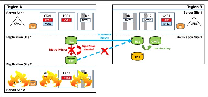
Figure 9-6 GDPS MGM 3-Site cascaded configuration after Site2 outage
After the Global Mirror session is established, only an incremental resynchronization of the changed data needs to be performed, which allows the disaster recovery capability to be restored in minutes, instead of hours.
Figure 9-7 shows a GDPS Metro Global - GM 3-site configuration when it is in a multi-target topology. GDPS Metro Global - GM 3-site configurations can dynamically switch between a cascaded topology and a multi-target topology to optimize processing of various recovery scenarios.
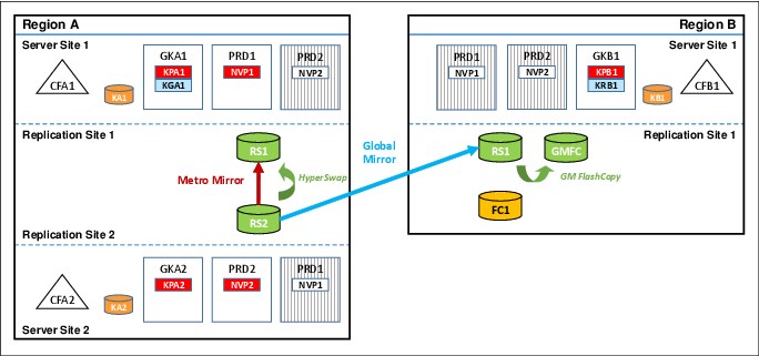
Figure 9-7 GDPS MGM 3-site multi-target configuration
Assume that your GDPS Metro Global - GM 3-Site configuration started out in a cascaded topology, as shown in Figure 9-5 on page 275. If you run a planned HyperSwap to the RS2 disk, followed by a reverse resynchronization of Metro Mirror from the RS2 disk back to the RS1 disk in Region A, the multi-target topology that is shown in Figure 9-7 results.
As shown in Figure 9-7, the RS2 disk is now the primary copy of data that application systems are currently accessing and the RS1 disk in Region A is the Metro Mirror secondary disk to the RS1 disk. HyperSwap was reenabled to provide high availability for the Region A data. This synchronous relationship is managed by GDPS Metro in Region A.
The RS2 disk also remains the Global Mirror primary disk that is copied to the RS1 disk in Region B (the Global Mirror secondary disk). This asynchronous relationship is managed by using GDPS GM. Incremental resynchronization is still enabled from the RS1 disk in Region A to the RS1 disk in Region B to protect from a failure of the RS2 disk and allow the Global Mirror copy to be re-established without the need for a full copy if the RS2 disk becomes unavailable.
The advantage of the multi-target capability in this scenario is that, following the HyperSwap, Global Mirror from the RS2 disk to the RS1 disk in Region B can remain active and maintain your DR position, while Metro Mirror in Region A is being resynchronized from the RS2 disk back to the RS1 disk.
GDPS MGM Procedure Handler
The GDPS MGM Procedure Handler is a fully integrated component of GDPS for use in 3-site IR or 4-site configurations. The Procedure Handler, along with the provided procedures, can be used to drive several complex scenarios with a single script invocation, as shown in the following examples:
•To incrementally reintroduce the RS2 intermediate disk if GM had been incrementally resynchronized from Site1 in Region A to the recovery site.
A supplied procedure provides the ability to return to a cascaded RS1-RS2-RS1 configuration when Global Mirror processing is moved to RS1 in Region A because of a loss of RS2. Without the procedure, returning to the cascaded configuration requires full initial copy for both Metro Mirror (RS1 disk to RS2 disk in Region A) and for GM (RS2 disk to RS1 disk in Region B). Therefore, the procedure provides significant availability and disaster recovery benefit for IR environments.
The procedure can be used for this purpose only if the RS2 disk is returned “intact,” meaning that metadata on the disk subsystem pertaining to its status as a Metro Mirror secondary and GM primary disk is still available. If you need to introduce a new disk subsystem into the configuration, this process requires full initial copy of all the data.
•To perform a planned toggle between the RS1 disk and the RS2 disk in Region A.
Another procedure allows you to perform periodic “flip/flops” of Site1 and Site2 (or RS1disk and RS2 disk) in Region A. This procedure HyperSwaps the host systems, resynchronizes Metro Mirror, and moves Global Mirror to the new Metro Mirror secondary for cascaded-only configurations.
•To incrementally “return home” after recovering production on the RS1 disk in Region B (or after you have performed a planned region switch to Region B) by reintroducing both the RS1 disk and the RS2 disk in Region A.
This capability is possible only if both sets of disk in Region A (RS1 and RS2) are returned intact. Although the MGM mirror can be incrementally reinstated, a production outage is necessary to move production from running in Region B back to running in Region A on either the RS1 or the RS2 disk.
The Procedure Handler supports only CKD disks. Incremental Resynchronization is not supported with GDPS Metro HyperSwap Manager.
9.3.2 GDPS MGM Site1 failures
The primary role of GDPS Metro is to protect the integrity of the RS2 copy of the data. At the first indication of a failure in Site1, GDPS Metro freezes all RS2 disks to prevent logical contamination of data that is on the RS2 devices. For more information about GDPS Metro processing, see Chapter 3, “GDPS Metro” on page 53.
At this point, the GDPS GM session between Site2 and the recovery site is still running, and both locations most likely will have the same set of data after a brief amount of time. The business focus is now on restarting the production systems in either Site2 or the recovery site, depending on the failure scenario. If the systems are started in Site2, the GDPS GM solution is already in place.
9.3.3 GDPS MGM Site2 failures
In this situation, the production systems are still running, so the business requirement is to ensure that disaster recovery capabilities are restored as fast as possible. The GDPS GM session should be restarted as soon as possible between Site1 and the recovery site by using incremental resynchronization. For more information, see “Incremental resynchronization for GDPS MGM 3-site” on page 276. If incremental resynchronization is not configured, a full copy is required.
This scenario has possibly less impact to the business than a failure of the production site, but this depends on the specific environment.
9.3.4 GDPS MGM region switch and return home
It is possible to switch production from running in Region A (in either Site1 or Site2) to Region B. Many GDPS MGM 3-site customers run Site1 and Site2 in the same physical site or on a campus where these two sites are separated by little distance. In such configurations, there might be planned outage events, such as complete power maintenance, that are likely to affect both sites.
Similarly, an unplanned event that impacts both sites will force recovery in Region B.
While production runs in Region B, the disk subsystems in this region track the updates that are made. When Region A is available again, assuming that all disks configured in the region come back intact, it is possible to return production back to Region A using the appropriate supplied procedure without requiring fully copying the data back. Because the updates have been tracked, only the data that changed while Region A was down are sent back to the Region A disks to bring them up to date. Then production is shut down in Region B. The final updates are allowed to be drained to Region A and production can then be restarted in Region A.
Because Region A and Region B are not symmetrically configured, the capabilities and levels of protection offered when production runs in Region B is different. Most notably, because there is only one copy of the production data in Region B, there is no HyperSwap protection to provide continuous data access. For the same reason, the various operational procedures for GDPS will also be different when running in Region B. However, even if no outage is planned for Region A, switching production to Region B periodically (for example, once or twice a year) and running live production there for a brief period of time is the best form of disaster testing because it will provide the best indication of whether Region B is properly configured to sustain real, live production workloads.
9.3.5 Scalability in a GDPS MGM 3-site environment
As described in “Addressing z/OS device limits in a GDPS Metro environment” on page 25, GDPS Metro allows defining the Metro Mirror secondary devices in alternate subchannel set 1 (MSS1), which allows up to nearly 64 K devices to be mirrored in a GDPS Metro configuration. The definitions of these devices are in the application site I/O definitions.
Similarly, “Addressing z/OS device limits in a GDPS GM environment” on page 34 describes how GM allows defining the GM FlashCopy target devices in alternative MSS1 (or not defining the GM FlashCopy target devices at all) in the recovery site I/O definitions. It also describes not defining the practice FlashCopy target devices at all to the GDPS GM R-sys, again, allowing up to nearly 64 K devices to be mirrored in a GDPS GM configuration.
In a GDPS MGM 3-site environment where the Metro Mirror secondary devices that are defined in MSS1 are the GM primary devices, there is additional support in GDPS GM that allows the GM primary devices to be defined in MSS1. With the combined alternate subchannel set support in GDPS Metro and GDPS GM, up to nearly 64 K devices can be replicated using the MGM technology.
9.3.6 Other considerations in a GDPS MGM 3-site environment
With Global Mirror, deliberately underconfiguring the bandwidth provided to reduce the total cost of the solution is possible. If significant peaks exist, then this cost savings might be considerable because the network costs are often a significant portion of ongoing costs. The drawback with under-configuring bandwidth can be that this could affect the recovery point that can be achieved. If a disaster affects the entire production region, both Site1 and Site2, during any peak when the GM mirror is running behind, there is likely to be more data loss.
9.3.7 Managing the GDPS MGM 3-site environment
GDPS provides a range of solutions for disaster recovery and continuous availability in a IBM Z-centric environment. GDPS MGM 3-site provides support for Metro Global Mirror within a GDPS environment. GDPS builds on facilities provided by System Automation and NetView and uses inband connectivity to manage the Metro Global Mirror relationships.
GDPS MGM 3-site runs two services to manage Metro Global Mirror, both of which run on z/OS systems. The GDPS Metro services run on every z/OS image in the production sysplex and the controlling systems, K1 and K2, in Site1 and Site2. Each controlling system is allocated on its own non-mirrored disk and has access to the primary and secondary disk subsystems.
During normal operations, the master function runs in the controlling system that is located where the secondary disks reside. This is where the day-to-day management and recovery of the Metro Mirror environment is performed. If Site1 or Site2 fails, the Master system manages the recovery of the Metro Mirror disks and production systems.
The second controlling system is an alternate that takes over the master function if the Master controlling system becomes unavailable or a Master switch takes place as result of, for example, a HyperSwap.
The GDPS GM services run in the Kg and R-sys controlling systems. Kg runs in the production sysplex and is responsible for controlling the Global Mirror environment and sending information to the R-sys running in the recovery site. The R-sys is responsible for carrying out all recovery actions during a wide-scale disruption that affect both Site1 and Site2.
In addition to managing the operational aspects of Global Mirror, GDPS GM provides facilities to restart IBM Z production systems in the recovery site. By providing scripting facilities, it provides a complete solution for the restart of an IBM Z environment in a disaster situation without requiring expert manual intervention to manage the recovery process.
9.3.8 GDPS MGM 3-site support for multiple IBM Z platforms
As described in 3.3.2, “Multiplatform Resiliency for IBM Z” on page 78, GDPS Metro provides near continuous availability for multiple IBM Z platforms (or operating systems), beyond z/OS, and their disk. Of these extra platforms, z/VM and its guests, including Linux on IBM Z systems, and IBM Db2 Analytics Accelerator on Z systems running in Secure Service Containers, are also supported by GDPS MGM in 3-site environments. That is, the disk for these systems can be mirrored to the recovery region by using Global Mirror and these systems can be brought up in the recovery region for planned and unplanned region switch scenarios and for disaster recovery testing.
9.3.9 Flexible testing in a GDPS MGM 3-site environment
To facilitate testing of site failover and failback processing, consider installing additional disk capacity to support FlashCopy in Site1 and Site2. The FlashCopy can be used at both Site1 and Site2 to maintain disaster recovery checkpoints during remote copy resynchronization. This ensures there is a consistent copy of the data available if a disaster-type event should occur while testing your site failover and failback procedures. In addition, the FlashCopy could be used to provide a copy to be used for testing or backing up data without the need for extended outages to production systems.
GDPS MGM 3-site supports another FlashCopy disk device, which is referred to as F disks or FC1 disks. These disks are other FlashCopy target devices that might be created in the recovery site. The F disks might be used to facilitate stand-alone testing of your disaster recovery procedures while the Global Mirror environment is running. This ensures that a consistent and current copy of the data is available at all times. In addition, the F disk can be used to create a “gold” or insurance copy of the data if a disaster situation occurs.
Currently, GDPS MGM 3-site supports the definition and management of a single F device for each Metro-Global Mirror triplet (RS1, RS2, RS1 disk combinations) in the configuration. To reduce management and operational complexity, support exists in GDPS GM to support the F disk without adding a requirement for these disks to be defined to the I/O configurations of the GDPS systems managing them. Known as “No UCB” FlashCopy, this support allows for the definition of F disks without the need to define additional UCBs to the GDPS management systems.
In addition to the ability to test on the F disks, GDPS MGM 3-site configurations support testing by using X-disk support in GDPS GM, as described in 6.6.2, “Creating a test copy using GM CGPause and testing on isolated disks” on page 199.
9.3.10 GDPS Query Services in a GDPS MGM 3-site environment
GDPS Metro provides Query Services, which allows you to query various aspects of the Metro Mirror leg of a GDPS MGM 3-site environment. Similarly, GDPS GM provides Query Services, which allows you to query various aspects of the GM leg of a GDPS MGM 3-site environment.
The GDPS GM query services also have awareness of the fact that a particular environment is a GDPS MGM 3-site environment enabled for Incremental Resynchronization (IR) and returns additional information pertaining to the IR aspects of the environment. In a GM environment, the GM session can be running from Site2 to the recovery site (RS2 to RS1) or from Site1 to the recovery site (RS1 to RS1) at any time.
If GM is currently running RS2 to RS1, this is the Active GM relationship and the RS1 to RS1 relationship is the Standby GM relationship. The GM query services in an MGM 3-site IR environment return information about both the active and the standby relationships for the physical and logical control units in the configuration and the devices in the configuration.
9.3.11 Easy Tier Heat Map Transfer in a GDPS MGM 3-site environment
As described in 3.7.5, “Easy Tier Heat Map Transfer” on page 107, GDPS Metro manages the transfer of Easy Tier learning within the Metro Mirror environment through a capability that is called Heat Map Transfer. Similarly, as described in 6.5.3, “Easy Tier Heat Map Transfer” on page 197, GDPS GM manages the transfer of Easy Tier learning within the Global Mirror environment.
In a GDPS MGM 3-site environment, the Heat Map Transfer functions of GDPS Metro and GDPS GM work together to manage the transfer of Easy Tier learning across the entire environment. When significant events occur, such as planned or unplanned HyperSwaps, planned or unplanned site switch or region switch events, or planned or unplanned removal or loss of the current Global Mirror primary disk set, the flow of data across the replication environment is affected. In these cases, GDPS automatically reconfigures the flow of Easy Tier learning information to match the new flow of data across the environment. This ability allows the ongoing Easy Tier learning process taking place in each disk subsystem in the environment to remain current and relevant so that performance effects that are related to subsequent events are minimized.
9.3.12 Prerequisites for GDPS MGM 3-site
GDPS MGM 3-site has the following prerequisites:
•GDPS Metro or GDPS HM. If GDPS HM is used, the Incremental Resynchronization function is not available.
•GDPS GM is required and the GDPS GM prerequisites must be met.
•Consult with your storage vendor to ensure that the required features and functions are supported on your disk subsystems.
|
Important: For the latest GDPS prerequisite information, see the GDPS product website.
|
9.3.13 GDPS MGM 3-site integration with GDPS Continuous Availability
Disk Replication Integration
It is possible to use cascaded-only GDPS MGM 3-Site to provide local high availability and remote disaster recover for the sysplexes that run GDPS Continuous Availability workloads. For such an environment, GDPS Continuous Availability provides special facilities to manage the disk replication aspects of specific planned and unplanned scenarios using the GDPS Continuous Availability Controller system as the single point of control. For more information, see , “In summary, GDPS Continuous Availability and GDPS Metro can be deployed in a complementary fashion. These products provide the necessary controls to facilitate any coordination that is required when operating on common resources.” on page 240 for details.
This support is not provided with GDPS MGM Multi-Target 3-Site.
Zero Data Loss at distance
GDPS MGM 3-Site can be integrated with GDPS Continuous Availability to provide a zero data loss (ZDL) capability for your most critical workloads, even when your data centers are separated by distances that exceed the capability of synchronous mirroring. For more information, see 7.6, “Zero Data Loss configuration” on page 240.
9.4 GDPS Metro Global - GM 4-site solution
The GDPS MGM 4-site solution is an extension of the GDPS MGM 3-Site solution, which is described in 9.3, “GDPS Metro Global - GM 3-site solution” on page 275. As such, the features and functions that are available with the 3-site solution also are available with the 4-site solution, with a few exceptions that are described later in this section.
The critical difference between the 3-site solution and the 4-site solution is that, with the 4-site solution, a second copy of data is available in the recovery region that can provide a high-availability (HA) copy if you perform a planned or unplanned switch of production to the recovery region. This means that the 4-site configuration is a symmetrical configuration because from a data high-availability perspective, the same capabilities are available whether you are running your production services in Region A or Region B.
This fourth copy of data is created using asynchronous Global Copy (also known as PPRC-XD) that can be switched to synchronous-mode (that is, Metro Mirror) during a planned or unplanned region switch, which provides the HA copy in that region.
Figure 9-8 shows an MGM 4-site configuration in a cascaded topology that consists of the four copies of data, labeled RS1 and RS2 in Region A and RS1 and RS2 in Region B. The Global Mirror FlashCopy target device (or “journal device”) is shown in Figure 9-8 as GMFC.
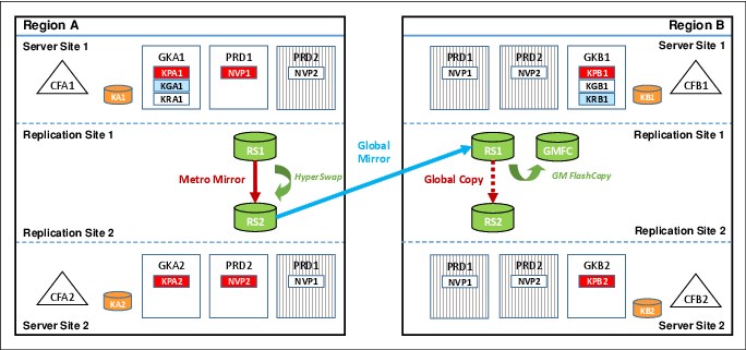
Figure 9-8 GDPS MGM 4-site cascaded configuration
In Figure 9-8, which shows a steady state when running in Region A, the RS1 disk in Region A is the primary copy of data that application systems are currently accessing. The RS2 disk in Region A is the Metro Mirror secondary disk to the RS1 disk, and HyperSwap is enabled to provide high availability for the Region A data. This relationship is managed by GDPS Metro running in Region A.
The RS2 disk in Region A is also the Global Mirror primary disk, being copied to the RS1 disk in Region B, which is the Global Mirror secondary disk. This is managed by using GDPS GM. Incremental resynchronization is also enabled from the RS1 disk in Region A to the RS1 disk in Region B to protect from a failure of the RS2 disk in Region A and allow the Global Mirror copy to be re-established without the need for a full copy. This is the same as a 3-site configuration. Where it differs is that the RS2 disk in Region B is present and is a Global Copy secondary to the RS1disk in Region B. This relationship, which is managed by GDPS Metro running in Region B, can be converted to fully synchronous Metro Mirror when you perform a switch of production to Region B for whatever reason.
If you switch production to Region B, you use the RS1 disk in Region B as the primary copy, with the RS2 disk in Region B being the Metro Mirror secondary, and the RS1 disk in Region A becomes the GM secondary. The RS2 disk in Region A are then the Global Copy secondary disk to the RS1 disk.
Figure 9-9 shows a GDPS MGM 4-site configuration when it is in a multi-target topology. GDPS MGM 4-site configurations can dynamically switch between a cascaded topology and a multi-target topology to optimize processing of various recovery scenarios.
Figure 9-9 GDPS MGM 4-site multi-target configuration
Assume that your GDPS MGM Multi-Site 4-Site configuration started out in a cascaded topology, as shown in Figure 9-8 on page 283. If you run a planned HyperSwap to the RS2 disk in Region A, followed by a resynchronization of Metro Mirror from the RS2 disk back to the RS1 disk, you find yourself in the multi-target topology that is shown in Figure 9-9. In the figure, the RS2 disk in Region A is now the primary copy of data that application systems are currently accessing and the RS1 disk is the Metro Mirror secondary disk.
HyperSwap was reenabled to provide high availability for the Region A data. This relationship is managed by GDPS Metro in Region A. The RS2 disk in Region A is also the Global Mirror primary disk, being copied to the RS1 disk in Region B, which is the Global Mirror secondary disk. This is managed by using GDPS GM. Incremental resynchronization is still enabled from the RS1 disk in Region A to the RS2 disk in Region B to protect from a failure of the RS2 disk in Region A and allow the Global Mirror copy to be re-established without the need for a full copy.
Finally, in Region B, the RS2 disk is still a Global Copy secondary to the RS1 disk. Again, this relationship, which is managed by GDPS Metro running in Region B, can be converted to fully synchronous Metro Mirror when you perform a switch of production to Region B for whatever reason.
The advantage of the multi-target capability in this scenario is that, following the HyperSwap, Global Mirror from the RS2 disk in Region A to the RS1 disk in Region B can remain active, which maintains your DR position, while Metro Mirror in Region A is being resynchronized from the RS2 disk back to the RS1 disk. In the same situation with cascaded-only MGM 4-Site, Global Mirror from the RS2 disk in Region A to the RS1 disk in Region B must be suspended while Metro Mirror in Region A is being resynchronized, which results in your DR position aging until the resync is complete.
The MGM 4-site configurations, as mentioned, remove the single point of failure of disk when you switch to the recovery region. As with GDPS MGM 3-site, precoded procedures are provided by GDPS to manage the following scenarios in the 4-site environments:
•Moving the GM session if there is a GM primary disk subsystem failure.
•Reintroduction of the intermediate disk subsystem.
•Planned Region switch to move production to the opposite region.
However, the following other considerations exist for an MGM 4-site configuration over those considerations for MGM 3-site configurations:
•More disk capacity does not need to be installed for X-disk or FC1 disk in each of the regions to facilitate testing of DR procedures while the Global Mirror environment is running. DR testing can be done on the RS2 disk in the current recovery region without affecting the DR position. For this reason, X-disk is not supported in GDPS MGM 3-site configurations.
However, a test copy can be created on an external disk subsystem other than RS2 in the recovery region, if required for reasons other than DR testing, such as seeding an external test environment with production data. This process can be done by using the Testcopy Manager feature. For more information, see 10.2, “Introduction to LCP and Testcopy Manager” on page 297.
•The use of asymmetric devices in the remote copy configuration is not supported.
•Use of GDPS HM is not supported in a 4-site configuration because the Incremental Resynchronization function is required.
•The integration points between GDPS MGM 3-site and GDPS Continuous Availability that is discussed in 9.3.13, “GDPS MGM 3-site integration with GDPS Continuous Availability” on page 282 are not available with GDPS MGM 4-site.
9.4.1 Benefits of a GDPS MGM 4-site configuration
You can probably see that in effect, a 4-site configuration is managed as two somewhat separate 3-site MGM configurations, where the fourth copy is most relevant when you perform a region switch, or when you want to perform a DR test. A 4-site MGM configuration includes the following key advantages:
•HA capability when running production in either region.
•Retention of DR capability following a region switch. In a 3-site MGM configuration, your DR position ages while running on the region B RS1 disk.
•Nearly identical operational procedures when running in either region.
One final advantage of the GDPS MGM 4-Site configuration is that the Test Copy Manager (TCM) feature is available. For more information about the benefits that are provided by this feature, see Chapter 10, “GDPS Logical Corruption Protection and Testcopy Manager” on page 295.
9.5 GDPS Metro Global - XRC 3-site
This section describes the capabilities and requirements of the GDPS Metro Global - XRC (GDPS MzGM) solution.
GDPS Metro Global - XRC is a multi-target data replication solution that combines the capabilities of GDPS Metro and GDPS XRC.
GDPS Metro or GDPS Metro HyperSwap Manager is used to manage the synchronous replication between a primary and secondary disk subsystem located either within a single data center, or between two data centers located within metropolitan distances.
GDPS XRC is used to asynchronously replicate data from the primary disks to a third disk system in a recovery site, typically out of the local metropolitan region. Because z/OS Global Mirror (XRC) supports only CKD devices, only IBM Z data can be mirrored to the recovery site.
For enterprises that want to protect IBM Z data, GDPS MzGM delivers a three-copy replication strategy to provide continuous availability for day-to-day disruptions, while protecting critical business data and functions during a wide-scale disruption.
9.5.1 GDPS MzGM overview
The solution that is shown in Figure 9-10 is an example of a 3-site GDPS MzGM continuous availability and DR implementation. In this example, Site1 and Site2 are running an Active/Active workload (see section 3.2.3, “Multisite workload configuration” on page 72) and located within metropolitan distances to ensure optimal application performance. All data that is required to recover critical workloads is resident on disk and mirrored. Each site is configured with sufficient spare capacity to handle failover workloads if there is a site outage.

Figure 9-10 GDPS MzGM
The third or recovery site can be located at a virtually unlimited distance from Site1 and Site2 locations to protect against regional disasters. Because of the extended distance, GDPS XRC is used to asynchronously replicate between Site1 and the recovery site.
Redundant network connectivity is installed between Site2 and the recovery site to provide continued data protection and DR capabilities during a Site1 disaster or a failure of the disk subsystems in Site1. For more information, see “Incremental resynchronization for GDPS MzGM” on page 287. Sufficient mainframe resources are allocated to support the SDMs and GDPS XRC controlling system. In a disaster situation, GDPS starts CBU to provide the extra capacity needed for production workloads.
The A disks are synchronously mirrored to the B disks in Site2 using Metro Mirror. In addition, A disks are asynchronously mirrored to a third (C) set of disks in the recovery site using z/OS Global Mirror (XRC). An optional, and highly recommended, fourth (F) set of disks in the recovery site is used to create FlashCopy of the C disks.
These disks can then be used for stand-alone disaster recovery testing, or in a real disaster, to create a “gold” or insurance copy of the data. For more information about z/OS Global Mirror, see Chapter 5, “GDPS Global - XRC” on page 149.
Because some distance is likely to exist between the local sites, Site1 and Site2, running the Metro Mirror leg of MzGM, and the remote recovery site, which is the XRC recovery site, we also distinguish between the local sites and the remote site using Region terminology. Site1 and Site2 are in one region, Region A and the remote recovery site is in another region, Region B.
Incremental resynchronization for GDPS MzGM
With the incremental resynchronization (IR) function of Metro z/OS Global Mirror, you should be able to move the z/OS Global Mirror (XRC) primary disk location from Site1 to Site2 or vice versa without having to perform a full initial copy of all data.
Without incremental resynchronization, if Site1 becomes unavailable and the Metro Mirror primary disk is swapped to Site2, the data at the recovery site starts to age because updates are no longer being replicated. The disaster recovery capability can be restored by establishing a new XRC session from Site2 to the recovery site. However, without incremental resynchronization, a full copy is required and this could take several hours or even days for significantly large configurations. The incremental resynch allows restoring the XRC mirror by using the Site2 disks as primary and sending to the recovery site only the changes that have occurred since the Metro Mirror disk switch.
Figure 9-11 shows how GDPS MzGM can establish a z/OS Global Mirror session between Site2 and the recovery site when it detects that Site1 is unavailable.
Figure 9-11 GDPS MzGM configuration after Site1 outage
After the session is established, only an incremental resynchronization of the changed data needs to be performed, thus allowing the disaster recovery capability to be restored in minutes, instead of hours, when the intermediate site is not available. GDPS can optionally perform this resynchronization of the XRC session using the swapped-to disks totally automatically, requiring no operator intervention.
9.5.2 GDPS MzGM Site1 failures
At the first indication of a failure, GDPS issues a freeze command to protect the integrity of the B copy of the disk. For more information about GDPS Metro processing, see Chapter 3, “GDPS Metro” on page 53.
If the freeze event were part of a larger problem in which you could no longer use the A-disk or Site1, you must recover the B-disk and restart production applications using the B-disk. After the production systems are restarted, the business focus will be on establishing z/OS Global (XRC) mirroring between Site2 and the recovery site as soon as possible. You can perform incremental resynchronization from the B-disk to the C-disk and maintain disaster recovery readiness.
If the failure was caused by a primary disk subsystem failure, and Site1 systems are not impacted, GDPS Metro uses HyperSwap to transparently switch all systems in the production sysplex to the secondary disks in Site2, and the production systems continue to run. In this case also, GDPS can perform incremental resynchronization from the B-disk to the C-disk and maintain disaster recovery readiness.
9.5.3 GDPS MzGM Site2 failures
In this situation, the production systems in Site1 will continue to run and replication to the remote site is still running. GDPS, based on user-defined actions, will restart Site2 production systems in Site1. No action is required from an application or disaster recovery solution perspective. This scenario has less impact to the business than a failure of the Site1 location. When Site2 is recovered, if the disks have survived, an incremental resynchronization can be initiated to resynchronize the A and B disks.
9.5.4 GDPS MzGM region switch and return home
It is possible to switch production from running in Region A (in Site1 or Site2) to Region B. Many GDPS MzGM customers run Site1 and Site2 in the same physical site or on a campus where these two sites are separated by little distance. In such configurations there could be planned outage events, such as complete power maintenance, that is likely to affect both sites.
Similarly, an unplanned event that impacts both sites will force recovery in Region B.
When Region A is available again, assuming that all disks configured in the region come back intact, it is possible to return production to Region A using a step-by-step procedure provided by GDPS to accomplish this return home operation.
To move data back to Region A, the z/OS Global Mirror (XRC) remote copy environment must be designed to allow the mirroring session to be reversed. Production will be running in Region B, and Region A will need to run the GDPS XRC SDM systems. This means you need to ensure that the proper connectivity and resources are configured in both regions to allow them to assume the recovery region role.
Because Region A and Region B are not symmetrically configured, the capabilities and levels of protection offered when production runs in Region B will be different. Most notably, because there is no Metro Mirror of the production data in Region B, there is no HyperSwap protection to provide continuous data access. For the same reason, the various operational procedures for GDPS will also be different when running in Region B.
However, even if no outage is planned for Region A, switching production to Region B periodically (for example, once or twice a year) and running live production there for a brief period of time is the best form of disaster testing because it will provide the best indication of whether Region B is properly configured to sustain real, live production workloads.
9.5.5 Scalability in a GDPS MzGM 3-site environment
As described in “Addressing z/OS device limits in a GDPS Metro environment” on page 25, GDPS Metro allows defining the Metro Mirror secondary devices in alternative subchannel set 1 (MSS1), which allows up to nearly 64 K devices to be mirrored in a GDPS Metro configuration. The definitions of these devices are in the application site I/O definitions.
Similarly, “Scalability in a GDPS XRC environment” on page 31 describes how GDPS XRC allows defining the FlashCopy target devices in MSS2 in the recovery site I/O definitions or not defining the FlashCopy target devices at all.
Also, in a GDPS MzGM 3-site environment where the Metro Mirror secondary devices that are defined in MSS1 are the XRC primary swap devices, more support is available in SDM and GDPS MzGM that allows these devices to be defined in MSS1 in the SDM systems. With the combined alternative subchannel set support in GDPS Metro and GDPS MzGM, nearly 32 K primary devices can be managed by each SDM system.
Finally, as described in “Multiple Extended Remote Copy” on page 30 and “Coupled Extended Remote Copy” on page 30, multiple clustered and coupled SDMs can be run across multiple z/OS images. This extra level of scalability allows the number of primary devices that can be protected by GDPS MzGM to reach the full, nearly 64 K device number limit.
9.5.6 Management of the GDPS MzGM 3-site environment
GDPS MzGM 3-site runs two services to manage Metro z/OS Global Mirror, both of which run on z/OS systems. The GDPS Metro management functions that are described in 9.3.7, “Managing the GDPS MGM 3-site environment” on page 280, are also provided by GDPS MzGM.
GDPS XRC services run on the Kx controlling system in the recovery site along with the SDM systems. The SDM and Kx systems must be in the same sysplex. The Kx controlling system is responsible for managing the z/OS Global Mirror (XRC) remote copy process and recovering the production systems if a disaster occurs. It does not detect what is happening in Site1 and Site2.
If a wide-scale disruption that impacts both Site1 and Site2 occurs, the operator must initiate the recovery action to restart production systems in the recovery site. At this point, the Kx system activates the production LPARs and coupling facilities, and is able to respond to certain z/OS initialization messages. However, it cannot automate the complete start of the production systems. For this, the K1 or K2 systems can be used to automate the application start and recovery process in the production sysplex.
9.5.7 Flexible testing of the GDPS MzGM 3-site environment
To facilitate testing of site failover and failback processing, consider installing additional disk capacity to support FlashCopy in Site1 and Site2. The FlashCopy can be used at both sites to maintain disaster recovery checkpoints during remote copy resynchronization. This ensures that a consistent copy of the data will be available if a disaster-type event should occur while testing your site failover and failback procedures.
In addition, the FlashCopy could be used to provide a copy to be used for testing or backing up data without the need for extended outages to production systems.
By combining z/OS Global Mirror with FlashCopy, you can create a consistent point-in-time tertiary copy of the z/OS Global Mirror (XRC) data sets and secondary disks at your recovery site. The tertiary devices can then be used to test your disaster recovery and restart procedures while the GDPS XRC sessions between Site1 and the recovery site are running, which ensures that disaster readiness is maintained at all times. In addition, these devices can be used for purposes other than DR testing; for example, nondisruptive data backup, data mining, or application testing.
With the addition of GDPS XRC Zero Suspend FlashCopy, enterprises are able to create the tertiary copy of the z/OS Global Mirror (XRC) data sets and secondary disks without having to suspend the z/OS Global Mirror (XRC) mirroring sessions. This GDPS function prevents the SDM from writing new consistency groups to the secondary disks while FlashCopy is used to create the tertiary copy of the disks.
The time to establish the FlashCopies will depend on the number of secondary SSIDs involved, the largest number of devices in any SSID, and the speed of the processor. Zero Suspend FlashCopy will normally be executed on the GDPS K-system in the recovery site, where there should be limited competition for CPU resources.
Because SDM processing is suspended while FlashCopy processing is occurring, performance problems in your production environment might occur if the SDM is suspended too long. For this reason, Zero Suspend FlashCopy should be evaluated by testing on your configuration, under different load conditions, to determine whether this facility can be used in your environment.
For enterprises that have requirements to test their recovery capabilities and maintain the currency of the replication environment, you will need to provide additional disk capacity to support FlashCopy. By providing an additional usable copy of the data, you have the flexibility to perform on-demand DR testing and other nondisruptive activities, while maintaining up-to-date DR readiness.
9.5.8 Easy Tier Heat Map Transfer in a GDPS MzGM 3-site environment
As described in 3.7.5, “Easy Tier Heat Map Transfer” on page 107, GDPS Metro manages the transfer of Easy Tier learning within the Metro Mirror environment through a capability that is called Heat Map Transfer. Similarly, as described in 5.5.5, “Easy Tier Heat Map Transfer” on page 167, GDPS XRC manages the transfer of Easy Tier learning within the XRC environment.
In a GDPS MzGM 3-site environment, the Heat Map Transfer functions of GDPS Metro and GDPS XRC work together to manage the transfer of Easy Tier learning across the entire environment. When significant events occur, such as planned or unplanned HyperSwaps or planned or unplanned site switch or region switch events, the flow of data across the replication environment is affected.
In these cases, GDPS automatically reconfigures the flow of Easy Tier learning information to match the new flow of data across the environment. This ability allows the ongoing Easy Tier learning process that is occurring in each disk subsystem in the environment to remain current and relevant so that performance effect that are related to subsequent events are minimized.
9.5.9 Prerequisites for GDPS MzGM
GDPS MzGM has the following prerequisites:
•GDPS Metro or GDPS HM is required.
•GDPS XRC is required and the GDPS XRC prerequisites must be satisfied.
•Consult with your storage vendor to ensure required features and functions are supported on your disk subsystems.
|
Important: For more information about the latest GDPS prerequisites, see this GDPS product website.
|
9.6 GDPS Metro Global - XRC 4-site solution
A GDPS MzGM 4-site configuration is an extension to the 3-site configuration as described in the previous section. As such, the features and functions available with the 3-site solution are also available with the 4-site solution, with a few exceptions mentioned later in this section.
The critical difference from the 3-site configuration is that in the recovery region, a second copy of data is available that can provide a high-availability (HA) copy if you perform either a planned or unplanned switch of production to the recovery region. This can also be described as a symmetrical 4-site configuration because the same capabilities, from a data high-availability perspective, are available whether you are running your production services in Region A or Region B.
This fourth copy of data is created using synchronous Metro Mirror and managed by GDPS Metro, thus providing the HA copy in that region.
Figure 9-12 shows a 4-site configuration consisting of the four copies of data, labeled A1, A2, B1, and B2.
Figure 9-12 GDPS MzGM 4-site configuration
In the figure, which shows a steady state when running in Region A, the A1 disk is the primary copy of data that application systems are currently accessing. The A2 disk is the Metro Mirror secondary disk to the A1 disk, and HyperSwap is enabled to provide high availability for the Region A data. This relationship is managed by GDPS Metro in Region A. The A1 disk is also the XRC primary disk, being copied to the B1 disk that is the XRC secondary disk. This is managed using GDPS XRC. Incremental resynchronization is also enabled from the A2 disk to the B1 disk to allow the XRC session to be re-established, without the need for a full copy, in the event of a planned or unplanned HyperSwap in Region A.
This is the same as a 3-site configuration. Where it differs is that the B2 disk is present and is a PPRC (aka Metro Mirror) secondary disk to the B1 disk. This relationship, which is managed by GDPS Metro running in Region B, is kept in a fully synchronous Metro Mirror state so that when you perform a switch of production to Region B for whatever reason, you are immediately protected by HyperSwap.
If you switch production to Region B, you then use the B1 disk as the primary copy, with the B2 disk now being the Metro Mirror secondary. The B1 disk is also the XRC primary disk with the A1 disk being the XRC secondary disk. The A2 disks are then the Metro Mirror secondary disk to the A1disk.
Several other considerations exist for an MzGM 4-site configuration over those previously mentioned for MzGM 3-site configurations:
•DR testing can be done on the B2 disk (when production is in Region A) without affecting your DR position (assuming the B2 disk is defined in MSS0).
•Use of GDPS HM is not supported in a 4-site configuration.
•xDR management for Native Linux on IBM Z is not supported in a 4-site configuration.
•Managing XRC on behalf of multiple GDPS Metro environments is not supported in a 4-site configuration.
9.6.1 Benefits of a GDPS MzGM 4-site configuration
You can probably see that, in effect, a 4-site configuration is managed as two somewhat separate 3-site MzGM configurations, where the fourth copy is most relevant when you perform a region switch, or when you want to perform a DR test. A 4-site MzGM configuration features the following the key advantages:
•HA capability when running production in either region
•Nearly identical operational procedures when running in either region
One final advantage of the GDPS MzGM 4-Site configuration is that the Logical Corruption Protection Manager (LCP) feature is available. For more information about the benefits that are provided by the LCP Manager feature, see Chapter 10, “GDPS Logical Corruption Protection and Testcopy Manager” on page 295.
1 Incremental Resynchronization of GDPS GM and management of four copy configurations are not supported in conjunction with GDPS Metro HyperSwap Manager.
..................Content has been hidden....................
You can't read the all page of ebook, please click here login for view all page.