

GDPS Metro
In this chapter we discuss the capabilities and prerequisites of the GDPS Metro offering. GDPS Metro supports both planned and unplanned situations, helping to maximize application availability and providing business continuity. A GDPS Metro solution delivers the following benefits:
•Near-continuous availability
•Disaster recovery (DR) across metropolitan distances
•Protection against multiple failures
GDPS Metro implemented in a dual leg configuration maintains three copies of your data so that even if one copy becomes unavailable, GDPS can continue to provide near-continuous availability and DR by using the remaining two copies.
•Recovery time objective (RTO) less than an hour
•Recovery point objective (RPO) of zero
The functions provided by GDPS Metro fall into two categories: Protecting your data and controlling the resources managed by GDPS. The following functions are among those that are included:
•Protecting your data:
– Ensuring the consistency of the secondary copies of your data in the event of a disaster or suspected disaster, including the option to also ensure zero data loss
– Transparent switching to either of the secondary disk sets using HyperSwap
•Controlling the resources managed by GDPS during normal operations, planned changes, and following a disaster:
– Monitoring and managing the state of the production z/OS systems and LPARs (shutdown, activating, deactivating, IPL, and automated recovery)
– Monitoring and managing z/VM guests (shutdown, activating, deactivating, IPL, and automated recovery)
– Managing the couple data sets and coupling facility recovery
– Support for switching your disk, or systems, or both, to another site
– User-customizable scripts that control how GDPS Metro reacts to specified error situations, which can also be used for planned events
This chapter includes the following topics:
3.1 Introduction to GDPS Metro
GDPS Metro is a continuous availability and disaster recovery solution that handles many types of planned and unplanned outages. As described in Chapter 1, “Introduction to business resilience and the role of GDPS” on page 1, most outages are planned, and even among unplanned outages, most are not disasters. GDPS Metro provides capabilities to address the required levels of availability across these outages and in a disaster scenario. These capabilities are described in this chapter.
3.1.1 Protecting data integrity and data availability with GDPS Metro
In 2.2, “Data consistency” on page 17, we point out that data integrity across primary and secondary volumes of data is essential to perform a database restart and accomplish an RTO of less than hour. This section includes details about how GDPS Metro automation provides both data consistency if there are mirroring problems and data availability if there are primary disk problems.
The following types of disk problems trigger a GDPS automated reaction:
•Mirroring problems (Freeze triggers). No problem exists writing to the primary disk subsystem, but a problem exists mirroring the data to one or both of the secondary disk subsystems. For more information, see “GDPS Freeze function for mirroring failures” on page 55.”
•Primary disk problems (HyperSwap triggers). There is a problem writing to the primary disk: either a hard failure, or the disk subsystem is not accessible.
GDPS Freeze function for mirroring failures
GDPS uses automation, keyed off events or messages, to stop all mirroring for a given replication leg when a remote copy failure occurs between one or more of the primary/secondary disk subsystem pairs on that replication leg. In particular, the GDPS automation uses the IBM PPRC Freeze and Run architecture, which has been implemented as part of Metro Mirror on IBM disk subsystems and also by other enterprise disk vendors. In this way, if the disk hardware supports the Freeze and Run architecture, GDPS can ensure consistency across all data in the sysplex (consistency group), regardless of disk hardware type.
This preferred approach differs from proprietary hardware approaches that work only for one type of disk hardware. For more information about data consistency with synchronous disk mirroring, see “Metro Mirror data consistency” on page 24.
When a mirroring failure occurs, this problem is classified as a Freeze trigger and GDPS stops activity across all disk subsystems for the affected replication leg at the time the initial failure is detected, thus ensuring that the dependent write consistency of the secondary disks for that replication leg is maintained. Note that in a dual-leg environment, mirroring activity for the other replication leg is not affected by the freeze.
The following process occurs when a GDPS performs a Freeze:
1. Remote copy is suspended for all device pairs on the affected replication leg.
2. While the suspend command is being processed for each LSS, each device goes into a long busy state. When the suspend completes for each device, z/OS marks the device unit control block (UCB) in all connected operating systems to indicate an Extended Long Busy (ELB) state.
3. No I/Os can be issued to the affected devices until the ELB is thawed with the PPRC Run (or “thaw”) action or until it times out. (The consistency group timer setting commonly defaults to 120 seconds, although for most configurations a longer ELB is preferable.)
4. All paths between the Metro Mirrored disks on the affected replication leg are removed, which prevents further I/O to the associated secondary disks if Metro Mirror is accidentally restarted.
Because no I/Os are processed for a remote-copied volume during the ELB, dependent write logic ensures the consistency of the affected secondary disks. GDPS performs a Freeze for all LSS pairs that contain GDPS managed mirrored devices.
|
Important: Because of the dependent write logic, it is not necessary for all LSSs to be frozen at the same instant. In a large configuration with many thousands of remote copy pairs, it is not unusual to see short gaps between the times when the Freeze command is issued to each disk subsystem. Because of the ELB, however, such gaps are not a problem.
|
After GDPS performs the Freeze and the consistency of the secondary disks on the affected leg is protected, the action GDPS takes next depends on the client’s PPRCFAILURE policy (also known as Freeze policy). For more information about the actions GDPS takes based on this policy, see “Freeze policy (PPRCFAILURE policy) options” on page 57.
GDPS Metro uses a combination of storage subsystem and sysplex triggers to automatically secure, at the first indication of a potential disaster, a data-consistent secondary copy of your data using the Freeze function. In this way, the secondary copy of the data is preserved in a consistent state, perhaps even before production applications are aware of any issues.
Ensuring the data consistency of the secondary copy ensures that a normal system restart can be performed instead of having to perform DBMS forward recovery actions. This is an essential design element of GDPS to minimize the time to recover the critical workloads in the event of a disaster in the primary site.
You can appreciate why such a process must be automated. When a device suspends, there is not enough time to launch a manual investigation process. The entire mirror for the affected leg must be frozen by stopping further I/O to it, and then the policy indicates whether production will continue to run with mirroring temporarily suspended, or whether all systems should be stopped to guarantee zero data loss.
In summary, a freeze is triggered as a result of a Metro Mirror suspension event for any primary disk in the GDPS configuration; that is, at the first sign that a duplex mirror that is going out of the duplex state. When a device suspends, all attached systems are sent a “State Change Interrupt” (SCI). A message is issued in all of those systems and then each system must issue multiple I/Os to investigate the reason for the suspension event.
When GDPS performs a freeze, all primary devices in the Metro Mirror configuration suspend for the affected replication leg. This can result in significant SCI traffic and many messages in all of the systems. GDPS, with z/OS and microcode on the DS8000 disk subsystems, supports reporting suspensions in a summary message per LSS instead of at the individual device level. This feature is known as Summary Event Notification for PPRC Suspends (PPRCSUM). When compared to reporting suspensions on a per devices basis, PPRCSUM dramatically reduces the message traffic and extraneous processing associated with Metro Mirror suspension events and freeze processing.
Freeze policy (PPRCFAILURE policy) options
As we have described, when a mirroring failure is detected on a replication leg, GDPS automatically and unconditionally performs a Freeze of that leg to secure a consistent set of secondary volumes in case the mirroring failure could be the first indication of a site failure. Because the primary disks are in the Extended Long Busy state as a result of the freeze and the production systems are locked out, GDPS must take some action. Here, there is no time to interact with the operator on an event-by-event basis. The action must be taken immediately. The action to be taken is determined by a customer policy setting, that is, the PPRCFAILURE policy option (also known as the Freeze policy option). GDPS will use this same policy setting after every Freeze event to determine what its next action should be. The policy can be specified at a leg level allowing a different policy specification for each of the replication legs. The following options are available:
•PPRCFAILURE=GO (Freeze and Go)
GDPS allows production systems to continue operation after mirroring is suspended.
•PPRCFAILURE=STOP (Freeze and Stop)
GDPS resets production systems while I/O is suspended.
•PPRCFAILURE=STOPLAST
This option is only relevant to dual-leg configurations. When it is specified, GDPS checks the mirroring status of the other replication leg. If the status of the other leg is OK, GDPS performs a Go. If not, and this is the last viable leg that GDPS has just frozen, GDPS performs a Stop.
•PPRCFAILURE=COND (Freeze and Stop conditionally)
GDPS tries to determine if a secondary disk caused the mirroring failure. If so, GDPS performs a Go. If not, GDPS performs a Stop.
•PPRCFAILURE=CONDLAST
This option is only relevant to dual-leg configurations. When it is specified, GDPS checks the mirroring status of the other replication leg. If the status of the other leg is OK, GDPS performs a Go. If not (the freeze was performed on the last viable leg), GDPS tries to determine if a secondary disk caused the mirroring failure. If so, GDPS performs a Go. If not, GDPS performs a Stop.
Freeze and Go
With this policy, after performing the Freeze, GDPS performs a Run action against all primary LSSs, which is also known as performing a Go. Performing a Go removes the ELB and allows production systems to continue using these devices. The devices will be in remote copy-suspended mode in relation to the secondary devices on the affected leg, so any further writes to these devices are no longer being mirrored to the secondary devices on that leg (writes will continue to be mirrored to the secondary devices on the other leg in dual-leg configurations, assuming that mirroring on that leg is in duplex status at the time). However, changes are being tracked by the hardware so that, later, only the changed data will be resynchronized to the secondary disks and the affected leg.
With this policy you avoid an unnecessary outage for a false freeze event, that is, if the trigger is simply a transient event. However, if the trigger turns out to be the first sign of an actual disaster, you might continue operating for an amount of time before all systems fail. Any updates made to the primary volumes during this time are not replicated to the secondary disk on the affected leg, and therefore are lost if you end up having to recover on those secondary disk. In addition, because the CF structures were updated after the secondary disks were frozen, the CF structure content is not consistent with the secondary disks. Therefore, the CF structures in either site cannot be used to restart workloads and log-based restart must be used when restarting applications.
This is not full forward recovery. It is forward recovery of any data, such as DB2 group buffer pools, that might have existed in a CF but might not have been written to disk yet. This results in prolonged recovery times. The duration depends on how much such data existed in the CFs at that time. With a Freeze and Go policy, you might consider tuning applications such as DB2, which can harden such data on disk more frequently than otherwise.
Freeze and Go is a high availability option that avoids production outage for false freeze events. However, it carries a potential for data loss.
Freeze and Stop
With this policy, you can be assured that no updates are made to the primary volumes after the Freeze because all systems that can update the primary volumes are reset. This ensures that no more updates can occur to the primary disks because such updates would not be mirrored to the affected secondary disk, meaning that it would not be possible to achieve zero data loss if a failure occurs (or if the original trigger was an indication of a catastrophic failure) and recovery on the affected secondary disk is required.
You can choose to restart the systems when you want. For example, if this was a false freeze (that is, a false alarm), then you can quickly resynchronize the mirror and restart the systems only after the mirror is duplex.
If you are using duplexed coupling facility (CF) structures along with a Freeze and Stop policy, it might seem that you are guaranteed to use the duplexed instance of your structures if you must recover and restart your workload with the frozen secondary copy of your disks. However, this is not always the case. There can be rolling disaster scenarios where before, after, or during the freeze event, there is an interruption (perhaps failure of CF duplexing links) that forces CFRM to drop out of duplexing.
There is no guarantee that it is the structure instance in the surviving site that is kept. It is possible that CFRM keeps the instance in the site that is about to totally fail. In this case, there will not be an instance of the structure in the site that survives the failure.
To summarize, with a Freeze and Stop policy, if there is a surviving, accessible instance of application-related CF structures, this instance will be consistent with the frozen secondary disks. However, depending on the circumstances of the failure, even with structures duplexed across two sites you are not 100% guaranteed to have a surviving, accessible instance of the application structures and therefore you must have the procedures in place to restart your workloads without the structures.
Although a Stop policy can be used to ensure no data loss, if a failure occurs that is a false freeze event, that is, it is a transient failure that did not necessitate recovering using the frozen disks, it results in unnecessarily stopping the systems.
Freeze and Stop last
For dual-leg configurations, when this policy option is specified, after the Freeze, GDPS checks the status of mirroring on the other replication leg (the leg other than the one that was just frozen) to determine whether the leg that just frozen was the last leg actively replicating data. If the other leg is still actively replicating data, GDPS performs a Go. But if the other leg is already frozen or mirroring status is not OK, GDPS performs a Stop.
When you have only one replication leg defined in your configuration (you have only one secondary copy of your data), using this policy specification is the same as using a Freeze and Stop policy.
Freeze and Stop conditional
Field experience has shown that most of the Freeze triggers are not necessarily the start of a rolling disaster, but are “False Freeze” events that do not necessitate recovery on the secondary disk. Examples of such events include connectivity problems to the secondary disks and secondary disk subsystem failure conditions.
With a COND policy, the action that GDPS takes after it performs the Freeze is conditional. GDPS tries to determine if the mirroring problem was as a result of a permanent or temporary secondary disk subsystem problem:
•If GDPS can determine that the freeze was triggered as a result of a secondary disk subsystem problem, GDPS performs a Go. That is, it allows production systems to continue to run by using the primary disks. However, updates will not be mirrored until the secondary disk can be fixed and Metro Mirror can be resynchronized.
•If GDPS cannot ascertain that the cause of the freeze was a secondary disk subsystem, GDPS operates on the assumption that this could still be the beginning of a rolling disaster in the primary site and performs a Stop, resetting all the production systems to guarantee zero data loss. GDPS cannot always detect that a particular freeze trigger was caused by a secondary disk, and that some freeze events that are in fact caused by a secondary disk could still result in a Stop.
For GDPS to determine whether a freeze trigger might have been caused by the secondary disk subsystem, the IBM DS8000 disk subsystems provide a special query capability known as the Query Storage Controller Status microcode function. If all disk subsystems in the GDPS managed configuration support this feature, GDPS uses this special function to query the secondary disk subsystems in the configuration to understand the state of the secondaries and if one of these secondaries might have caused the freeze. If you use the COND policy setting but all disks in your configuration do not support this function, GDPS cannot query the secondary disk subsystems, and the resulting action is a Stop.
This option can provide a good compromise where you can minimize the chance that systems would be stopped for a false freeze event and increase the chance of achieving zero data loss for a real disaster event.
Freeze and Stop conditional last
For dual-leg configurations, when this policy option is specified, after the Freeze, GDPS checks the status of mirroring on the other replication leg (the leg other than the one that was just frozen) to determine if the leg just frozen was the last leg actively replicating data. If the other leg is still actively replicating data, GDPS performs a Go. If the other leg is already frozen or mirroring status is not OK, GDPS performs conditional Stop processing; that is, it queries the secondary disk subsystem and performs a Go if, as a result of the query, it determines that the freeze was caused by the secondary, but performs a Stop if it cannot determine for sure that the problem was caused by the secondary.
When you only have one replication leg defined in your configuration (you only have one secondary copy of your data), using this policy specification is the same as using a Freeze and Stop conditional policy.
PPRCFAILURE policy selection considerations
The PPRCFAILURE policy option specification directly relates to recovery time and recovery point objectives (RTO and RPO, respectively), which are business objectives.Therefore, the policy option selection is really a business decision rather than an IT decision. If data associated with your transactions is high-value, it might be more important to ensure that no data associated with your transactions is ever lost, so you might decide on a Freeze and Stop policy.
If you have huge volumes of relatively low-value transactions, you might be willing to risk some lost data in return for avoiding unnecessary outages with a Freeze and Go policy. The Freeze and Stop Conditional policy attempts to minimize the chance of unnecessary outages and the chance of data loss; however, there is still a risk of either, however small.
The various PPRCFAILURE policy options, combined with the fact that the policy options are specified on a per replication leg basis (different policies can be specified for different legs), gives you the flexibility to refine your policies to meet your unique business goals.
For example, if your RPO is zero, you can use the following PPRCFAILURE policy:
•For RL2, Freeze and Stop (PPRCFAILURE=STOP)
Because RS3 is your disaster recovery copy and you must ensure that you never lose data should you ever have to recover and run on the RS3 disk, you must always unconditionally stop the systems to ensure that no further updates occur to the primary disks that could be lost in a recovery scenario.
•For RL1, Freeze and Stop on last leg only (STOPLAST)
You do not need to take a production outage when Metro Mirror freezes on the high-availability leg if RL2 is still functional and continues to provide disaster recovery protection. However, if RL2 is not functional when Metro Mirror on RL1 suspends, you might want to at least retain the capability to recover on RS2 disk with zero data loss if it becomes necessary.
However, if you want to avoid unnecessary outages at the risk of losing data if there is an actual disaster, you can specify Freeze and Go for both of your replication legs.
GDPS HyperSwap function
If there is a problem writing or accessing the primary disk because of a failing, failed, or inaccessible or non-responsive disk, there is a need to swap from the primary disks to one of the sets of secondary disks.
GDPS Metro delivers a powerful function known as HyperSwap. HyperSwap provides the ability to swap from using the primary devices in a mirrored configuration to using what had been one of the sets of secondary devices, in a manner that is transparent to the production systems and applications using these devices. Before the availability of HyperSwap, a transparent disk swap was not possible. All systems using the primary disk would have been shut down (or might have failed, depending on the nature and scope of the failure) and would have been re-IPLed using the secondary disks. Disk failures were often a single point of failure for the entire sysplex.
With HyperSwap, such a switch can be accomplished without IPL and with just a brief hold on application I/O. The HyperSwap function is completely controlled by automation, thus allowing all aspects of the disk configuration switch to be controlled through GDPS.
HyperSwap can be invoked in two ways:
•Planned HyperSwap
A planned HyperSwap is invoked by operator action using GDPS facilities. One example of a planned HyperSwap is where a HyperSwap is initiated in advance of planned disruptive maintenance to a disk subsystem.
•Unplanned HyperSwap
An unplanned HyperSwap is invoked automatically by GDPS, triggered by events that indicate the primary disk problem.
Primary disk problems can be detected as a direct result of an I/O operation to a specific device that fails because of a reason that indicates a primary disk problem such as:
– No paths available to the device
– Permanent error
– I/O timeout
In addition to a disk problem being detected as a result of an I/O operation, it is also possible for a primary disk subsystem to proactively report that it is experiencing an acute problem. The IBM DS8000 provides a special microcode function known as the Storage Controller Health Message Alert capability. Problems of different severity are reported by disk subsystems that support this capability. Those problems classified as acute are also treated as HyperSwap triggers. After systems are swapped to use the secondary disks, the disk subsystem and operating system can try to perform recovery actions on the former primary without impacting applications since the applications are no longer using those disks.
Planned and unplanned HyperSwap have requirements in terms of the physical configuration, such as having to be symmetrically configured, and so on. While a client’s environment meets these requirements, there is no special enablement required to perform planned swaps. Unplanned swaps are not enabled by default and must be enabled explicitly as a policy option. This is described in more detail in “Preferred Swap Leg and HyperSwap (Primary Failure) policy options” on page 62.
When a swap is initiated, GDPS always validates various conditions to ensure that it is safe to swap. For example, if the mirror is not fully duplex on a given leg, that is, not all volume pairs are in a duplex state, a swap cannot be performed on that leg. The way that GDPS reacts to such conditions changes depending on the condition detected and whether the swap is a planned or unplanned swap.
Assuming that there are no show-stoppers and the swap proceeds, for both planned and unplanned HyperSwap, the systems that are using the primary volumes will experience a temporary pause in I/O processing. GDPS blocks I/O both at the channel subsystem level by performing a Freeze which results in all disks going into Extended Long Busy, and also in all systems, where I/O is quiesced at the operating system (UCB) level. This is to ensure that no systems use the disks until the switch is complete. During the time when I/O is paused, the following process is completed:
1. The Metro Mirror configuration is physically switched. This includes physically changing the secondary disk status to primary. Secondary disks are protected and cannot be used by applications. Changing their status to primary allows them to come online to systems and be used.
2. The disks will be logically switched in each of the systems in the GDPS configuration. This involves switching the internal pointers in the operating system control blocks (UCBs). After the switch, the operating system will point to the former secondary devices which will be the new primary devices.
3. Finally, the systems resume operation using the new, swapped-to primary devices. The applications are not aware of the fact that different devices are now being used.
This brief pause during which systems are locked out of performing I/O is known as the User Impact Time. In benchmark measurements at IBM using currently supported releases of GDPS and IBM DS8000 disk subsystems, the User Impact Time to swap 10,000 pairs across 16 systems during an unplanned HyperSwap was less than 10 seconds. Most implementations are actually much smaller than this and typical impact times in a well-configured environment using the most current storage and server hardware are measured in seconds. Although results will depend on your configuration, these numbers give you a high-level idea of what to expect.
HyperSwap can be executed on either replication leg in a GDPS Metro dual-leg environment. For a planned swap, you must specify which leg you want to use for the swap. For an unplanned swap, which leg is chosen depends on many factors, including your HyperSwap policy. This is described in more detail in “Preferred Swap Leg and HyperSwap (Primary Failure) policy options” on page 62.
After a replication leg is selected for the HyperSwap, GDPS swaps all devices on the selected replication leg. Just as the Freeze function applies to the entire consistency group, HyperSwap is for the entire consistency group. For example, if a single mirrored volume fails and HyperSwap is invoked, processing is swapped to one of the sets of secondary devices for all primary volumes in the configuration, including those in other, unaffected, disk subsystems. This is to ensure that all primary volumes remain in the same site. If HyperSwap were to swap only the failed LSS, you would then have several primaries in one location, and the remainder in another location. This would make for a significantly complex environment to operate and administer I/O configurations.
Incremental Resynchronization
For dual-leg configurations, when a disk switch or recovery on one of the secondaries occurs, MTMM provides for a capability known as “incremental resynchronization” (IR). Assume your RS1 disks are the current primaries and the RS2 and RS3 disks are the current secondaries. If you switch from using RS1 to using RS2 as your primary disks, to maintain a multi-target configuration, you will need to establish replication on RL1, between RS2 and RS1, and on RL3, between RS2 and RS3. A feature of the Metro Mirror copy technology known as Failover/Failback, together with the MTMM IR capability allows you to establish replication for RL1 and RL3 without having to copy all of the data from RS2 to RS1 or from RS2 to RS3. Only the changes that occur on B after the switch to B are copied in order to resynchronize the two legs.
If there is an unplanned HyperSwap from RS1 to RS2, because RS1 has failed, replication can be established on RL3 between RS2 and RS3 in order to restore disaster recovery readiness. Again, this is an incremental resynchronization (only changed tracks are copied), so the duration to get to a protected position will be much faster compared to performing an initial copy for the leg.
HyperSwap with less than full channel bandwidth
You may consider enabling unplanned HyperSwap on the cross-site replication leg (RL2), even if you do not have sufficient cross-site channel bandwidth to sustain the full production workload for normal operations. Assuming that a disk failure is likely to cause an outage and that you have to switch to using the RS3 disk in the other site (because the RS2 disks in the same site are down at the time), the unplanned HyperSwap to RS3 might at least present you with the opportunity to perform an orderly shutdown of your systems first. Shutting down your systems cleanly avoids the complications and restart time elongation associated with a crash-restart of application subsystems.
Preferred Swap Leg and HyperSwap (Primary Failure) policy options
Clients might prefer not to immediately enable their environment for unplanned HyperSwap when they first implement GDPS. For this reason, unplanned HyperSwap is not enabled by default. However, we strongly suggest that all GDPS Metro clients enable their environment for unplanned HyperSwap, at a minimum, on the local replication leg (RL1) if it is configured. Both copies of disk on the RL1 leg (RS1 and RS2) are local and therefore distance and connectivity should not be an issue.
You control the actions that GDPS takes for primary disk problems by specifying a Primary Failure policy option. This option is applicable to both replication legs. However, you have the option of overriding this specification at a leg level and request a different action based on which leg is selected by GDPS to act upon. Furthermore, there is the Preferred Swap Leg policy, which is factored in when GDPS decides which leg to act upon as a result of a primary disk problem trigger.
Preferred Swap Leg selection for unplanned HyperSwap
In a dual-leg configuration, a primary disk problem trigger is common to both replication legs because the primary disk is common to both legs. Before acting on the trigger, GDPS first needs to select which leg to act upon. GDPS provides you with the ability to influence this decision by specifying a Preferred Swap Leg policy. GDPS will attempt to select the leg that you have identified as the Preferred Swap Leg first. However, if this leg is not eligible for the action that you specified in your Primary Failure policy, GDPS attempts to select the other active replication leg. These are among the reasons that your Preferred Swap Leg might not be eligible for selection:
•It is currently the MTIR leg.
•All pairs for the leg are not in a duplex state.
•It is currently not HyperSwap enabled.
HyperSwap retry on non-preferred leg
If the preferred leg is viable and selected for an unplanned swap, there is still a possibility (albeit small) that the swap on this leg fails for some reason. When swap on the first leg fails, if the other replication leg is enabled for HyperSwap, GDPS will retry the swap on the other leg. This maximizes the chances of a successful swap.
Primary failure policy options
After GDPS has selected which leg it will act on when a primary disk problem trigger occurs, the first thing it will do will be a Freeze on the selected leg (the same as is performed when a mirroring problem trigger is encountered). GDPS then applies the Primary Failure policy option specified for that leg. The Primary Failure policy for each leg can specify a different action. You can specify the following Primary Failure policy options:
•PRIMARYFAILURE=GO
No swap is performed. The action GDPS takes is the same as for a freeze event with policy option PPRCFAILURE=GO. A Run action is performed, which will allow systems to continue using the original primary disks. Metro Mirror is suspended and therefore updates are not being replicated to the secondary. Note, however, that depending on the scope of the primary disk problem, it might be that some or all production workloads simply cannot run or cannot sustain required service levels. Such a situation might necessitate restarting the systems on the secondary disks. Because of the freeze, the secondary disks are in a consistent state and can be used for restart. However, any transactions that ran after the Go action will be lost.
•PRIMARYFAILURE=STOP
No swap is performed. The action GDPS takes is the same as for a freeze event with policy option PPRCFAILURE=STOP. GDPS system-resets all the production systems. This ensures that no further I/O occurs. After performing situation analysis, if it is determined that this was not a transient issue and that the secondaries should be used to IPL the systems again, no data will be lost.
•PRIMARYFAILURE=SWAP,swap_disabled_action
The first parameter, SWAP, indicates that after performing the Freeze, GDPS will proceed with performing an unplanned HyperSwap. When the swap is complete, the systems will be running on the new, swapped-to primary disks (former secondaries). Mirroring on the selected leg will be in a suspended state; because the primary disks are known to be in a problematic state, there is no attempt to reverse mirroring. After the problem with the primary disks is fixed, you can instruct GDPS to resynchronize Metro Mirror from the current primaries to the former ones (which are now considered to be secondaries).
The second part of this policy, swap_disabled_action, indicates what GDPS should do if HyperSwap had been temporarily disabled by operator action at the time the trigger was encountered. Effectively, an operator action has instructed GDPS not to perform a HyperSwap, even if there is a swap trigger. GDPS has already performed a freeze. The second part of the policy control what action GDPS will take next.
The following options (which are in effect only if HyperSwap is disabled by the operator) are available for the second parameter (remember that the disk is already frozen):
GO This is the same action as GDPS would have performed if the policy option had been specified as PRIMARYFAILURE=GO.
STOP This is the same action as GDPS would have performed if the policy option had been specified as PRIMARYFAILURE=STOP.
Preferred Swap Leg and Primary Failure policy selection considerations
For the Preferred Swap Leg policy, consider whether you can tolerate running with disk and systems in opposite sites with no/minimal performance impact. If that is acceptable, you can choose either leg, although it might be better to prefer the RL2 (Site1-Site2) leg. If you cannot tolerate running with disks and systems in opposite sites, choose the RL1, local leg.
For the Primary Failure policy, again we recommend that you specify SWAP for the first part of the policy option to enable HyperSwap, at least on the local replication leg (RL1). If distance and connectivity between your sites is not an issue, consider specifying SWAP for the first part of the policy on the remote replication leg (RL2) also.
For the Stop or Go choice, either as the second part of the policy option or if you will not be using SWAP, similar considerations apply as for the PPRCFAILURE policy options to Stop or Go. Go carries the risk of data loss if it is necessary to abandon the primary disk and restart systems on the secondary. Stop carries the risk of taking an unnecessary outage if the problem was transient. The key difference is that with a mirroring failure, the primary disks are not broken. When you allow the systems to continue to run on the primary disk with the Go option, other than a disaster (which is low probability), the systems are likely to run with no problems. With a primary disk problem, with the Go option, you are allowing the systems to continue running on what are known to be disks that experienced a problem just seconds ago. If this was a serious problem with widespread impact, such as an entire disk subsystem failure, the applications will experience severe problems. Some transactions might continue to commit data to those disks that are not broken. Other transactions might be failing or experiencing serious service time issues. Also, if there is a decision to restart systems on the secondary because the primary disks are simply not able to support the workloads, there will be data loss. The probability that a primary disk problem is a real problem that will necessitate restart on the secondary disks is much higher when compared to a mirroring problem. A Go specification in the Primary Failure policy increases your risk of data loss.
If the primary failure was of a transient nature, a Stop specification results in an unnecessary outage. However, with primary disk problems, the probability that the problem could necessitate restart on the secondary disks is high, so a Stop specification in the Primary Failure policy avoids data loss and facilitates faster restart.
The considerations relating to CF structures with a PRIMARYFAILURE event are similar to a PPRCFAILURE event. If there is an actual swap, the systems continue to run and continue to use the same structures as they did before the swap; the swap is transparent. With a Go action, because you continue to update the CF structures along with the primary disks after the Go, if you need to abandon the primary disks and restart on the secondary, the structures are inconsistent with the secondary disks and are not usable for restart purposes. This will prolong the restart, and therefore your recovery time. With Stop, if you decide to restart the systems using the secondary disks, there is no consistency issue with the CF structures because no further updates occurred on either set of disks after the trigger was captured.
GDPS use of DS8000 functions
GDPS strives to use (when it makes sense) enhancements to the IBM DS8000 disk technologies. In this section we provide information about the key DS8000 technologies that GDPS supports and uses.
PPRC Failover/Failback support
When a primary disk failure occurs and the disks are switched to the secondary devices, PPRC Failover/Failback (FO/FB) support eliminates the need to do a full copy when reestablishing replication in the opposite direction. Because the primary and secondary volumes are often in the same state when the freeze occurred, the only differences between the volumes are the updates that occur to the secondary devices after the switch.
Failover processing sets the secondary devices to primary suspended status and starts change recording for any subsequent changes made. When the mirror is reestablished with failback processing, the original primary devices become secondary devices and a resynchronization of changed tracks takes place.
GDPS Metro requires PPRC FO/FB capability to be available on all disk subsystems in the managed configuration.
PPRC eXtended Distance (PPRC-XD)
PPRC-XD (also known as Global Copy) is an asynchronous form of the PPRC copy technology. GDPS uses PPRC-XD rather than Metro Mirror (which is the synchronous form of PPRC) to reduce the performance impact of certain remote copy operations that potentially involve a large amount of data. For more information, see 3.7.2, “Reduced impact initial copy and resynchronization” on page 106.
Storage Controller Health Message Alert
This facilitates triggering an unplanned HyperSwap proactively when the disk subsystem reports an acute problem that requires extended recovery time.
PPRC Summary Event Messages
GDPS supports the DS8000 PPRC Summary Event Messages (PPRCSUM) function which is aimed at reducing the message traffic and the processing of these messages for Freeze events. This is described in “GDPS Freeze function for mirroring failures” on page 55.
Soft Fence
Soft Fence provides the capability to block access to selected devices. As discussed in “Protecting secondary disks from accidental update” on page 66, GDPS uses Soft Fence to avoid write activity on disks that are exposed to accidental update in certain scenarios.
On-demand dump (also known as non-disruptive statesave)
When problems occur with disk subsystems such as those which result in an unplanned HyperSwap, a mirroring suspension or performance issues, a lack of diagnostic data from the time the event occurs can result in difficulties in identifying the root cause of the problem. Taking a full statesave can lead to temporary disruption to host I/O and is often frowned upon by clients for this reason. The on-demand dump (ODD) capability of the disk subsystem facilitates taking a non-disruptive statesave (NDSS) at the time that such an event occurs. The microcode does this automatically for certain events such as taking a dump of the primary disk subsystem that triggers a Metro Mirror freeze event and also allows an NDSS to be requested by an exploiter. This enables first failure data capture (FFDC) and thus ensures that diagnostic data is available to aid problem determination. Be aware that not all information that is contained in a full statesave is contained in an NDSS and therefore there may still be failure situations where a full statesave is requested by the support organization.
GDPS provides support for taking an NDSS using the remote copy panels. In addition to this support, GDPS autonomically takes an NDSS if there is an unplanned Freeze or HyperSwap event.
Query Host Access function
When a Metro Mirror disk pair is being established, the device that is the target (secondary) must not be in use by any system. The same is true when establishing a FlashCopy relationship to a target device. If the target is in use, the establishment of the Metro Mirror or FlashCopy relationship fails. When such failures occur, it can be a tedious task to identify which system is holding up the operation.
The Query Host Access disk function provides the means to query and identify what system is using a selected device. GDPS uses this capability and adds usability in several ways:
•Query Host Access identifies the LPAR that is using the selected device through the CPC serial number and LPAR number. It is still a tedious job for operations staff to translate this information to a system or CPC and LPAR name. GDPS does this translation and presents the operator with more readily usable information, thereby avoiding this additional translation effort.
•Whenever GDPS is requested to perform a Metro Mirror or FlashCopy establish operation, GDPS first performs Query Host Access to see if the operation is expected to succeed or fail as a result of one or more target devices being in use. GDPS alerts the operator if the operation is expected to fail, and identifies the target devices in use and the LPARs holding them.
•GDPS continually monitors the target devices defined in the GDPS configuration and alerts operations to the fact that target devices are in use when they should not be. This allows operations to fix the reported problems in a timely manner.
•GDPS provides the ability for the operator to perform ad hoc Query Host Access to any selected device using the GDPS panels.
Protecting secondary disks from accidental update
A system cannot be IPLed using a disk that is physically a Metro Mirror secondary disk because Metro Mirror secondary disks cannot be brought online to any systems. However, a disk can be secondary from a GDPS (and application use) perspective but physically, from a Metro Mirror perspective, have simplex or primary status.
For both planned and unplanned HyperSwap, and a disk recovery, GDPS changes former secondary disks to primary or simplex state. However, these actions do not modify the state of the former primary devices, which remain in the primary state.
Therefore, the former primary devices remain accessible and usable even though they are considered to be the secondary disks from a GDPS perspective. This makes it is possible to accidentally update or IPL from the wrong set of disks. Accidentally using the wrong set of disks can potentially result in a loss of data integrity or data.
GDPS Metro provides protection against using the wrong set of disks in different ways:
•If you attempt to load a system through GDPS (either script or panel) using the wrong set of disks, GDPS rejects the load operation.
•If you used the HMC rather than GDPS facilities for the load, then early in the IPL process, during initialization of GDPS, if GDPS detects that the system coming up has just been IPLed using the wrong set of disks, GDPS will quiesce that system, preventing any data integrity problems that could be experienced had the applications been started.
•GDPS uses a DS8000 disk subsystem capability, which is called Soft Fence for configurations where the disks support this function. Soft Fence provides the means to fence (that is, block) access to a selected device. GDPS uses Soft Fence when appropriate to fence devices that would otherwise be exposed to accidental update.
3.1.2 Protecting tape data
Although most of your critical data will be resident on disk, it is possible that other data you require following a disaster resides on tape. Just as you mirror your disk-resident data to protect it, equally you can mirror your tape-resident data. GDPS Metro provides support for management of the IBM TS7700. GDPS provides TS7700 configuration management and displays the status of the managed TS7700s on GDPS panels.
TS7700s that are managed by GDPS are monitored and alerts are generated for non-normal conditions. The capability to control TS7700 replication from GDPS scripts and panels using TAPE ENABLE and TAPE DISABLE by library, grid, or site is provided for managing TS7700 during planned and unplanned outage scenarios.
Another important aspect with replicated tape is identification of “in-doubt” tapes. Tape replication is not exactly like disk replication in that the replication is not done every time a record is written to the tape. The replication is typically performed at tape unload rewind time or perhaps even later. This means that if there is an unplanned event or interruption to the replication, some volumes could be back-level in one or more libraries in the grid. If you must perform a recovery operation in one site because the other site has failed, it is important to identify if any of the tapes in the library in the site where you are recovering are back-level. Depending on the situation with any in-doubt tapes in the library or libraries you will use in the recovery site, you might need to perform special recovery actions. For example, you might need to rerun one or more batch jobs before resuming batch operations.
GDPS provides support for identifying in-doubt tapes in a TS7700 library. The TS7700 provides a capability called Bulk Volume Information Retrieval (BVIR). By using this BVIR capability, GDPS automatically collects information about all volumes in all libraries in the grid where the replication problem occurred if there is an unplanned interruption to tape replication. GDPS can then use this information to report on in-doubt volumes in any given library in that grid if the user requests a report. In addition to this automatic collection of in-doubt tape information, it is possible to request GDPS to perform BVIR processing for a selected library using the GDPS panel interface at any time.
The IBM TS7700 provides comprehensive support for replication of tape data. For more information about the TS7700 technology that complements GDPS for tape data, see IBM TS7700 Release 5.1, SG24-8464.
3.1.3 Protecting distributed (FB) data
|
Terminology: The following definitions describe the terminology that we use in this book when referring to the various types of disks:
•IBM Z or Count-Key-Data (CKD) disks
GDPS can manage disks that are formatted as CKD disks (the traditional mainframe format) that are used by any of the following IBM Z operating systems: z/VM, VSE, KVM, and Linux on IBM Z.
We refer to the disks that are used by a system running on the mainframe as IBM Z disks, CKD disks, or CKD devices. These terms are used interchangeably.
•FB disks
Disks that are used by systems other than those running on IBM Z are traditionally formatted as Fixed Block (FB) and are referred to as FB disks or FB devices in this book.
|
GDPS Metro can manage the mirroring of FB devices that are used by non-mainframe operating systems. The FB devices can be part of the same consistency group as the mainframe CKD devices, or they can be managed separately in their own consistency group.
For more information about FB disk management, see 3.3.1, “Fixed Block disk management” on page 77.
3.1.4 Protecting other CKD data
Systems that are fully managed by GDPS are known as GDPS managed systems or GDPS systems. The following types of GDPS systems are available:
•z/OS systems that are in the GDPS sysplex
•z/VM systems that are managed by GDPS Metro MultiPlatform Resiliency for IBM Z (xDR)
•KVM systems that are managed by GDPS Metro MultiPlatform Resiliency for IBM Z (xDR)
•IBM Db2 Analytics Accelerator on Z systems running in Secure Service Container (SSC) LPARs that are managed by GDPS Metro MultiPlatform Resiliency for IBM Z (xDR)
•z/OS systems that are outside of the GDPS sysplex that are managed by the GDPS Metro z/OS Proxy (z/OS Proxy)
GDPS Metro can also manage the disk mirroring of CKD disks used by systems outside of the sysplex: other z/OS systems, Linux on IBM Z, VM, VSE, and KVM systems that are not running any GDPS Metro or xDR automation. These are known as “foreign systems.”
Because GDPS manages Metro Mirror for the disks used by these systems, their disks will be attached to the GDPS controlling systems. With this setup, GDPS is able to capture mirroring problems and will perform a freeze. All GDPS managed disks belonging to the GDPS systems and these foreign systems are frozen together, regardless of whether the mirroring problem is encountered on the GDPS systems’ disks or the foreign systems’ disks.
GDPS Metro is not able to directly communicate with these foreign systems. For this reason, GDPS automation will not be aware of certain other conditions such as a primary disk problem that is detected by these systems. Because GDPS will not be aware of such conditions that would have otherwise driven autonomic actions such as HyperSwap, GDPS will not react to these events.
If an unplanned HyperSwap occurs (because it was triggered on a GDPS managed system), the foreign systems cannot and will not swap to using the secondaries. Mechanisms are provided to prevent these systems from continuing to use the former primary devices after the GDPS systems have been swapped. You can then use GDPS automation facilities to reset these systems and re-IPL them using the swapped-to primary disks.
3.2 GDPS Metro configurations
At its most basic, a GDPS Metro configuration consists of at least one production system, at least one controlling system in a sysplex, primary disks, and at least one set of secondary disks. The actual configuration depends on your business and availability requirements.
One aspect of availability requirements has to do with the availability of the servers, systems, and application instances. The following configurations that address this aspect of availability are most common:
•Single-site workload configuration
In this configuration, all of the production systems normally run in the same site, referred to as Site1, and the GDPS controlling system runs in Site2. In effect, Site1 is the active site for all production systems. The controlling system in Site2 is running and resources are available to move production to Site2, if necessary, for a planned or unplanned outage of Site1. Although you might also hear this referred to as an Active/Standby GDPS Metro configuration, we avoid the Active/Standby term to avoid confusion with the same term used in conjunction with the GDPS Continuous Availability product.
•Multisite workload configuration
In this configuration, the production systems run in both sites, Site1 and Site2. This configuration typically uses the full benefits of data sharing available with a Parallel Sysplex. Having two GDPS controlling systems, one in each site, is preferable. Although you might also hear this referred to as an Active/Active GDPS Metro configuration, we avoid the Active/Active term to avoid confusion with the same term used in conjunction with the GDPS Continuous Availability product.
•Business Recovery Services (BRS) configuration
In this configuration, the production systems and the controlling system are all in the same site, referred to as Site1. Site2 can be a client site or can be owned by a third-party recovery services provider (thus the name BRS). You might hear this referred to as an Active/Cold configuration.
Another aspect of availability requirements has to do with the availability of data. The most basic configuration of GDPS Metro consists of to copies of data, a set of primary disks and one set of secondary disks. This is known as a single-leg configuration.
GDPS Metro also leverages the IBM MTMM disk mirroring technology to maintain two synchronous secondary copies of your data. This configuration, known as a dual-leg configuration, provides an additional level of availability because data resiliency can be maintained, even when one copy of data has been lost.
These configuration options are described later in this section.
3.2.1 Controlling systems
Why does a GDPS Metro configuration need a controlling system? At first, you might think this is an additional infrastructure overhead. However, when you have an unplanned outage that affects production systems or the disk subsystems, it is crucial to have a system such as the controlling system that can survive failures that might have impacted other portions of your infrastructure. The controlling system allows you to perform situation analysis after the unplanned event to determine the status of the production systems or the disks, and then to drive automated recovery actions. The controlling system plays a vital role in a GDPS Metro configuration.
The controlling system must be in the same sysplex as the production system (or systems) so it can see all the messages from those systems and communicate with those systems. However, it shares an absolute minimum number of resources with the production systems (typically just the couple data sets). By being configured to be as self-contained as possible, the controlling system will be unaffected by errors that can stop the production systems (for example, an Extended Long Busy event on a primary volume).
The controlling system must have connectivity to all the Site1 and Site2 primary and secondary devices that it will manage. If available, it is preferable to isolate the controlling system infrastructure on a disk subsystem that is not housing mirrored disks that are managed by GDPS.
The controlling system is responsible for carrying out all recovery actions following a disaster or potential disaster, for managing the disk mirroring configuration, for initiating a HyperSwap, for initiating a freeze and implementing the freeze/swap policy actions, for reassigning STP roles; for re-IPLing failed systems, and so on.
|
Note: The availability of the dedicated GDPS controlling system (or systems) in all configurations is a fundamental requirement of GDPS. It is not possible to merge the function of the controlling system with any other system that accesses or uses the primary volumes or other production resources.
|
Configuring GDPS Metro with two controlling systems, one in each site is highly recommended. This is because a controlling system is designed to survive a failure in the opposite site of where the primary disks are. Primary disks are normally in Site1 and the controlling system in Site2 is designed to survive if Site1 or the disks in Site1 fail. However, if you reverse the configuration so that primary disks are now in Site2, the controlling system is in the same site as the primary disks. It will certainly not survive a failure in Site2 and might not survive a failure of the disks in Site2 depending on the configuration. Configuring a controlling system in both sites ensures the same level of protection, no matter which site is the primary disk site. When two controlling systems are available, GDPS manages assigning a Master role to the controlling system that is in the same site as the secondary disks and switching the Master role if there is a disk switch.
Improved controlling system availability: Enhanced timer support
Normally, a loss of synchronization with the sysplex timing source will generate a disabled console WTOR that suspends all processing on the LPAR, until a response is made to the WTOR. The WTOR message is IEA394A in STP timing mode.
In a GDPS environment, z/OS is aware that a given system is a GDPS controlling system and will allow a GDPS controlling system to continue processing even when the server it is running on loses its time source and becomes unsynchronized. The controlling system is therefore able to complete any freeze or HyperSwap processing it might have started and is available for situation analysis and other recovery actions, instead of being in a disabled WTOR state.
In addition, because the controlling system is operational, it can be used to help in problem determination and situation analysis during the outage, thus further reducing the recovery time needed to restart applications.
The controlling system is required to perform GDPS automation in the event of a failure. Actions might include these tasks:
•Reassigning STP roles
•Performing the freeze processing to guarantee secondary data consistency
•Coordinating HyperSwap processing
•Executing a takeover script
•Aiding with situation analysis
Because the controlling system needs to run with only a degree of time synchronization that allows it to correctly participate in heartbeat processing with respect to the other systems in the sysplex, this system should be able to run unsynchronized for a period of time (80 minutes) using the local time-of-day (TOD) clock of the server (referred to as local timing mode), instead of generating a WTOR.
Automated response to STP sync WTORs
GDPS on the controlling systems, using the BCP Internal Interface, provides automation to reply to WTOR IEA394A when the controlling systems are running in local timing mode. See “Improved controlling system availability: Enhanced timer support” on page 70. A server in an STP network might have recovered from an unsynchronized to a synchronized timing state without client intervention. By automating the response to the WTORs, potential time outs of subsystems and applications in the client’s enterprise might be averted, thus potentially preventing a production outage.
If WTOR IEA394A is posted for production systems, GDPS uses the BCP Internal Interface to automatically reply RETRY to the WTOR. If z/OS determines that the CPC is in a synchronized state, either because STP recovered or the CTN was reconfigured, it will no longer spin and continue processing. If the CPC is still in an unsynchronized state when GDPS automation responded with RETRY to the WTOR, however, the WTOR will be reposted.
The automated reply for any given system is retried for 60 minutes. After 60 minutes, you will need to manually respond to the WTOR.
3.2.2 Single-site workload configuration
A GDPS Metro single-site workload environment typically consists of a multisite sysplex, with all production systems running in a single site, normally Site1, and the GDPS controlling system in Site2. The controlling system (or systems, because you may have two in some configurations) will normally run in the site containing the secondary disk volumes.
The multisite sysplex can be a base sysplex or a Parallel Sysplex; a coupling facility is not strictly required. The multisite sysplex must be configured with redundant hardware (for example, a coupling facility and a Sysplex Timer in each site), and the cross-site connections must also be redundant. Instead of using Sysplex Timers to synchronize the servers, you can also use Server Time Protocol (STP) to synchronize the servers.
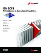
Figure 3-1 shows a typical GDPS Metro single-site workload configuration. LPARs P1 and P2 are in the production sysplex, as are the coupling facilities CF1, CF2, and CF3. The primary (RS1) disks are in Site1, with a set of secondaries (RS2) also in Site1 and another set of secondaries (RS3) in Site2. All the production systems are running in Site1, with only the GDPS controlling system (K1) running in Site2. You will notice that system K1’s disks (those marked K1) are also in Site2 and are not mirrored.
The GDPS Metro code itself runs under NetView and System Automation, and runs in every system in the GDPS sysplex.
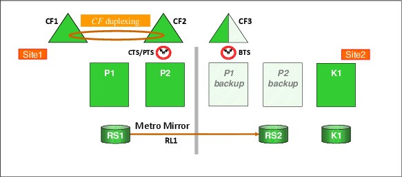
Figure 3-1 GDPS Metro single site workload configuration
3.2.3 Multisite workload configuration
A multisite workload configuration, shown in Figure 3-2, differs from a single-site workload in that production systems are running in both sites. Although, running a multisite workload as a base sysplex is possible, seeing this configuration as a base sysplex (that is, without coupling facilities) is unusual. This is because a multisite workload is usually a result of higher availability requirements, and Parallel Sysplex and data sharing are core components of such an environment.
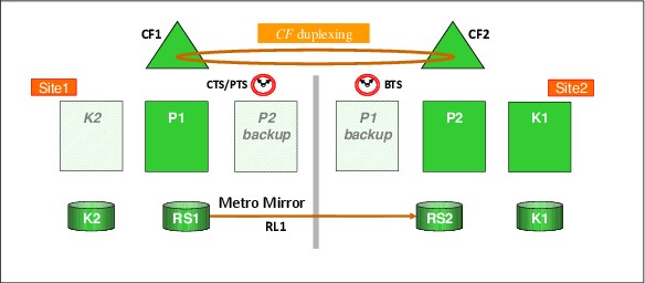
Figure 3-2 GDPS Metro multisite workload configuration
Because in this example we have production systems in both sites, we need to provide the capability to recover from a failure in either site. So, in this case, there is also a GDPS controlling system with its own local (not mirrored) disk running in Site1, namely System K2. Therefore, if there is a disaster that disables Site2, there will still be a GDPS controlling system available to decide how to react to that failure and what recovery actions are to be taken.
3.2.4 Business Recovery Services configuration
A third configuration is known as the Business Recovery Services (BRS) configuration, and is shown in Figure 3-3 on page 74. In this configuration, all the systems in the GDPS configuration, including the controlling systems, are in a sysplex in the same site, namely Site1. The sysplex does not span the two sites. The second site, Site2, might be a client site or might be owned by a third-party recovery services provider; thus the name BRS.
Site2 contains the secondary disks and the alternate couple data sets (CDS), and might also contain processors that will be available in case of a disaster, but are not part of the configuration. This configuration can also be used when the distance between the two sites exceeds the distance supported for a multisite sysplex, but is within the maximum distance supported by FICON and Metro Mirror.
Although there is no need for a multisite sysplex with this configuration, you must have channel connectivity from the GDPS systems to the secondary disk subsystems. Also, as explained in the next paragraph, the controlling system in Site1 needs channel connectivity to its disk devices in Site2. Therefore, FICON link connectivity from Site1 to Site2 is required.
For more information about options that are available to extend the distance of FICON links between sites, see 2.9.7, “Connectivity options” on page 47, and IBM z Systems Connectivity Handbook, SG24-5444.
In the BRS configuration one of the two controlling systems must have its disk devices in Site2. This permits that system to be restarted manually in Site2 after a disaster is declared. After it restarts in Site2, the system runs a GDPS script to recover the secondary disk subsystems, reconfigure the recovery site, and restart the production systems from the disk subsystems in Site2.
If you have only a single controlling system and you have a total cross-site fiber connectivity failure, the controlling system running on Site2 disks might not be able to complete the Freeze operation because it will lose access to its disk in Site2. Having a second controlling system running on Site1 local disks ensures that the freeze operation completes successfully if the controlling system running on Site2 disks is down or cannot function because of a cross-site fiber loss.
GDPS attempts to maintain the current Master system in the controlling system by using the secondary disks (see Figure 3-3).
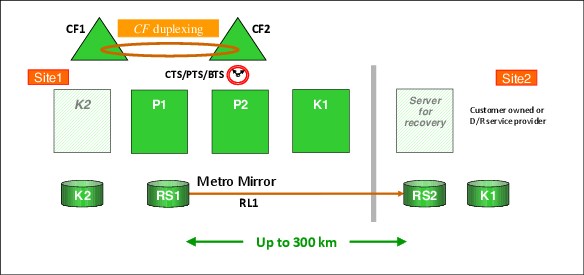
Figure 3-3 GDPS Metro BRS configuration
3.2.5 Single-leg configuration
The previous sections showed GDPS Metro in single-leg configurations. That is, the configurations consisted of only two copies of the production data: a primary copy and a secondary copy. The primary and secondary copies of data are called disk locations or replication sites. The copy in Site1 is known as RS1 and the copy in Site2 is known as RS2.
The replication connection between the replication sites is called a replication leg or simply a leg. A replication leg has a fixed name that is based on the two disk locations that it connects. In a single-leg configuration, there is only one replication leg, called RL1, and it connects the two disk locations RS1 and RS2.
3.2.6 Dual-leg configuration
In addition to providing the single-leg configuration that was described in the previous section, GDPS Metro also uses the IBM MTMM disk mirroring technology to provide a dual-leg configuration which maintains two synchronous secondary copies of your data to provide an additional level of data resiliency.
With a dual-leg configuration, a replication site is added and two replication legs also are added. The three disk locations, or copies, are known as RS1, RS2, and RS3. RS1 and RS2 are assumed to be “local” and are fixed in Site1 an RS3 is fixed in Site2.
Although any of the three replication sites can assume the primary disk role, in a typical configuration:
•The primary disk is in Site1, that is, either RS1 or RS2.
•The other disk copy in Site1 provides high availability or HA protection.
•The copy in Site2 (RS3) provides disaster recovery or DR protection.
The replication legs in a dual-leg configuration have fixed names that again, are based on the two disk locations that they connect:
•The RS1-RS2 (or RS2-RS1) leg is RL1
•The RS1-RS3 (or RS3-RS1) leg is RL2
•The RS2-RS3 (or RS3-RS2) leg is RL3
The name of a given replication leg never changes, even if the replication direction is reversed for that leg. However, the role of a leg can change, depending on the primary disk location. The two legs from the current primary to each of the two secondaries serve as the active legs whereas the leg between the two secondary locations serves as the incremental resync or MTIR leg.
To illustrate this concept, consider the sample dual-leg configuration that is shown in Figure 3-4.
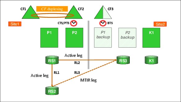
Figure 3-4 Typical GDPS Metro dual-leg configuration
In this sample configuration, RS1 is the primary disk location, RL1 and RL2 are the active replication legs, and RL3 is the MTIR leg.
If a disk switch exists and RS2 becomes the new primary disk, RL1 and RL3 become the active replication legs and RL2 then becomes the MTIR leg, as shown in Figure 3-5.
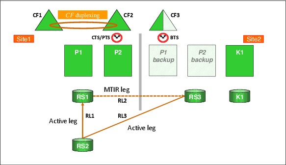
Figure 3-5 GDPS Metro dual-leg configuration following switch to RS2
3.2.7 Combining GDPS Metro with GDPS GM or GDPS XRC
When configured in a single-leg topology, GDPS Metro can be combined with GDPS Global - GM (GDPS GM) or GDPS Global - XRC (GDPS XRC) in 3-site and 4-site configurations. In such configurations, GDPS Metro (when combined with Parallel Sysplex use and HyperSwap) in one region provides continuous availability across a metropolitan area or within the same local site, and GDPS GM or GDPS XRC provide disaster recovery capability using a remote site in a different region.
The 4-site environment is configured in a symmetric manner so that there is a GDPS Metro-managed replication leg available in both regions to provide continuous availability (CA) within the region, with GDPS GM or GDPS XRC to provide cross-region DR, no matter in which region production is running at any time.
Combining GDPS Metro and GDPS GM in this fashion is referred to as GDPS Metro Global - GM (GDPS MGM). Combining GDPS Metro and GDPS XRC in this fashion is referred to as GDPS Metro Global - XRC (GDPS MzGM).
For more information about GDPS MGM and GDPS MzGM configurations, see Chapter 9, “Combining local and metro continuous availability with out-of-region disaster recovery” on page 267.
3.2.8 GDPS Metro in a single site
The final configuration is where you want to benefit from the capabilities of GDPS Metro to extend the continuous availability attributes of a Parallel Sysplex to planned and unplanned disk reconfigurations, but you do not have the facilities to mirror disk across two sites. In this case, you can implement GDPS Metro HyperSwap Manager (GDPS HM).
GDPS HM is similar to the full function GDPS Metro offering, except that it does not include the scripts for management of the LPARs and workloads. GDPS HM is upgradeable to a full GDPS Metro implementation. For more information about GDPS HM, see Chapter 4, “GDPS Metro HyperSwap Manager” on page 113.
Because configuring GDPS HM (or GDPS Metro) within a single site does not provide protection against site failure events, such a configuration is likely to be used within the context of a GDPS MGM or GDPS MzGM multi-site solution rather than a stand-alone solution.
Another possibility is that this is for a client environment that has aggressive recovery time objectives for failures other than a disaster event and some mechanism such as tape vaulting is used for disaster protection. This means that long recovery times and a fair amount of data loss can be tolerated during a disaster.
3.2.9 Other considerations
The availability of the dedicated GDPS controlling system (or systems) in all scenarios is a fundamental requirement in GDPS. Merging the function of the controlling system with any other system that accesses or uses the primary volumes is not possible.
Equally important is that certain functions (stopping and restarting systems and changing the couple data set configuration) are done through the scripts and panel interface provided by GDPS. Because events such as systems going down or changes to the couple data set configuration are indicators of a potential disaster, such changes must be initiated using GDPS functions so that GDPS understands that these are planned events.
3.3 GDPS Metro management of distributed systems and data
Most enterprises today have a heterogeneous IT environment where the applications and data are on various hardware and software platforms, such as IBM Z, IBM System p, UNIX, Windows, and Linux. Such an environment can benefit greatly if a single point of control manages the data across all the platforms, and for the disaster recovery solution to coordinate the recovery across multiple platforms.
In this section, we describe the following functions that are provided by GDPS Metro that are available for clients to manage data and coordinate disaster recovery across multiple platforms:
•Fixed Block disk management
•Multiplatform Resiliency for IBM Z (also known as xDR)
3.3.1 Fixed Block disk management
Most enterprises today run applications that update data across multiple platforms. For these enterprises, there is a need to manage and protect not just the data that is on CKD devices, but also the data that is on FB devices for IBM Z and non IBM Z servers. GDPS Metro provides the capability to manage a heterogeneous environment of IBM Z and distributed systems data through a function that is called Fixed Block Disk Management (FB Disk Management).
The FB Disk Management function allows GDPS to be a single point of control to manage business resiliency across multiple tiers in the infrastructure, which improves cross-platform system management and business processes. GDPS Metro can manage the Metro Mirror remote copy configuration and FlashCopy for distributed systems storage.
Specifically, FB disk support extends the GDPS Metro Freeze capability to FB devices that reside in supported disk subsystems to provide data consistency for the IBM Z data and the data on the FB devices.
With FB devices included in your configuration, you can select one of the following options to specify how Freeze processing is to be handled for FB disks and IBM Z (CKD disks), when mirroring or primary disk problems are detected:
•You can select to Freeze all devices managed by GDPS.
If this option is used, the CKD and FB devices are in a single consistency group. Any Freeze trigger for the IBM Z or FB devices results in the FB and the IBM Z LSSs managed by GDPS being frozen. This option allows you to have consistent data across heterogeneous platforms in the case of a disaster, which allows you to restart systems in the site where secondary disks are located.
This option is especially suitable when distributed units of work are on IBM Z and distributed servers that update the same data; for example, by using the IBM Distributed Relational Database Architecture (IBM DB2 DRDA).
•You can select to Freeze devices by group.
If this option is selected, the CKD devices are in a separate consistency group from the FB devices. Also, the FB devices can be separated into multiple consistency groups; for example, by distributed workloads. The Freeze is performed on only the group for which the Freeze trigger was received. If the Freeze trigger occurs for an IBM Z disk device, only the CKD devices are frozen. If the trigger occurs for a FB disk, only the FB disks within the same group as that disk are frozen.
FB disk management prerequisites
GDPS requires the disk subsystems that contain the FB devices to support the z/OS Fixed Block Architecture (zFBA) feature. GDPS runs on z/OS and therefore communicates to the disk subsystems directly over a channel connection. The z/OS Fixed Block Architecture (zFBA) provides GDPS the ability to send the commands that are necessary to manage Metro Mirror and FlashCopy directly to FB devices over a channel connection. It also enables GDPS to receive notifications for certain error conditions (for example, suspension of an FB device pair). These notifications allow the GDPS controlling system to drive autonomic action such as performing a freeze for a mirroring failure.
|
Note: HyperSwap for FB disks is not supported for any IBM Z or non IBM Z servers.
|
3.3.2 Multiplatform Resiliency for IBM Z
GDPS Metro includes a function known as Multiplatform Resiliency for IBM Z (also known as xDR). This function extends the near-continuous availability and disaster recovery capabilities provided by GDPS Metro to other platforms, or operating systems, running on IBM Z servers.
For example, to reduce IT costs and complexity, many enterprises are consolidating open servers into Linux on IBM Z servers. Linux on IBM Z systems can be implemented as guests that are running under z/VM, as servers that are running natively on IBM Z, or as servers that are running under the KVM Hypervisor on IBM Z. This results in a multitiered architecture in which the application server and the database server are running on different IBM Z platforms. Several examples exist of an application server running on Linux on IBM Z and a database server running on z/OS, including the following examples:
•WebSphere Application Server running on Linux and CICS, DB2 running under z/OS
•SAP application servers running on Linux and database servers running on z/OS
For such multitiered architectures, Multiplatform Resiliency for IBM Z provides a coordinated near-continuous availability and disaster recovery solution for the z/OS and the Linux on IBM Z tiers. It can be implemented if the Linux on IBM Z systems run as guests under z/VM or as servers that are running under the KVM Hypervisor on IBM Z (native Linux on IBM Z systems are not supported) and if the disks being used are CKD disks.
|
Note: For the remainder of this section, Linux on IBM Z is also referred to as Linux. The terms are used interchangeably.
|
Another IBM Z platform that requires coordinated near-continuous availability and disaster recovery protection is known as the IBM Secure Service Container, or SSC platform. The IBM Secure Service Container is a container technology through which you can more quickly and securely deploy firmware and software appliances on IBM Z and IBM LinuxONE (LinuxONE) servers. A Secure Service Container partition (or LPAR) is a specialized container for installing and running specific firmware or software appliances. An appliance is an integration of operating system, middleware, and software components that work autonomously and provide core services and infrastructures that focus on consumability and security.
One such appliance that was deployed by way of an SSC is the IBM Db2 Analytics Accelerator on Z, which is a workload optimized appliance add-on to Db2 for z/OS. It dramatically speeds up queries, and offers a unified homogeneity of service, support, and operations and deeper integration with operational processes. Multiplatform Resiliency for IBM Z provides a coordinated near-continuous availability and disaster recovery solution for the IBM Db2 Analytics Accelerator on Z as a priced feature of GDPS Metro.
In this section, we describe the following functions that are provided by GDPS Metro that are available for clients to coordinate disaster recovery across multiple IBM Z platforms:
•Multiplatform Resiliency for z/VM
•Multiplatform Resiliency for KVM
•Multiplatform Resiliency for IBM Db2 Analytics Accelerator on Z
Multiplatform Resiliency for z/VM
Protecting data integrity across multiple platforms
z/VM provides a HyperSwap function. With this capability, the virtual device that is associated with one real disk can be swapped transparently to another disk. GDPS Metro coordinates planned and unplanned HyperSwap for z/OS and z/VM disks, which provides continuous data availability spanning the multitiered application. It does not matter whether the first disk failure is detected for a z/VM disk or a z/OS disk; all are swapped together.
For site failures, GDPS Metro provides a coordinated Freeze for data consistency across z/VM and z/OS. Again, it does not matter whether the first freeze trigger is captured on a z/OS disk or a z/VM disk; all are frozen together.
|
Note: Most xDR functions, including HyperSwap, benefit non-Linux guests of z/VM also. In fact, having no “production” Linux guests at all is possible. The only requirement for Linux guests is for the xDR proxy nodes, which must be dedicated Linux guests.
However, be aware that a z/VM host running z/OS guests is not supported by xDR.
|
GDPS xDR configuration
In a GDPS xDR-managed z/VM system you must configure a special Linux guest, which is known as the proxy guest. The proxy is a guest that is dedicated to providing communication and coordination with the GDPS Metro controlling system. It must run System Automation for Multiplatforms (SA MP) with the separately licensed xDR feature.
The proxy guest serves as the middleware for GDPS. It communicates commands from GDPS to z/VM, monitors the z/VM environment, and communicates status information and failure information, such as a HyperSwap trigger that is affecting z/VM disk back to the GDPS Metro controlling system. GDPS Metro uses SA MP to pass commands to z/VM and Linux guests.
GDPS xDR supports definition of two proxy nodes for each z/VM host: one proxy node running on Site1 disk and the other running on Site2 disk. This support extends the two-controlling system model to the xDR proxy nodes, so it provides a high-availability proxy design. At any particular time, the proxy node running on disk in the Metro Mirror secondary site is the Master proxy, and this is the proxy node that the GDPS Master controlling system coordinates actions with. Similar to the controlling system Master role, the proxy node Master role is switched automatically when Metro Mirror disk is switched (or recovered) or when the Master proxy fails.
It is not mandatory to have any z/OS production systems managed by GDPS. The only z/OS systems that are mandatory are the GDPS controlling systems. Originally, xDR supported only one GDPS Controlling system (also referred to as the GDPS Master K-sys).
xDR functions were able to be processed only by the single GDPS Master K-sys. In the event of a planned or unplanned outage of the GDPS Master K-sys, the current Master function switched to a production system but xDR processing was interrupted, because production systems cannot perform xDR functions.
xDR now supports two GDPS Controlling systems. If your SA MP xDR environment is configured to support two GDPS Controlling systems, xDR processing is protected in the event of a planned or unplanned outage of the Controlling system that is the current Master. This is because the alternate Controlling system takes over the current Master responsibility and the alternate Controlling system can perform xDR functions.
Also, if an autonomic Master switch as a result of a disk swap occurs, xDR functions are protected because the alternate Master is a Controlling system and can manage xDR resources.
During cluster initialization, the proxy and non-proxy nodes send their initialization signal to both GDPS Controlling systems. Only the GDPS system that is the current Master responds to the initialization signal, and this is how the Linux nodes know which of the Controlling systems is the current Master. Certain events (such as heartbeating and communication of an I/O error) are sent to the current Master; certain other events (such as initialization) are communicated to both Controlling systems.
In the event of a Master K-sys switch, GDPS informs the Linux nodes of the switch and the Linux nodes then resume relevant communications with the new Master K-sys.
We strongly suggest that you run GDPS with two Controlling systems and enable xDR to support two Controlling systems.
Figure 3-6 shows an xDR configuration with two GDPS Controlling systems following a HyperSwap of the primary disks from Site1 to Site2. The Master K-sys was moved to K2-sys in Site1. xDR functions can still be performed by K2-sys; for example, a subsequent disk failure in Site2.
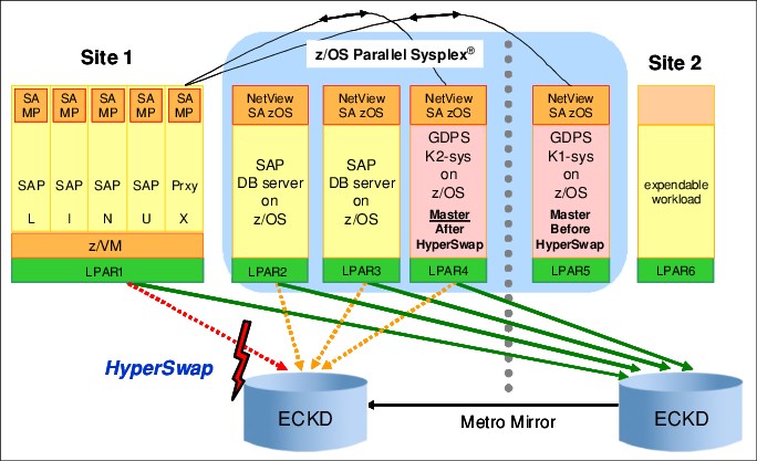
Figure 3-6 xDR configuration with two Controlling systems after a HyperSwap
Also in Figure 3-6 on page 80, several Linux nodes are running as guests under z/VM. One of the Linux guests is the proxy. The non-proxy SAP Linux guests are shown as also running SA MP. This is not mandatory. If you do run SA MP in the production Linux guest systems, GDPS provides additional capabilities for such guests.
Disk and LSS configuration
The disks being used by z/VM, the guest machines, and the proxy guest in this configuration must be CKD disks. GDPS xDR support allows for the definition of the Metro Mirror secondary devices configured to z/VM and the guest machines to be defined in an alternate subchannel set1. This can simplify definitions and provide high scalability for your disk configuration. For more information, see “Addressing z/OS device limits in a GDPS Metro environment” on page 25.
GDPS xDR also supports the sharing of a logical disk control unit (LSS) by multiple z/VM systems. This facilitates the efficient sharing of resources, provides configuration flexibility, and simplifies the setup that would be required to keep the LSSs separate. It also enables xDR environments to use the z/VM Cross System Extension (CSE) capability.
For example, suppose you have more than one z/VM system and want to perform the following tasks:
•Share the IBM RACF® database across your systems.
•Manage one VM Directory for all the systems.
•Ensure that a minidisk is linked only RW on one guest on one system, and have all the systems enforce that.
•Share the z/VM System Residence volumes.
z/VM CSE can perform all of these tasks for you. The z/VM CSE enables you to treat separate VM systems as a single system image, which lowers your system management workload and provides higher availability. For more information about CSE, see z/VM CP Planning and Administration, SC24-6083.
If you want to share LSSs and disks, consider the following points:
•In one LSS, you can place disks for as many xDR-managed z/VM systems as you want.
•If you want, any z/VM disk that is managed by GDPS can be shared by multiple xDR-managed z/VM systems. This requires that you also implement z/VM CSE.
Serialization for disk is supported through the Reserve/Release mechanism for minidisks under z/VM control.
In addition to various z/VMs sharing an LSS, having z/OS and z/VM disks in the same LSS is possible. This configuration allows the LSS capacity to be split between z/OS and z/VM and, with the use of hardware reserves, individual disks can be shared by z/VM and z/OS systems.
System and hardware management
System and hardware management capabilities that are similar to those available for z/OS systems are also available for z/VM systems. GDPS xDR can perform a graceful shutdown of z/VM and its guests and perform hardware actions, such as LOAD and RESET against the z/VM system’s partition. GDPS supports taking a stand-alone dump of a z/VM system and, in the event of a HyperSwap, it automatically switches the pointers of the z/VM dump volumes to the swapped to site. GDPS can manage CBU/OOCoD for IFLs and CPs on which z/VM systems are running.
GDPS controlled shutdown of z/VM
Graceful shutdown of a z/VM system involves multiple virtual servers. This is a complex process and GDPS has special automation to control this shutdown. The GDPS automated process occurs in multiple phases:
•During the first phase, all the SA MP clusters with all the nodes for these clusters are stopped. The master proxy is the only guest running SA MP that is not stopped. When all clusters and nodes running SA MP are successfully stopped, GDPS proceeds to the next phase.
•During the second phase, all remaining guests that are capable of processing the shutdown signal are stopped.
•In phase three, the master proxy server and z/VM are shut down.
When an xDR-managed z/VM system is shut down by using the GDPS Stop Standard Action (or equivalent script statement), all xDR-managed guests are stopped in parallel. GDPS provides the ability to control the sequence in which you stop guest systems during a z/VM shutdown.
GDPS Metro xDR support for z/VM Single System Image clustering
z/VM introduced Single System Image (SSI) clustering whereby four z/VM systems can be clustered to provide more effective resource sharing and other capabilities.
GDPS xDR supports z/VM systems that are members of an SSI cluster. GDPS are aware of the fact that a z/VM system is a member of an SSI. This allows GDPS to perform certain system control actions for these z/VM systems correctly while observing SSI rules.
Linux guests can be transparently moved from one z/VM system in an SSI cluster to another; that is, without requiring the guest to be stopped. This capability, which is called Live Guest Relocation, provides continuous availability for Linux guests of z/VM in planned outage situations. If a z/VM system is going to be shut down, for disruptive software maintenance for example, the relocatable Linux guests can first be moved to other z/VM systems in the cluster to avoid an outage to these guests. Similarly, for an entire site shutdown, the guests under all z/VM systems in the site to be shut down can first be moved to z/VM systems in the other site.
GDPS provides support for performing Live Guest Relocation for xDR-managed z/VM systems. GDPS provides a relocation test capability that tries to assess whether a particular relocation action is likely to be successful. For example, the target z/VM system might not have sufficient resources to host the guest to be moved. Such a test function is quite useful because it allows you to rectify potential problems before they are encountered. GDPS management for CPs and IFLs using On/Off Capacity on Demand is complementary to this function. You can use GDPS to first increase IFL capacity on the target CEC before performing the actual move.
GDPS xDR support for z/VSE guests of z/VM
GDPS provides specific support for z/VSE guest systems. GDPS monitoring of z/VSE guests requires z/VSE 5.1 with the GDPS Connector (also known as the GDPS Client) enabled for GDPS monitoring. z/VSE guests of xDR-managed z/VM systems can be enabled for special GDPS xDR monitoring and management:
•GDPS can detect the failure of a z/VSE guest and automatically restart it.
•z/VSE guests can be gracefully shut down as part of the graceful shutdown of the hosting z/VM system initiated by GDPS.
GDPS xDR support for Red Hat OpenShift Container Platform (RHOCP)
GDPS supports the Red Hat OpenShift Container Platform (RHOCP) V4.7.13 application environment like any other z/VM LPAR based application workload. GDPS xDR supports RHOCP hosted on z/VM guests on a z/VM SSI running on CKD DASD, without persistent storage.
Customization Verification Program
The xDR Customization Verification Program (CVP) verifies that installation and customization activities were done correctly for Linux on IBM Z environments. This helps identify any issues with the customization of the environment where many components exist with quite specific setup and customization requirements. It also helps identify aspects of the xDR customization that do not adhere to preferred practices recommendations.
CVP is an operator-initiated program that can be used after initial setup, and periodically thereafter, to ensure that changes to the environment have not broken the xDR setup. Two separate programs are provided: One to run on the controlling systems and another to run on the Linux server to ensure that both ends of the implementation are verified.
xDR Extended Monitoring
The GDPS HyperSwap Monitor provides checking for z/OS systems to ascertain whether the z/OS systems that are managed by GDPS meet required conditions. Any system that does not meet the required conditions is marked as “not HyperSwap-ready.” A planned HyperSwap is not allowed to execute unless all systems are HyperSwap-ready. If an unplanned swap is triggered, systems that are not HyperSwap-ready are reset and the swap is performed with the participation of only those systems that are HyperSwap-ready.
GDPS also performs similar HyperSwap monitoring for xDR systems. Several environmental conditions that are required for HyperSwap for xDR systems are checked. If an xDR system does not meet one or more environmental conditions, GDPS attempts to autonomically fix the detected issue. If it is not possible to autonomically fix the issue, alerts are raised.
Also, any such xDR system that does not meet all environmental conditions that are monitored are marked as “not HyperSwap-ready.” Raising alerts during monitoring allows an installation to act on the alert and to fix the reported problems in a timely manner to avoid having the system reset if an unplanned swap is triggered.
Multiplatform Resiliency for KVM
In this section, we discuss protecting data integrity across platforms and multiplatform resiliency for KVM configurations.
Protecting data integrity across multiple platforms
KVM does not provide a HyperSwap function. However, GDPS Metro coordinates planned and unplanned HyperSwap for z/OS, Linux under z/VM and Linux under KVM CKD disks to maintain data integrity and control the shutdown and re-start in place of the KVM LPARs. For disk or site failures, GDPS Metro provides a coordinated Freeze for data consistency on CKD disk across KVM, z/VM and z/OS.
Multiplatform resiliency for KVM configuration
Multiplatform Resiliency for KVM uses the xDR protocol to communicate with an xDR KVM proxy to send Libvirt commands; therefore, xDR must be enabled in GDPS to support KVM. The xDR KVM Proxy is delivered as a Linux RPM for SLES or a DEB package for Ubuntu. The proxy guest serves as the middleware for GDPS. It communicates commands from GDPS to KVM, monitors the KVM environment, and communicates status information back to the GDPS Metro controlling system.
Figure 3-7 shows a GDPS Metro configuration with a mix of z/OS, Linux on z/VM and Linux on KVM, all being managed by a single GDPS.
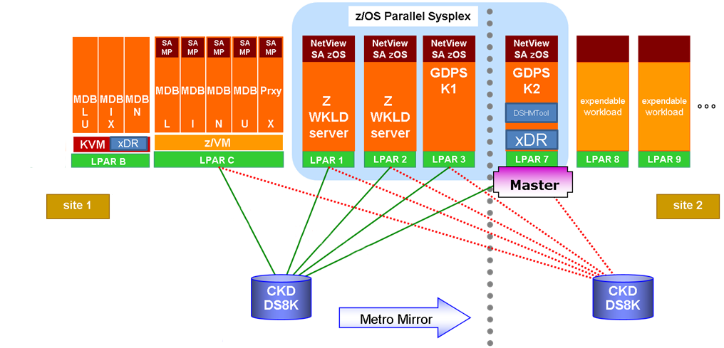
Figure 3-7 Multiplatform Resiliency for KVM
System and hardware management
System and hardware management capabilities similar to those available for z/OS systems are also available for KVM systems. GDPS Metro Multiplatform Resiliency for KVM provides support for:
• IBM z15®, z14®, z13®, EC12, BC12 systems.
• LinuxONE Emperor and RockHopper Systems (based on IBM PR/SM BCPII support, not PR/SM 2's DPM).
•Planned switch (graceful shutdown and startup, or re-IPL in place) for VMs and/or the KVM hypervisor.
•Unplanned takeover (coordinated takeover and recovery) for VMs, and/or the KVM hypervisor.
•VM workload startup will be handled via guest Linux OS autostart policy and will be managed outside of GDPS.
Multiplatform Resiliency for KVM uses GDPS PR/SM BCPII commands and GDPS script statements for LPAR management. It does not use DPM on LinuxONE; only the PR/SM BCPII interface is used for LPAR management.
For remote management of KVM and its guests, Multiplatform Resiliency for KVM uses Libvirt commands, which are run by calling libvirt virsh commands from an xDR proxy that is running in the KVM Linux instance.
KVM HyperSwap status
The GDPS HyperSwap Monitor provides checking for z/OS systems to ascertain whether the z/OS systems that are managed by GDPS meet the required conditions for HyperSwap. Any z/OS system that does not meet the required conditions is marked as “not HyperSwap-ready.”
A planned HyperSwap is not allowed to run unless all systems are HyperSwap-ready. If an unplanned swap is triggered, systems that are not HyperSwap-ready are reset and the swap is performed with the participation of only those systems that are HyperSwap-ready. Remember that KVM does not support HyperSwap and so always has a HyperSwap status of INHIBITED. Therefore, all KVM systems must be shutdown before a planned HyperSwap.
Summary
The Multiplatform Resiliency for KVM function of GDPS can provide a single point of control to monitor and manage Linux systems that are running under the KVM Hypervisor on IBM Z alongside z/OS systems and other Linux systems that are running under z/VM. It can also provide coordinated failover for planned and unplanned events that can affect any of the KVM, z/VM, or z/OS resources. In short, you can achieve business resiliency across your entire enterprise.
Multiplatform Resiliency for IBM Db2 Analytics Accelerator on Z
In this section, we discuss xDR for IBM Db2 Analytics Accelerator on a Z configuration.
xDR for IBM Db2 Analytics Accelerator on Z configuration
Figure 3-8 shows a GDPS Metro configuration with an IBM Db2 Analytics Accelerator on Z SSC.
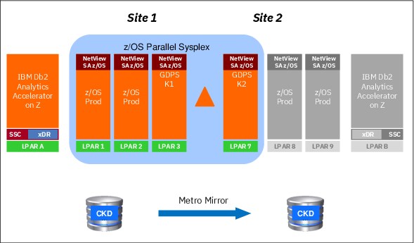
Figure 3-8 Multiplatform Resiliency for IBM Db2 Analytics Accelerator on Z
GDPS Metro supports IBM Db2 Analytics Accelerator on Z in Active/Passive mode. Active/Passive mode means only one active instance exists of IBM Db2 Analytics Accelerator on Z at any time (LPAR A in Figure 3-8). A backup LPAR also is available at the DR site to take over the IBM Db2 Analytics Accelerator on Z workload if a disaster occurs at the primary site (LPAR B in Figure 3-8).
GDPS Metro uses the xDR protocol to communicate with the IBM Db2 Analytics Accelerator on Z SSC. An xDR agent, running on the SSC, serves as the middleware for GDPS. It communicates commands from GDPS to the SSC, monitors the SSC environment, and communicates status information back to the GDPS Metro controlling system.
Disk configuration and replication management
The disk devices that are used by the IBM Db2 Analytics Accelerator on Z are defined to GDPS, which enabling GDPS to manage Metro Mirror for those devices. The disks that are being used by the IBM Db2 Analytics Accelerator on Z must be CKD disks.
GDPS xDR support allows for the definition of the Metro Mirror secondary devices that are configured to the IBM Db2 Analytics Accelerator on Z to be defined in an alternative subchannel set2. This can simplify definitions and provide high scalability for your disk configuration. For more information, see “Addressing z/OS device limits in a GDPS Metro environment” on page 25.
Protecting data integrity across multiple platforms
The HyperSwap function is not available for IBM Db2 Analytics Accelerator on Z. However, GDPS Metro provides coexistence for planned and unplanned HyperSwap events.
For planned HyperSwap, the user-written script that performs the operation must first shutdown the IBM Db2 Analytics Accelerator on Z LPARs and re-start them in place after the HyperSwap is complete. For an unplanned HyperSwap, GDPS Metro provides takeover scripts that get control after an unplanned HyperSwap occurs. These takeover scripts can be used to automatically restart the IBM Db2 Analytics Accelerator on Z LPARs, which were reset by the unplanned HyperSwap operation.
In either case, GDPS Metro coordinates the operation across the CKD disks for all of the systems in the GDPS configuration, whether they be z/OS systems, Linux systems running under z/VM or KVM, or IBM Db2 Analytics Accelerator on Z systems,. This configuration maintains data consistency across the entire environment.
For site failures, GDPS Metro provides a coordinated Freeze across the CKD devices for all of the systems in the configuration to provide a consistent copy of data on the secondary devices to enable recovery.
System and hardware management
The IBM Db2 Analytics Accelerator on Z SSC LPAR is also defined to GDPS, which enables GDPS to manage the IBM Db2 Analytics Accelerator on Z system.
System and hardware management capabilities that are similar to those available for z/OS systems are also available for IBM Db2 Analytics Accelerator on Z SSC LPARs. Capabilities are provided for the following tasks:
•Stop the IBM Db2 Analytics Accelerator on Z system
•Reset the IBM Db2 Analytics Accelerator on Z system
•Activate the IBM Db2 Analytics Accelerator on Z SSC LPAR
•Deactivate the IBM Db2 Analytics Accelerator on Z SSC LPAR
•Query the status of the IBM Db2 Analytics Accelerator on Z
These capabilities enable you to manage the IBM Db2 Analytics Accelerator on Z system from the GDPS Standard Actions panel and to automate the following workflows:
•Planned site switch to Site 2
•Unplanned failover to Site 2, which is triggered by an IBM Db2 Analytics Accelerator on Z system failure
•Unplanned failover to Site2, which is triggered by a PPRC primary problem
•Unplanned freeze of PPRC mirroring, which is triggered by a PPRC mirroring problem
•Return home to Site 1 as a planned action
•Disaster recovery testing
GDPS xDR for IBM Db2 Analytics Accelerator on Z uses PR/SM BCPII commands and IBM Z Hardware Management Console Web Services API requests for managing the SSC LPAR. Therefore, the GDPS Metro controlling systems must be configured to enable communications for these interfaces.
3.4 Managing z/OS systems outside of the GDPS sysplex
In 3.1.4, “Protecting other CKD data” on page 68, we describe a method that allows GDPS to monitor and manage Metro Mirror on behalf of systems that are not running in the GDPS sysplex. We refer to such non-GDPS systems outside of the sysplex as foreign systems and we refer to the disk of these systems as foreign disk.
Managing foreign systems and the foreign disk by using the method that is described in 3.1.4, “Protecting other CKD data” on page 68 has a key limitation in that this method does not support HyperSwap for the foreign systems.
Although the foreign disks are included in the swap scope, the foreign systems are required to be stopped before a planned swap and are denied access to the swapped-from disks by hanging on the Extended Long Busy (and/or by the Soft Fence established by GDPS) as a result of an unplanned swap after, which they (the foreign systems) must be reset and reloaded from the swapped-to disk.
However, GDPS Metro provides a feature that is known as the z/OS Proxy that extends the near continuous availability protection of HyperSwap to z/OS systems that are running outside of the GDPS sysplex. This includes stand-alone z/OS systems (MONOPLEX or XCFLOCAL) and systems that are running in a multi-system sysplex other than the GDPS sysplex.
In a z/OS Proxy environment, a GDPS Metro agent runs in each of the z/OS Proxy-managed systems that are outside of the GDPS sysplex. This agent, known as the z/OS Proxy, communicates with the Master GDPS controlling system, which facilitates coordinated planned and unplanned HyperSwap, and coordinated freeze processing across the systems in the GDPS sysplex and all z/OS systems that are managed by the z/OS Proxy.
In addition to Metro Mirror, Freeze and HyperSwap management, much of the hardware management (for example, automated system resets and IPLs) of the z/OS Proxy-managed systems is provided. However, some GDPS Metro functions, such as the CDS and CF management functions for z/OS Proxy-managed systems running in foreign sysplexes, are not available.
Figure 3-9 shows a basic configuration to help explain the support that GDPS provides in monitoring and managing the z/OS Proxy-managed systems and the mirrored disks that are used by these systems.
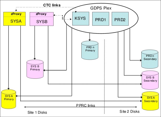
Figure 3-9 Sample z/OS Proxy Environment
As shown in Figure 3-9, the traditional GDPS sysplex environment consists of production systems PRD1 and PRD2 and the controlling system KSYS. The primary disks for these GDPS production systems in Site1 are mirrored to Site2 using Metro Mirror. This environment represents a standard GDPS Metro installation.
The systems SYSA and SYSB are z/OS Proxy-managed systems. They are outside of the GDPS sysplex and do not run GDPS NetView or System Automation code. Instead, they run the z/OS Proxy agent which communicates and coordinates actions with the Master GDPS controlling system.
The z/OS Proxy-managed systems are connected to the controlling systems via FICON Channel-to-Channel connections.
The z/OS Proxy-managed systems do not need host attachment to the disks that belong to the systems in the GDPS sysplex and do not need to define those disks. However, the systems in the GDPS sysplex do need to have UCBs for and have host channel attachment to, all Metro Mirrored disk, their own and all disks that belong to the z/OS Proxy-managed disks.
3.4.1 z/OS Proxy disk and disk subsystem sharing
The mirrored disk attached to the z/OS Proxy-managed systems can be on separate physical disk subsystems or in the same physical disk subsystems as the disk belonging to the systems in the GDPS sysplex. Mirrored disks for the systems in the GDPS sysplex and the z/OS Proxy-managed systems can also be co-located in the same LSS.
Because hardware reserves are now allowed in a GDPS HyperSwap environment, GDPS systems and z/OS Proxy-managed systems can share the GDPS-managed Metro Mirrored disks. Systems in the GDPS sysplex can share disks among themselves more efficiently by converting reserves to global enqueues and this configuration is recommended for devices that are shared only within the GDPS sysplex. Similarly, systems in any foreign sysplex can share disks with each other if reserves in the foreign sysplex are converted to global enqueues.
3.5 Managing the GDPS environment
We saw how GDPS Metro can protect almost any type of data that can be in a disk subsystem. It can also provide data consistency across multiple platforms. However, as discussed in Chapter 1, “Introduction to business resilience and the role of GDPS” on page 1, most IBM Z outages are not disasters. Instead, they are planned outages, with a small percentage of unplanned outages.
In this section, we describe the other aspect of GDPS Metro; that is, its ability to monitor and manage the resources in its environment. GDPS provides several mechanisms to help you manage the GDPS sysplex and resources within that sysplex. These mechanisms include user interfaces, scripts, and APIs. We review these mechanisms and provide more information about the management of the GPS environment in the following sections.
3.5.1 User interfaces
Two primary user interface options are available for GDPS Metro: The NetView 3270 panels and a browser-based graphical user interface (also referred to as the GUI or the GDPS GUI in this book).

Figure 3-10 Main GDPS Metro 3270-based panel
The panel that is shown in Figure 3-10 includes a summary of configuration status at the top, and a menu of selectable choices. As an example, to view the disk mirroring (Dasd Remote Copy) panels, enter 1 at the Selection prompt, and then, click Enter.
GDPS graphical user interface
The GDPS GUI is a browser-based interface that is designed to improve operator productivity. The GDPS GUI provides the same functional capability as the 3270-based panel, such as providing management capabilities for Remote Copy Management, Standard Actions, Sysplex Resource Management, SDF Monitoring, and browsing the CANZLOG by using simple point-and-click procedures. Advanced sorting and filtering is available in most of the views that are provided by the GDPS GUI. In addition, users can open multiple windows or tabs to allow for continuous status monitoring, while performing other GDPS Metro management functions.
The GDPS GUI is available in stand-alone GDPS Metro environments and GDPS MGM 3-site and 4-site environments (for more information about GDPS MGM 3-site and 4-site environments, see Chapter 9, “Combining local and metro continuous availability with out-of-region disaster recovery” on page 267).
The GDPS GUI display has four main sections:
•The application header at the top of the page that provides an Actions button for carrying out a number of GDPS tasks, along with the help function and the ability to logoff or switch between target systems.
•The application menu that is down the left side of the window. This menu gives access to various features and functions that are available through the GDPS GUI.
•The active window that shows context-based content, depending on the selected function. This tabbed area is where the user can switch context by clicking a different tab.
•A status summary area that is shown at the bottom of the display.
|
Note: For the remainder of this section, only the GDPS GUI is shown to illustrate the various GDPS management functions. The equivalent traditional 3270 panels exist but are not shown here.
|
The initial status window (known as the dashboard) of the GDPS Metro GUI is shown in Figure 3-11. This window provides an instant view of the status and direction of replication, HyperSwap status, and systems and systems availability. Hovering over the various icons provides more information through pop-up windows.
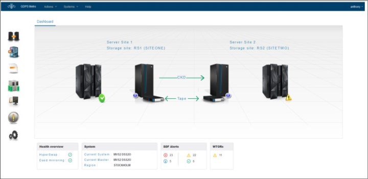
Figure 3-11 GDPS GUI initial window
Monitoring function: Status Display Facility
GDPS also provides many monitors to check the status of disks, sysplex resources, and so on. Any time there is a configuration change, or something in GDPS that requires manual intervention, GDPS raises an alert. GDPS uses the Status Display Facility (SDF) that is provided by System Automation as the primary status feedback mechanism for GDPS.
GDPS provides a dynamically updated window, as shown in Figure 3-12. There is a summary of all current alerts at the bottom of each window. The initial view that is presented is for the SDF trace entries so you can follow; for example, script execution. Click one of the icons representing the other alert categories to view the different alerts that are associated with automation or remote copy in either site, or click All to see all alerts. You can sort and filter the alerts based on several fields presented, such as severity.
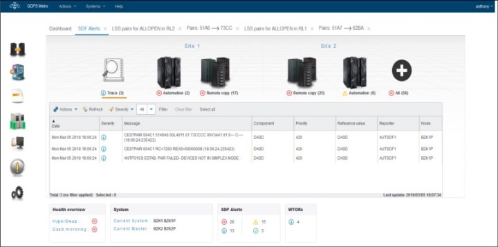
Figure 3-12 GDPS GUI SDF window
The GDPS GUI refreshes the alerts automatically every 10 seconds by default. As with the 3270 panel, if there is a configuration change or a condition that requires special attention, the color of the fields will change based on the severity of the alert. By pointing to and clicking any of the highlighted fields, you can obtain detailed information regarding the alert.
The color of the fields will change based on the severity of the alert. By pointing to and clicking any of the highlighted fields, you can obtain detailed information regarding the alert.
Remote copy windows
The z/OS Advanced Copy Services capabilities are powerful, but the native command-line interface (CLI), z/OS TSO, and ICKDSF interfaces are not as user-friendly as the DASD remote copy panels are. To more easily check and manage the remote copy environment, use the DASD remote copy windows that are provided by GDPS.
For GDPS to manage the remote copy environment, you must first define the configuration (primary and secondary LSSs, primary and secondary devices, and PPRC links) to GDPS in a file called the GEOPARM file. This GEOPARM file can be edited and introduced to GDPS directly from the GDPS GUI.
After the configuration is known to GDPS, you can use the GUI to check that the current configuration matches the one you want. You can start, stop, suspend, and resynchronize mirroring and you can perform these actions at the device level, the LSS level, or both.
You can also manage the PPRC links dynamically, which means you do not have to update the GEOPARM file and then initiate the process to load a new DASD configuration. This is helpful because you may need to temporarily add PPRC links to handle an increase in update activity, or you may need to remove failing PPRC links that can cause significant mirroring delays and with the capability to dynamically manage the links, you can make these changes while avoiding the temporary disruption to storage availability (HyperSwap) that happens when a new DASD configuration is loaded.
Figure 3-13 shows the mirroring window for CKD devices at the LSS level.
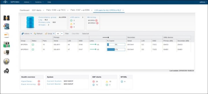
Figure 3-13 GDPS GUI DASD Remote Copy: LSS-level detail window
The top section of the DASD Remote Copy LSS-level window summarizes the number of LSS pairs and their status, including their mirroring status, in the selected consistency group.
The middle section of the window contains a table with one row for each LSS pair in the selected consistency group. In addition to the rows for each LSS, there is a header row containing an Action menu, which enables you to carry out the various DASD management tasks, and a filter menu, which enables you to filter the information presented.
To perform an action on a single LSS-pair (SSID-pair), double-click a row in the table. The frame that is shown in Figure 3-14 is then displayed. The table in this frame shows each of the mirrored device pairs within a single LSS-pair, along with the current status of each pair. In this example, one of the pairs is fully synchronized and in duplex status and the rest of the pairs are in pending status, as summarized in the top section of the window. More information can be viewed for each pair by double-clicking the row, or by selecting the row with a single click and then selecting Query from the Actions menu.
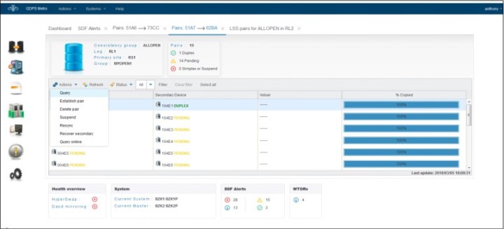
Figure 3-14 GDPS GUI DASD Remote Copy: Device-level detail window
If you are familiar with using the TSO or ICKDSF interfaces, you might appreciate the ease of use of the DASD remote copy panels.
Remember that the GUI that is provided by GDPS is not intended to be a remote copy monitoring tool. Because of the overhead that is involved in gathering the information for every device to populate the windows, GDPS gathers this data only on a timed basis, or on demand following an operator instruction. The normal interface for finding out about remote copy status or problems is the Status Display Facility (SDF).
Standard Actions
GDPS provides facilities to help manage many common system-related planned actions. There are two reasons to use the GDPS facilities to perform these actions known as Standard Actions:
•They are well tested and based on IBM preferred procedures.
•Using the GDPS interface lets GDPS know that the changes that it is seeing (for example, a system being partitioned out of the sysplex) are planned changes, and therefore GDPS will not react to these events.
Standard Actions are single-step actions and are intended to impact only one resource. Examples are starting a system IPL, maintaining the various IPL address and load parameters that can be used to IPL a system, selecting the IPL address and load parameters to be used the next time a system IPL is performed, or activating/deactivating an LPAR.
If you want to stop a system, change its IPL address, then perform an IPL, you start three separate Standard Actions, one after the other. GDPS scripting, as described in 3.5.2, “GDPS scripts” on page 96, is a facility that is suited to multi-step, multi-system actions.
The GDPS Metro Standard Actions GUI window is shown in Figure 3-15. It displays all the systems that are managed by GDPS Metro. It shows the current status and various IPL information for each system. To perform actions on a given system, select the row with a single click and then, select the wanted action from the Actions menu. 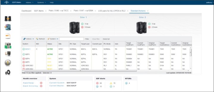
Figure 3-15 GDPS GUI Standard Actions window
GDPS supports taking a stand-alone dump using the GDPS Standard Actions window. Clients using GDPS facilities to perform HMC actions no longer need to use the HMC for taking stand-alone dumps.
Sysplex resource management
There are certain resources that are vital to the health and availability of the sysplex. In a multisite sysplex, it can be quite complex trying to manage these resources to provide the required availability while ensuring that any changes do not introduce a single point of failure.
The GDPS Metro Sysplex Resource Management window, as shown in Figure 3-16 on page 96, provides you with the ability to manage the sysplex resources without having knowledge about where the resources exist. Click the resource type (couple data sets or coupling facilities) to open a panel to manage each resource type.
For example, normally you have Primary Couple Datasets (CDS) in Site1, and your alternates in Site2. However, if you will be shutting down Site1, you still want to have a Primary and Secondary set of CDS, but both must be in Site2. The GDPS Sysplex Resource Management panels provide this capability, without you having to know specifically where each CDS is located.
GDPS also provides facilities to manage the coupling facilities (CFs) in your sysplex. These facilities allow for isolating all of your structures in the CF or CFs in a single site and returning to your normal configuration with structures spread across (and possibly duplexed across) the CFs in the two sites.
The maintenance mode switch allows you to start or stop maintenance mode on a single CF (or multiple CFs, if all selected CFs are in the same site). DRAIN, ENABLE, and POPULATE function is still available for single CFs.
Managing your sysplex resources can also be accomplished through GDPS scripts, which provides an automated means for managing CDSs and CFs for planned and unplanned site or disk subsystem outages. For more information about GDPS scripting capability, see 3.5.2, “GDPS scripts” on page 96.
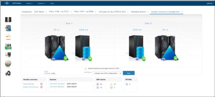
Figure 3-16 GDPS GUI Sysplex Resource Management window
3.5.2 GDPS scripts
At this point, we showed how the GDPS GUI and the GDPS 3270-based panels provide powerful functions to help you manage GDPS resources. However, using GDPS panels is only one way of accessing this capability. Especially when you need to initiate what might be a complex, compound, multistep procedure involving multiple GDPS resources, it is much simpler to use a script which, in effect, is a workflow.
Nearly all of the main functions that can be initiated through the GDPS panels are also available using GDPS scripts. Scripts also provide additional capabilities that are not available using the panels.
A “script” is a procedure, written by you, that pulls together one or more GDPS functions. Scripts can be initiated manually for a planned activity through the GDPS GUI or panels (using the Planned Actions interface), automatically by GDPS in response to an event (HyperSwap), or through a batch interface. GDPS performs the first statement in the list, checks the result, and only if it is successful, proceeds to the next statement. If you perform the same steps manually, you would have to check results, which can be time-consuming, and initiate the next action. With scripts, the process is automated.
Automating complex tasks sometimes can require scripts to contain numerous steps and these scripts can run for significant amounts of time. This issue increases the possibility that a running script might need to be stopped intentionally or fail unexpectedly because of unusual environmental conditions, for example.
To maximize efficiency in these cases, GDPS keeps track of how far a script progressed. If a script fails or is stopped manually, the script can be restarted at the suitable point, which eliminates unnecessary duplicate processing and saves time.
Scripts can easily be customized to automate the handling of various situations, both to handle planned changes and unplanned situations. This is an extremely important aspect of GDPS. Scripts are powerful because they can access the full capability of GDPS. The ability to invoke all the GDPS functions through a script provides the following benefits:
•Speed
The script will execute the requested actions and check results at machine speeds. Unlike a human, it does not need to search for the latest procedures or the commands manual.
•Consistency
If you were to look into most computer rooms immediately following a system outage, what would you see? Mayhem, with operators frantically scrambling for the latest system programmer instructions. All the phones ringing. Every manager within reach asking when the service will be restored. And every systems programmer with access vying for control of the keyboards. All this results in errors because humans naturally make mistakes when under pressure. But with automation, your well-tested procedures will execute in exactly the same way, time after time, regardless of how much you shout at them.
•Thoroughly tested procedures
Because they behave in a consistent manner, you can test your procedures over and over until you are sure they do everything that you want, in exactly the manner that you want. Also, because you need to code everything and cannot assume a level of knowledge (as you might with instructions intended for a human), you are forced to thoroughly think out every aspect of the action the script is intended to undertake. And because of the repeatability and ease of use of the scripts, they lend themselves more easily to frequent testing than manual procedures.
Planned Actions
Planned Actions are GDPS scripts that are started from the panels (option 6 on the main GDPS panel, as shown in Figure 3-10 on page 89) or from the GUI. GDPS scripts are procedures that pull together into a list one or more GDPS functions. Scripted procedures that you use for a planned change are known as control scripts.
A control script that is running can be stopped if necessary. Control scripts that were stopped or that failed can be restarted at any step of the script. These capabilities provide a powerful and flexible workflow management framework.
For example, you can have a short script that stops a system and then re-IPLs it in an alternate LPAR location, as shown in Example 3-1. The sample also handles deactivating the original LPAR after the system is stopped and activating the alternate LPAR before the system is IPLed in this location.
Example 3-1 Sample script to re-IPL a system
COMM=’Example script to re-IPL system SYS1 on alternate ABNORMAL LPAR location’
SYSPLEX=’STOP SYS1’
SYSPLEX=’DEACTIVATE SYS1’
IPLTYPE=’SYS1 ABNORMAL’
SYSPLEX=’ACTIVATE SYS1 LPAR’
SYSPLEX=’LOAD SYS1’
A more complex example of a Planned Action is shown in Figure 3-17.
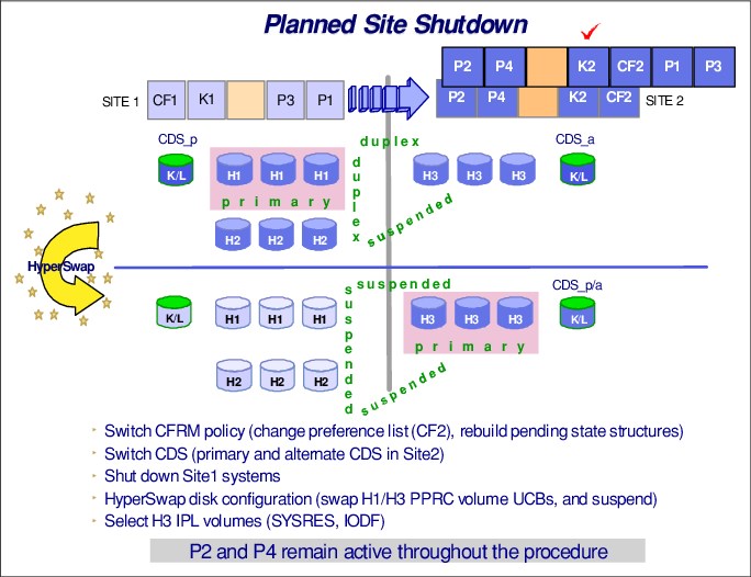
Figure 3-17 GDPS Metro Planned Action
In this example, a single action in GDPS executing a planned script of only a few lines results in a complete planned site switch. Specifically, the following actions are done by GDPS:
•The systems in Site1, P1 and P3, are stopped (P2 and P4 remain active in this example).
•The sysplex resources (CDS and CF) are switched to use only those in Site2.
•A HyperSwap is executed to use the disk in Site2 (RS3 disk). As a result of the swap GDPS automatically switches the IPL parameters (IPL address and load parameters) to reflect the new configuration.
•The IPL location for the P1 and P3 systems are changed to the backup LPAR location in Site2.
•The backup LPAR locations for P1 and P3 systems are activated.
•P1 and P3 are IPLed in Site2 using the disk in Site2.
Using GDPS removes the reliance on out-of-date documentation, provides a single repository for information about IPL addresses and load parameters, and ensures that the process is done the same way every time with no vital steps accidentally overlooked.
STP CTN role reassignments: Planned operations
GDPS provides a script statement that allows you to reconfigure an STP-only CTN by reassigning the STP-only CTN server roles. In an STP CTN servers (CPCs) are assigned special roles to identify which CPC is preferred to be the clock source (Preferred Time Server, or PTS), which CPC is able to take over as the clock source for planned and unplanned events (Backup Time Server, or BTS), which CPC is the active clock source (Current Time Server, or CTS), and which CPC assists in STP recovery (Arbiter).
It is strongly recommended that the server roles be reassigned before performing planned disruptive actions on any of these special role servers. Examples of planned disruptive actions are power-on reset (POR) and Activate/Deactivate. The script statement can be integrated as part of your existing control scripts to perform these planned disruptive actions.
For example, if you are planning to deactivate the CPC that is the PTS/CTS, you can now execute a script to perform the following tasks:
•Reassign the PTS/CTS role to a different CPC in the CTN
•Optionally also reassign the BTS and Arbiter roles if required
•Execute script statements you might already have in place today to deactivate the PTS/CTS CPC
After the disruptive action is completed you can execute a second script to restore the STP roles to their normal operational state, as listed here:
•Script statement to activate the CPC
•Reassign the STP server roles to their normal operational state
•Statements you might already have in existing scripts to perform IPLs and so on
Takeover scripts
Takeover scripts define actions that GDPS runs automatically after specific unplanned events occur. A reserved name is defined for each takeover script that correlates it to the specific unplanned event that it addresses. When one of the unplanned events occurs, GDPS Metro automatically runs the suitable takeover script if it was defined.
Two types of takeover scripts are available: post swap and CEC failure. The following sections provide more information about each type of script.
Post swap scripts
Post swap scripts define actions that GDPS runs after an unplanned HyperSwap. Several specific unplanned HyperSwap scenarios are available and for each one, a reserved name for the associated takeover script is used. In the case of an unplanned HyperSwap trigger, GDPS Metro immediately and automatically runs an unplanned HyperSwap. Following the HyperSwap operation, GDPS then runs the suitable takeover script if it was defined.
The post swap takeover scripts include reserved names that help GDPS determine the applicability of the script for the unplanned swap situation. For example, if an unplanned swap from RS1 to RS3 occurs, GDPS automatically schedules a script that is named SWAPSITE13 if you have defined it. Typical actions you might want to perform following an unplanned HyperSwap include resynchronizing mirroring for the MTIR replication leg in a dual-leg environment and changing the couple data set configuration.
For HyperSwap operations that swap production from one site to another, you might want to reconfigure STP to keep the CTS role on the CPC that is in the same site as the swapped-to, new primary devices.
CEC failure scripts
GDPS monitors data-related events and also performs system-related monitoring. When GDPS detects that a z/OS system is no longer active, it verifies whether the policy definition indicates that Auto IPL has been enabled, that the threshold of the number of IPLs in the predefined time window has not been exceeded, and that no planned action is active. If these conditions are met, GDPS can automatically re-IPL the system in place, bring it back into the Parallel Sysplex, and restart the application workload (see Figure 3-18).
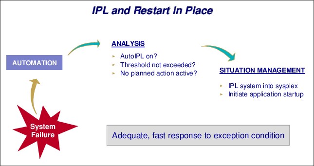
Figure 3-18 Recovering a failed image
Although Auto IPL processing occurs automatically based on policy and does not require a script, you can define CEC failure scripts to run specific actions other than re-IPLing in place when one or more systems fail as part of a complete CEC failure. In such a script, you might want to activate backup partitions on another CEC for all the systems on the failing CEC, activate CBU if suitable, and IPL these systems on the alternative CEC. You can have one such script defined in advance for every server in your configuration.
For example, if you have a CEC that is named CECA1, you can define a script that is named CECFAIL_CECA1. If GDPS Metro detects a complete failure of CECA1, GDPS Metro automatically runs the script that is named CECFAIL_CECA1 to handle the unplanned event.
Scripts for other unplanned events
The following sections describe other unplanned events for which you might want to define actions for GDPS Metro to run. In these cases, GDPS Metro does not automatically run the script after the event occurs. Rather, these scripts must be run from the panels or the GUI; therefore, they are considered control scripts.
STP CTN role reassignments: Unplanned failure
If a failure condition has resulted in the PTS, BTS, or Arbiter no longer being an operational synchronized CPC in the CTN, a suggestion is that after the failure and possible STP recovery action, the STP roles be reassigned to operational CPCs in the CTN. The reassignment reduces the potential for a sysplex outage in the event a second failure or planned action affects one of the remaining special role CPCs.
The script statement capability described in “STP CTN role reassignments: Planned operations” on page 99 can be used to integrate the STP role reassignment as part of an existing script and eliminate the requirement for the operator to perform the STP reconfiguration task manually at the HMC.
STP WTOR IEA394A response: Unplanned failure
As described in “Improved controlling system availability: Enhanced timer support” on page 70, a loss of synchronization with the sysplex timing source will generate a disabled console WTOR. This suspends all processing on the LPAR until a response to the WTOR is provided. The WTOR message is IEA394A if the CPC is in STP timing mode (either in an STP Mixed CTN or STP-only CTN).
GDPS, using scripts, can reply (either ABORT or RETRY) to the IEA394A sync WTOR for STP on systems that are spinning because of a loss of synchronization with their Current Time Source. As described in “Automated response to STP sync WTORs” on page 71, autonomic function exists to reply RETRY automatically for 60 minutes on any GDPS systems that have posted this WTOR.
The script statement complements and extends this function, as described:
•It provides the means to reply to the message after the 60-minute automatic reply window expires.
•It can reply to the WTOR on systems that are not GDPS systems (foreign systems) that are defined to GDPS; the autonomic function only replies on GDPS systems.
•It provides the ability to reply ABORT on any systems you do not want to restart for a given failure scenario before reconfiguration and synchronization of STP.
Batch scripts
GDPS also provides a flexible batch interface to invoke scripts from outside of GDPS. These scripts are known as batch scripts and can be started in the following ways:
•As a REXX program from a user terminal
•By using the IBM MVS MODIFY command to the NetView task
•From timers in NetView
•Triggered through the SA automation tables
This capability, along with the Query Services interface that is described in section 3.7.4, “Concurrent Copy cleanup” on page 107, provides a rich framework for user-customizable systems management procedures.
3.5.3 Application programming interfaces
GDPS provides two primary programming interfaces to allow other programs that are written by clients, Independent Software Vendors, and other IBM product areas to communicate with GDPS. These APIs allow clients, ISVs, and other IBM product areas to complement GDPS automation with their own automation code. The following sections describe the APIs provided by GDPS.
Query Services
GDPS maintains configuration information and status information in NetView variables for the various elements of the configuration that it manages. Query Services is a capability that allows NetView REXX programs to query the value for numerous GDPS internal variables. The variables that can be queried pertain to the Metro Mirror configuration, the system and sysplex resources that are managed by GDPS, and other GDPS facilities, such as HyperSwap and the GDPS Monitors.
In addition to the Query Services function that is part of the base GDPS product, GDPS provides several samples in the GDPS SAMPLIB library to demonstrate how Query Services can be used in client-written code.
GDPS also makes available to clients a sample tool called the Preserve Mirror Tool (PMT), which facilitates adding new disks to the GDPS Metro Mirror configuration and bringing these disks to duplex. The PMT tool, which is provided in source format, makes extensive use of GDPS Query Services and thereby provides clients with an excellent example of how to write programs to benefit from Query Services.
RESTful APIs
As described in “Query Services” on page 101, GDPS maintains configuration information and status information about the various elements of the configuration that it manages. Query Services can be used by REXX programs to query this information.
The GDPS RESTful API also provides the ability for programs to query this information. Because it is a RESTful API, it can be used by programs that are written in various programming languages, including REXX, that are running on various server platforms.
In addition to querying information about the GDPS environment, the GDPS RESTful API allows programs that are written by clients, ISVs, and other IBM product areas to start actions against various elements of the GDPS environment. Examples of these actions include starting and stopping Metro Mirror, IPLing and stopping systems, managing sysplex resources, and starting GDPS monitor processing. These capabilities enable clients, ISVs, and other IBM product areas provide an even richer set of functions to complement the GDPS functionality.
GDPS provides samples in the GDPS SAMPLIB library to demonstrate how the GDPS RESTful API can be used in programs.
3.5.4 Additional system management information
Most of the GDPS Standard Actions and several script commands require GDPS to communicate with the HMC. The interface GDPS uses to communicate with the HMC is called the BCP Internal Interface (BCPii). This interface allows GDPS to automate many of the HMC actions, such as Load, Stop (graceful shutdown), Reset, Activate LPAR, and Deactivate LPAR. GDPS can also perform ACTIVATE (power-on reset), CBU ACTIVATE/UNDO, OOCoD ACTIVATE/UNDO, and STP role reassignment actions against an HMC object that represents a CPC.
The GDPS LOAD and RESET Standard Actions (available through the GUI and NetView Standard Actions panels, the SYSPLEX script statement, and the RESTful APIs) allow specification of a CLEAR or NOCLEAR operand. This configuration provides operational flexibility to accommodate client procedures, which eliminates the requirement to use the HMC to perform specific LOAD and RESET actions.
Also, when you LOAD a system by using GDPS (by way of the GUI, NetView panels, scripts, or RESTful APIs), GDPS can listen for operator prompts from the system being IPLed and reply to such prompts. GDPS provides support for optionally replying to such IPL-time prompts automatically, removing reliance on operator skills and eliminating operator error for selected messages that require replies.
SYSRES Management
Today many clients maintain multiple alternate z/OS SYSRES devices (also known as IPLSETs) as part of their maintenance methodology. GDPS provides special support to allow clients to identify IPLSETs. This removes the requirement for clients to manage and maintain their own procedures when IPLing a system on a different alternate SYSRES device.
GDPS can automatically update the IPL pointers after any disk switch or disk recovery action that changes the GDPS primary disk location indicator for Metro Mirror disks. This removes the requirement for clients to perform additional script actions to switch IPL pointers after disk switches, and greatly simplifies operations for managing alternate SYSRES “sets.”
3.5.5 Securing the GDPS environment
GDPS uses RACF XFACILIT and GXFACILI resource classes to enable you to create a role-based security model for controlling access to the resources in your GDPS environment that is customized to your specific environment. Simple definitions can be used to control access at the panel option level or more granular definitions can be used to control access to specific types of resources, or even all the way down to the specific resource level.
With the role-based security model, you can create your own roles or you can use the common roles that GDPS recommends that include GDPS Administrator, GDPS Operator, GDPS User, and Non-GDPS User. You define the resources that these roles can access and the type of access they have to those resources by granting them access to the resource profiles that represent the various resources in your environment. Finally, you can grant access to various resources to users by adding them to the appropriate roles.
When you use the role-based security model, GDPS ensures that the user has sufficient authority to take a specific action against a specific resource, regardless of whether they are attempting to take the action by using the panels directly or by executing a GDPS script.
Finally, the GDPS Security Definition Utility tool is available to assist you with implementing your role-based security environment. For more information, see the GDPS Security Definition Utility guide.
3.6 GDPS Metro monitoring and alerting
The GDPS SDF panel, discussed in “Monitoring function: Status Display Facility” on page 91, is where GDPS dynamically displays color-coded alerts.
Alerts can be posted as a result of an unsolicited error situation that GDPS listens for. For example, if one of the multiple PPRC links that provide the path over which Metro Mirror operations take place is broken, there is an unsolicited error message issued. GDPS listens for this condition and will raise an alert on the SDF panel, notifying the operator of the fact that a PPRC link is not operational. Clients run with multiple PPRC links and if one is broken, Metro Mirror continues over any remaining links. However, it is important for operations to be aware that a link is broken and fix this situation because a reduced number of links results in reduced Metro Mirror bandwidth and reduced redundancy. If this problem is not fixed in a timely manner and more links fail, it can result in production impact because of insufficient mirroring bandwidth or total loss of Metro Mirror connectivity (which results in a freeze).
Alerts can also be posted as a result of GDPS periodically monitoring key resources and indicators that relate to the GDPS Metro environment. If any of these monitoring items are found to be in a state deemed to be not normal by GDPS, an alert is posted on SDF.
Various GDPS monitoring functions are executed on the GDPS controlling systems and on the production systems. This is because, from a software perspective, it is possible that different production systems have different views of some of the resources in the environment, and although status can be normal in one production system, it can be not normal in another. All GDPS alerts generated on one system in the GDPS sysplex are propagated to all other systems in the GDPS. This propagation of alerts provides for a single focal point of control. It is sufficient for the operator to monitor SDF on the master controlling system to be aware of all alerts generated in the entire GDPS complex.
When an alert is posted, the operator will have to investigate (or escalate, as appropriate) and corrective action will need to be taken for the reported problem as soon as possible. After the problem is corrected, this is detected during the next monitoring cycle and the alert is cleared by GDPS automatically.
GDPS Metro monitoring and alerting capability is intended to ensure that operations are notified of and can take corrective action for any problems in their environment that can affect the ability of GDPS Metro to do recovery operations. This will maximize the chance of achieving your availability and RPO/RTO commitments.
3.6.1 GDPS Metro health checks
In addition to the GDPS Metro monitoring described, GDPS provides health checks. These health checks are provided as a plug-in to the z/OS Health Checker infrastructure to check that certain settings related to GDPS adhere to preferred practices.
The z/OS Health Checker infrastructure is intended to check a variety of settings to determine whether these settings adhere to z/OS optimum values. For settings found to be not in line with preferred practices, exceptions are raised in the Spool Display and Search Facility (SDSF) and optionally, SDF alerts are also raised. If these settings do not adhere to recommendations, this issue can hamper the ability of GDPS to perform critical functions in a timely manner.
Often, if there are changes in the client environment, this might necessitate adjustment of various parameter settings associated with z/OS, GDPS, and other products. It is possible that you can miss making these adjustments, which can affect GDPS. The GDPS health checks are intended to detect such situations and avoid incidents where GDPS is unable to perform its job because of a setting that is perhaps less than ideal.
For example, GDPS Metro provides facilities for management of the couple data sets (CDS) for the GDPS sysplex. One of the health checks provided by GDPS Metro checks that the couple data sets are allocated and defined to GDPS in line with the GDPS preferred practices recommendations.
Similar to z/OS and other products that provide health checks, GDPS health checks are optional. Several optimum values that are checked and the frequency of the checks can be customized to cater to unique client environments and requirements.
There are a few z/OS preferred practices that conflict with GDPS preferred practices. The related z/OS and GDPS health checks result in conflicting exceptions being raised. For such health check items, to avoid conflicting exceptions, z/OS provides the ability to define a coexistence policy where you can indicate which practice is to take precedence; GDPS or z/OS. GDPS provides sample coexistence policy definitions for the GDPS checks that are known to be conflicting with z/OS.
GDPS also provides a convenient interface for managing the health checks using the GDPS panels (a similar interface is available using the GDPS GUI). You can use it to perform actions such as activate/deactivate or run any selected health check, view the customer overrides in effect for any optimum values, and so on.
Figure 3-19 shows a sample of the GDPS Health Checks Information Management panel. In this example, you see that all the health checks are enabled. The status of the last run is also shown, which indicates that some were successful and some resulted in raising a medium exception. The exceptions can also be viewed by using other options on the panel.
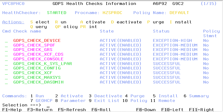
Figure 3-19 GDPS Metro Health Checks Information Management panel (VPC8PHC0)
3.7 Other facilities related to GDPS
Miscellaneous facilities that GDPS Metro provides can assist in various ways, such as reducing the window during which disaster recovery capability is not available.
3.7.1 HyperSwap coexistence
In the following sections we discuss the GDPS enhancements that remove some of the restrictions that had existed regarding HyperSwap coexistence with products such as Softek Transparent Data Migration Facility (TDMF) and IMS Extended Recovery Facility (XRF).
HyperSwap and TDMF coexistence
To minimize disruption to production workloads and service levels, many enterprises use TDMF for storage subsystem migrations and other disk relocation activities. The migration process is transparent to the application, and the data is continuously available for read and write activities throughout the migration process.
However, the HyperSwap function is mutually exclusive with software that moves volumes around by switching UCB pointers. The currently supported versions of TDMF and GDPS allow operational coexistence. With this support, TDMF automatically temporarily disables HyperSwap as part of the disk migration process only during the brief time when it switches UCB pointers.
Manual operator interaction is not required. Without this support, through operator intervention, HyperSwap is disabled for the entire disk migration, including the lengthy data copy phase.
HyperSwap and IMS XRF coexistence
HyperSwap also has a technical requirement that RESERVEs cannot be allowed in the hardware because the status cannot be reliably propagated by z/OS during the HyperSwap to the new primary volumes. For HyperSwap, all RESERVEs must be converted to GRS global enqueue through the GRS RNL lists.
IMS/XRF is a facility by which IMS can provide one active subsystem for transaction processing, and a backup subsystem that is ready to take over the workload. IMS/XRF issues hardware RESERVE commands during takeover processing and these cannot be converted to global enqueues through GRS RNL processing. This coexistence problem has also been resolved so that GDPS is informed before IMS issuing the hardware RESERVE, allowing it to automatically disable HyperSwap. After IMS has finished processing and releases the hardware RESERVE, GDPS is again informed and re-enables HyperSwap.
3.7.2 Reduced impact initial copy and resynchronization
Performing Metro Mirror copy of a large amount of data across a large number of devices while the same devices are used in production by application workloads can potentially affect production I/O service times if such copy operations are performed synchronously. Your disk subsystems and PPRC link capacity are typically sized for steady state update activity, but not for bulk, synchronous replication. Initial copying of disks and resynchronization of disks are examples of bulk copy operations that can affect production if performed synchronously.
There is no need to perform initial copy or resynchronizations using synchronous copy, because the secondary disks cannot be made consistent until all disks in the configuration have reached duplex state.
GDPS supports initial copy and resynchronization using asynchronous PPRC-XD (also known as Global Copy). When GDPS initiates copy operations in asynchronous copy mode, GDPS monitors progress of the copy operation and when the volumes are near full duplex state, GDPS converts the replication from the asynchronous copy mode to synchronous PPRC (Metro Mirror). Initial copy or resynchronization using PPRC-XD eliminates the performance impact of synchronous mirroring on production workloads.
Without asynchronous copy it might be necessary to defer these operations or reduce the number of volumes being copied at any given time. This would delay the mirror from reaching a duplex state, thus impacting a client’s ability to recovery. Use of the XD-mode asynchronous copy allows clients to establish or resynchronize mirroring during periods of high production workload, and can potentially reduce the time during which the configuration is exposed.
This function requires that all disk subsystems in the GDPS configuration support PPRC-XD.
3.7.3 Reserve Storage Pool
Reserve Storage Pool (RSP) is a type of resource introduced with the z/OS Management Facility (z/OSMF) that can simplify the management of defined but unused volumes. GDPS provides support for including RSP volumes in the Metro Mirror configuration that is managed by GDPS. Metro Mirror primary volumes are expected to be online in controlling systems, and GDPS monitoring on the GDPS controlling systems results in an alert being raised for any Metro Mirror primary device that is found to be offline. However, because z/OS does not allow RSP volumes to be brought online to any system, GDPS monitoring recognizes that an offline primary device is an RSP volume and suppresses alerting for these volumes.
3.7.4 Concurrent Copy cleanup
The DFSMS Concurrent Copy (CC) function uses a “sidefile” that is kept in the disk subsystem cache to maintain a copy of changed tracks that have not yet been copied. For a Metro Mirrored disk, this sidefile is not mirrored to the secondary subsystem. If a HyperSwap is executed while a Concurrent Copy operation is in progress, the application using Concurrent Copy will fail after the completion of the HyperSwap. GDPS will not allow a planned swap when a Concurrent Copy session exists against your primary Metro Mirror devices. However, unplanned swaps will still be allowed. Therefore, if you plan to use HyperSwap for primary disk subsystem failures (unplanned HyperSwap), try to eliminate any use of Concurrent Copy, because you cannot plan when a failure will occur.
Checking for CC is performed by GDPS immediately before performing a planned HyperSwap. SDF trace entries are generated if one or more CC sessions exist, and the swap command will end with no Metro Mirror device pairs being swapped. You must identify and terminate any CC against the Metro Mirror primary devices before the swap.
When attempting to resynchronize your disks, checking is performed to ensure that the secondary devices do not retain CC status from the time when they were primary devices. These are not supported as Metro Mirror secondary devices. Therefore, GDPS will not attempt to establish a duplex pair with secondary devices if it detects a CC session.
GDPS provides a function to discover and terminate Concurrent Copy sessions that would otherwise cause errors during a resync operation. The function is controlled by a keyword that provides options to disable, to conditionally enable, or to unconditionally enable the cleanup of Concurrent Copy sessions on the target disks. This capability eliminates the manual task of identifying and cleaning up orphaned Concurrent Copy sessions before resynchronizing a suspended Metro Mirror relationship.
3.7.5 Easy Tier Heat Map Transfer
IBM DS8000 Easy Tier optimizes data placement (placement of logical volumes) across the various physical tiers of storage within a disk subsystem to optimize application performance. The placement decisions are based on learning the data access patterns and can be changed dynamically and transparently to the applications using this data.
Metro Mirror replicates the data from the primary to the secondary disk subsystem; however, the Easy Tier learning information is not included in Metro Mirror scope. The secondary disk subsystems are optimized according to the workload on these subsystems, which is different than the activity on the primary (there is only write workload on the secondary whereas there is read/write activity on the primary). As a result of this difference, during a disk switch or disk recovery, the secondary disks that you switch to are likely to display different performance characteristics compared to the former primary.
Easy Tier Heat Map Transfer is the DS8000 capability to transfer the Easy Tier learning from a Metro Mirror primary to the secondary disk subsystems so that the secondary disk subsystems can also be optimized (based on this learning) and will have similar performance characteristics if it is promoted to become the primary.
GDPS integrates support for Heat Map Transfer. In a dual-leg configuration, Heat Map Transfer is established for both secondary targets. The appropriate Heat Map Transfer actions (such as start/stop of the processing and reversing transfer direction) are incorporated into the GDPS managed processes. For example, if Metro Mirror is temporarily suspended on a given leg by GDPS for a planned or unplanned secondary disk outage, Heat Map Transfer is also suspended on that leg, or if Metro Mirror direction is reversed as a result of a HyperSwap, Heat Map Transfer direction is also reversed.
3.8 Flexible testing, resync protection, and Logical Corruption Protection
Configuring point-in-time copy (FlashCopy or Safeguarded Copy) capacity in your GDPS Metro environment provides several significant benefits:
•You can conduct regular DR drills or other tests by using a copy of production data while production continues to run.
•You can save a consistent, “golden” copy of the Metro Mirror secondary data, which can be used if the primary disk or site is lost during a Metro Mirror resynchronization operation.
•You can save multiple consistent copies of all or a subset of the devices in your configuration, at different points in time, that can be used to recover from logical corruption events including cyber attacks and internal attacks.
FlashCopy and the various options related to FlashCopy are discussed in 2.6, “FlashCopy” on page 38. GDPS Metro supports taking a FlashCopy of the current primary or either of the current secondary disks sets. The COPY, NOCOPY, NOCOPY2COPY, and INCREMENTAL options are supported. CONSISTENT FlashCopy is supported in conjunction with COPY, NOCOPY, and INCREMENTAL FlashCopy.
FlashCopy can also be used, for example, to back up data without the need for extended outages to production systems; to provide data for data mining applications; for batch reporting, and so on.
GDPS Metro uses the FlashCopy technology and the Safeguarded Copy technology to provide a powerful solution for protecting against various flavors of logical data corruption, including cyber attacks and internal threats. This capability is referred to as Logical Corruption Protection (LCP). For more information about LCP, see Chapter 10, “GDPS Logical Corruption Protection and Testcopy Manager” on page 295.
3.8.1 Use of space-efficient FlashCopy volumes
As discussed in “Space-efficient FlashCopy (FlashCopy SE)” on page 40, by using space-efficient (SE) volumes, you might be able to lower the amount of physical storage needed and thereby reduce the cost associated with providing a tertiary copy of the data. GDPS provides support allowing space-efficient FlashCopy volumes to be used as FlashCopy target disk volumes. Whether a target device is space-efficient or not is transparent to GDPS; if any of the FlashCopy target devices defined to GDPS are space-efficient volumes, GDPS will simply use them. All GDPS FlashCopy operations, whether through GDPS scripts, the GUI, panels, or FlashCopies automatically taken by GDPS, can use space-efficient targets.
Space-efficient volumes are ideally suited for FlashCopy targets when used for resync protection. The FlashCopy is taken before the resync and can be withdrawn as soon as the resync operation is complete. As changed tracks are sent to the secondary for resync, the time zero (T0) copy of this data is moved from the secondary to the FlashCopy target device. This means that the total space requirement for the targets is equal to the number of tracks that were out of sync, which typically will be significantly less than a full set of fully provisioned disks.
Another potential use of space-efficient volumes is if you want to use the data for limited disaster recovery testing.
Understanding the characteristics of FlashCopy SE is important to determine whether this method of creating a point-in-time copy will satisfy your business requirements. For example, will it be acceptable to your business if, because of an unexpected workload condition, the extent pool on the disk subsystem for the space-efficient devices becomes full and your FlashCopy is invalidated so that you are unable to use it? If your business requirements dictate that the copy must always be guaranteed to be usable, space-efficient might not be the best option and you can consider using standard FlashCopy instead.
3.9 GDPS tools for GDPS Metro
GDPS Metro includes tools that provide function that is complementary to GDPS function. The tools represent the kind of function that all or many clients are likely to develop themselves to complement GDPS. The use of these tools eliminates the need for you to develop similar functions yourself. The tools are provided in source code format, which means that you can modify the code to suit your needs if the tool does not meet your requirements exactly.
The following tools are available with GDPS Metro:
•GDPS Console Interface Tool (also known as and referred to as GCI)
This tool facilitates the use of the MVS system console as an interface for submitting GDPS scripts for execution or running script commands.
•Preserve Mirror Tool (PMT)
This tool simplifies and automates the process of adding PPRC disk devices to a running GDPS environment. PMT is designed to minimize the time during which GDPS mirroring status is NOK, which maximizes the duration a duplex mirror (along with Freeze and HyperSwap capability) is preserved.
•GDPS XML Conversion (GeoXML) Tool
This tool helps you to convert a GDPS/PPRC GEOPARM configuration definition file for a single replication leg to GDPS Metro XML-format GEOPARM definitions. This process simplifies the task of defining the GDPS Metro configuration for GDPS/PPRC clients who are moving to the use of GDPS Metro.
•GDPS EasyLog Tool
This Microsoft Windows-based tool helps you to extract and easily download the MVS Syslog and NetView log from a z/OS environment. It also helps in analyzing the Netlog after it is downloaded to a workstation.
3.10 GDPS Metro co-operation with GDPS Continuous Availability
GDPS Metro provides facilities for co-operation with GDPS Continuous Availability if GDPS Continuous Availability is used to provide workload level protection for selected workloads that are running on the systems that are in the GDPS Metro sysplex.
See 7.5, “GDPS Continuous Availability co-operation with GDPS Metro” on page 238 for details.
See 7.5, “GDPS Continuous Availability co-operation with GDPS Metro” on page 238 for details.
3.11 Services component
As you have learned, GDPS provides much more than simply remote copy management. It also includes system, server hardware and sysplex management, automation, testing processes, disaster recovery processes, and so on.
Most installations do not have skills in all these areas readily available. It is also extremely rare to find a team that has this range of skills across many implementations. However, the GDPS Metro offering includes exactly that: access to a global team of specialists in all the disciplines you need to ensure a successful GDPS Metro implementation.
Specifically, the Services component includes several or all of the following services:
•Planning to determine availability requirements, configuration recommendations, and implementation and testing plans
•Installation and necessary customization of NetView and System Automation
•Remote copy implementation
•GDPS Metro automation code installation and policy customization
•Assistance in defining Recovery Point and Recovery Time objectives
•Education and training on GDPS Metro setup and operations
•Onsite implementation assistance
•Project management and support throughout the engagement
The sizing of the Services component of each project is tailored for that project, based on many factors including what automation is already in place, whether remote copy is already in place, whether the two centers are already in place with a multisite sysplex, and so on. This means that the skills provided are tailored to the specific needs of each particular implementation.
3.12 GDPS Metro prerequisites
For more information about the latest GDPS Metro prerequisites, see this web page.
3.13 Comparison of GDPS Metro versus other GDPS offerings
So many features and functions are available in the various members of the GDPS family that recalling them all and remembering which offerings support them is sometimes difficult. To position the offerings, Table 3-1 lists the key features and functions and indicates those features and functions that are delivered by the various GDPS offerings.
Table 3-1 Supported features matrix
|
Feature
|
GDPS Metro
|
GDPS HM
|
GDPS Virtual Appliance
|
GDPS XRC
|
GDPS GM
|
|
Continuous availability
|
Yes
|
Yes
|
Yes
|
No
|
No
|
|
Disaster recovery
|
Yes
|
Yes
|
Yes
|
Yes
|
Yes
|
|
CA/DR protection against multiple failures
|
Yes
|
No
|
No
|
No
|
No
|
|
Continuous Availability for foreign z/OS systems
|
Yes with z/OS proxy
|
No
|
No
|
No
|
No
|
|
Supported distance
|
200 km
300 km (BRS configuration)
|
200 km
300 km (BRS configuration)
|
200 km
300 km (BRS configuration)
|
Virtually unlimited
|
Virtually unlimited
|
|
Zero Suspend FlashCopy support
|
Yes, using CONSISTENT
|
Yes, using CONSISTENT for secondary only
|
No
|
Yes, using Zero Suspend FlashCopy
|
Yes, using CGPause
|
|
Reduced impact initial copy/resync
|
Yes
|
Yes
|
Yes
|
Not applicable
|
Not applicable
|
|
Tape replication support
|
Yes
|
No
|
No
|
No
|
No
|
|
Production sysplex automation
|
Yes
|
No
|
Not applicable
|
No
|
No
|
|
Span of control
|
Both sites
|
Both sites
(disk only)
|
Both sites
|
Recovery site
|
Disk at both sites; recovery site (CBU or LPARs)
|
|
GDPS scripting
|
Yes
|
No
|
Yes
|
Yes
|
Yes
|
|
Monitoring, alerting and health checks
|
Yes
|
Yes
|
Yes (except health checks)
|
Yes
|
Yes
|
|
Query Services
|
Yes
|
Yes
|
No
|
Yes
|
Yes
|
|
MSS support for added scalability
|
Yes (RS2 in MSS1, RS3 in MSS2)
|
Yes (secondary in MSS1)
|
No
|
No
|
Yes (GM FC and Primary for MGM in MSS1)
|
|
MGM 3-site and 4-site
|
Yes (all configurations)
|
Yes (3-site only and non-IR only)
|
No
|
Not applicable
|
Yes (all configurations)
|
|
MzGM
|
Yes
|
Yes
|
No
|
Yes
|
Not applicable
|
|
Fixed Block disk
|
Yes
|
Yes
|
No
|
No
|
Yes
|
|
z/OS equivalent function for Linux on IBM Z
|
Yes (Linux on IBM Z Systems running as a z/VM guest only)
|
No
|
Yes (Linux on IBM Z Systems running as a z/VM guest only)
|
Yes
|
Yes
|
|
GDPS GUI
|
Yes
|
Yes
|
Yes
|
No
|
Yes
|
3.14 Summary
GDPS Metro is a powerful offering that provides disaster recovery, continuous availability, and system/sysplex resource management capabilities. HyperSwap, available with GDPS Metro, provides the ability to transparently swap disks between disk locations. The power of automation allows you to test and perfect the actions to be taken, either for planned or unplanned changes, thus minimizing or eliminating the risk of human error.
This offering is one of the offerings in the GDPS family, along with GDPS Metro HyperSwap Manager, and GDPS Virtual Appliance, that offers the potential of zero data loss, and that can achieve the shortest recovery time objective, typically less than one hour following a complete site failure.
It is also one of the only members of the GDPS family, along with GDPS Virtual Appliance, that is based on hardware replication and provides the capability to manage the production LPARs. Although GDPS XRC and GDPS GM offer LPAR management, their scope for system management only includes the systems in the recovery site, and not the production systems running in Site1.
GDPS Metro, in a dual-leg configuration, is the only GDPS offering that can provide zero-data-loss disaster recovery protection, even after a primary disk failure.
In addition to the disaster recovery and planned reconfiguration capabilities, GDPS Metro also provides user-friendly interfaces for monitoring and managing the various elements of the GDPS configuration.
1 Only alternate subchannel set 1 (MSS1) is currently supported for defining the Metro Mirror secondary devices.
2 Only alternate subchannel set 1 (MSS1) is currently supported for defining the Metro Mirror secondary devices.
..................Content has been hidden....................
You can't read the all page of ebook, please click here login for view all page.