

GDPS Virtual Appliance
In this chapter, we provide an overview of the GDPS Virtual Appliance offering. The GDPS Virtual Appliance supports both planned and unplanned situations, which helps to maximize application availability and provide business continuity. In particular, a GDPS Virtual Appliance solution can deliver the following capabilities:
•Near-continuous availability solution
•Disaster recovery (DR) solution across metropolitan distances
•Recovery time objective (RTO) less than an hour
•Recovery point objective (RPO) of zero
The main objective of the GDPS Virtual Appliance is to provide these capabilities to clients using z/VM and Linux on IBM Z and do not have z/OS in their environments1. The virtual appliance model that are used by this offering results in a solution that is easily managed and operated without requiring z/OS skills.
The functions provided by the GDPS Virtual Appliance fall into two categories: protecting your data and controlling the resources managed by GDPS. These functions include the following:
•Protecting your data:
– Ensures the consistency of the secondary data if there is a disaster or suspected disaster, including the option to also ensure zero data loss
– Transparent switching to the secondary disk using HyperSwap
– Management of the remote copy configuration
•Controlling the resources managed by GDPS during normal operations, planned changes, and following a disaster:
– Monitoring and managing the state of the production Linux for IBM Z guest images and LPARs (shutdown, activating, deactivating, IPL, and automated recovery)
– Support for switching your disk, or systems, or both, to another site
– User-customizable scripts that control the GDPS Virtual Appliance action workflow for planned and unplanned outage scenarios
This chapter includes the following topics:
8.1 Introduction to the GDPS Virtual Appliance
The GDPS Virtual Appliance is a continuous availability and disaster recovery solution that handles many types of planned and unplanned outages. As mentioned in Chapter 1, “Introduction to business resilience and the role of GDPS” on page 1, most outages are planned, and even among unplanned outages, most are not disasters. The GDPS Virtual Appliance provides capabilities to help provide the required levels of availability across these outages and in a disaster scenario. This chapter describes the data integrity and availability protection as well as the systems management capabilities provided by the GDPS Virtual Appliance.
The term production system is used throughout this chapter to refer to any z/VM images together with the Linux on IBM Z guests that are being managed by this instance of the GDPS Virtual Appliance.
8.2 GDPS Virtual Appliance configuration components
This section contains a high-level description of the components in a GDPS Virtual Appliance configuration. The components consist of both hardware and software. The hardware includes the disk subsystems that contain the production data and the remote copy services that perform the data replication. The software components include GDPS and other automated management code that runs on the GDPS Virtual Appliance, and GDPS Multiplatform Resiliency for IBM Z (also known as xDR), which runs on the z/VM systems that are managed by the GDPS Virtual Appliance. Figure 8-1 shows an example of a GDPS Virtual Appliance environment.
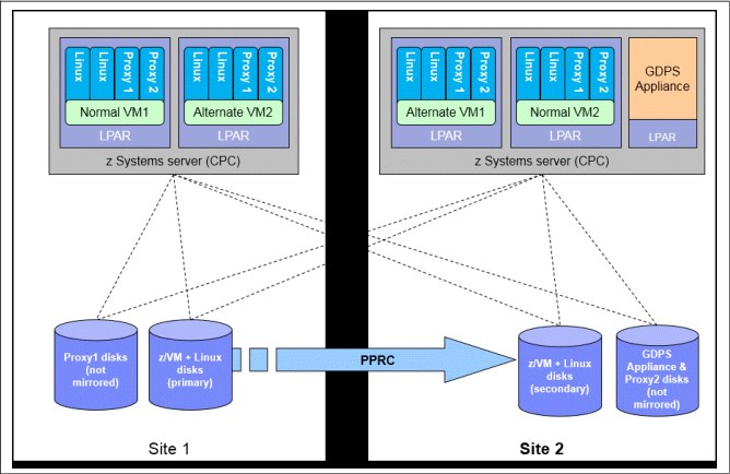
Figure 8-1 GDPS Virtual Appliance Environment
8.2.1 GDPS Virtual Appliance
The GDPS Virtual Appliance is a self-contained system that includes the GDPS Metro software that provides monitoring and management of Metro Mirror replication of production disk and monitoring and management of the z/VM systems that are using the production disk. The GDPS Appliance allows you to initiate planned events and to perform situation analysis after an unplanned event to determine the status of the production systems or the disks, and then to drive automated recovery actions. The GDPS Virtual Appliance is responsible for carrying out all actions during a planned event or following a disaster or potential disaster; actions such as managing the disk mirroring configuration, initiating a HyperSwap, initiating a freeze and implementing the freeze/swap policy actions, re-IPLing failed systems, and so on.
A GDPS Virtual Appliance environment is typically spread across two data centers (Site1 and Site2) where the primary copy of the production disk is normally in Site1. The GDPS Appliance must have connectivity to all the Site1 and Site2 primary and secondary devices that it will manage. For availability reasons, the GDPS Virtual Appliance runs in Site2 on local disk that is not mirrored with Metro Mirror. This provides failure isolation for the appliance system to ensure that it is not impacted by failures that affect the production systems and remains available to automate any recovery action.
8.2.2 Multiplatform Resiliency for IBM Z
The GDPS Virtual Appliance provides automated management of z/VM systems with a function called “Multiplatform Resiliency for IBM Z (also known as xDR)”. To provide these capabilities, the GDPS Virtual Appliance communicates and coordinates with System Automation for Multi-platforms (SA MP) running on Linux on IBM Z.
In each GDPS xDR-managed z/VM system, you must configure two special Linux guests, which are known as the proxy guests, as shown in Figure 8-1 on page 249. One proxy node is configured on Site1 disk and the other is configured on Site2 disk. The proxies are guests that are dedicated to providing communication and coordination with the GDPS Virtual Appliance They must run SA MP with the separately licensed xDR feature.
The proxy guests serve as the middleman for GDPS. They communicate commands from GDPS to z/VM, monitor the z/VM environment, and communicate status information and failure information (such as a HyperSwap triggers affecting the z/VM disk) back to the GDPS Virtual Appliance. At any time, the proxy node that is running on disk in the Metro Mirror secondary site is the Master proxy, and this is the proxy node with which the GDPS Virtual Appliance coordinates actions. The proxy node Master role is switched automatically when Metro Mirror disk is switched (or recovered) or when the Master proxy fails.
The disks being used by z/VM, the guest machines, and the proxy guest in this configuration must be CKD disks.
z/VM provides a HyperSwap function. With this capability, the virtual device associated with one real disk can be swapped transparently to another disk. GDPS coordinates planned and unplanned HyperSwap for z/VM disks, providing continuous data availability For site failures, GDPS provides a coordinated Freeze for data consistency across all z/VM systems.
GDPS can perform a graceful shutdown of z/VM and its guests and perform hardware actions such as LOAD and RESET against the z/VM system’s partition. GDPS supports taking a PSW restart dump of a z/VM system. Also, GDPS can manage CBU/OOCoD for IFLs and CPs on which z/VM systems are running.
8.3 Protecting data integrity and data availability with the GDPS Virtual Appliance
In 2.2, “Data consistency” on page 17, we point out that data integrity across primary and secondary volumes of data is essential to perform a database restart and accomplish an RTO of less than hour. This section provides details about how GDPS automation in the GDPS Virtual Appliance provides both data consistency if there are mirroring problems and data availability if there are disk problems.
The following types of disk problems trigger a GDPS automated reaction:
•Mirroring problems (Freeze triggers)
No problem exists writing to the primary disk subsystem, but a problem exists mirroring the data to the secondary disk subsystem. For more information, see 8.3.1, “GDPS Freeze function for mirroring failures” on page 251.”
•Primary disk problems (HyperSwap triggers)
There is a problem writing to the primary disk: Either a hard failure, or the disk subsystem is not accessible or not responsive. For more information, see 8.3.2, “GDPS HyperSwap function” on page 252.
8.3.1 GDPS Freeze function for mirroring failures
GDPS uses automation to stop all mirroring when a remote copy failure occurs. In particular, the GDPS automation uses the IBM PPRC Freeze/Run architecture, which is implemented as part of Metro Mirror on IBM disk subsystems and also by other enterprise disk vendors. In this way, if the disk hardware supports the Freeze/Run architecture, GDPS can ensure consistency across all data for the managed systems (consistency group) regardless of disk hardware type. This preferred approach differs from proprietary hardware approaches that work only for one type of disk hardware. For more information about data consistency with synchronous disk mirroring, see “Metro Mirror data consistency” on page 24.
When a mirroring failure occurs, this problem is classified as a Freeze trigger and GDPS stops activity across all disk subsystems at the time the initial failure is detected, thus ensuring that the dependent write consistency of the remote disks is maintained. This is what happens when a GDPS performs a Freeze:
•Remote copy is suspended for all device pairs in the configuration.
•While the suspend command is being processed, each device goes into a long busy state.
•No I/Os can be issued to the affected devices until the long busy state is thawed with the PPRC Run (or “thaw”) action or until it times out. The consistency group timer setting commonly defaults to 120 seconds, although for most configurations a longer or extended long busy (ELB) setting is preferred.
•All paths between the Metro Mirrored disks are removed, preventing further I/O to the secondary disks if Metro Mirror is accidentally restarted.
Because no I/Os are processed for a remote-copied volume during the ELB, dependent write logic ensures the consistency of the remote disks. GDPS performs a Freeze for all Metro Mirrored devices in the GDPS managed configuration.
|
Important: Because of the dependent write logic, it is not necessary for all devices to be frozen at the same instant. In a large configuration with many thousands of remote copy pairs, it is not unusual to see short gaps between the times when the Freeze command is issued to each disk subsystem. Because of the ELB, however, such gaps are not a problem.
|
After GDPS automation performs the Freeze and the consistency of the remote disks is protected, the GDPS Virtual Appliance will perform a Run action against all LSSs. This will remove the ELB and allow production systems to continue using these devices. The devices will be in remote copy-suspended mode, meaning that any further writes to these devices are no longer being mirrored. However, changes are being tracked by the hardware so that only the changed data will be resynchronized to the secondary disks later.
If the Freeze trigger turns out to be the first sign of an actual disaster, your z/VM systems might continue operating for an amount of time before those systems actually fail. Any updates made to the primary volumes during this time will not have been replicated to the secondary disk, and are therefore lost.
The GDPS Virtual Appliance uses a combination of storage subsystem and production system triggers to automatically secure, at the first indication of a potential disaster, a data-consistent secondary site copy of your data using the Freeze function. In this way, the secondary copy of the data is preserved in a consistent state, perhaps even before production applications are aware of any issues. Ensuring the data consistency of the secondary copy ensures that a normal system restart can be performed instead of having to perform DBMS forward recovery actions. This is an essential design element of GDPS to minimize the time to recover the critical workloads if there is a disaster at the primary site.
You can appreciate why such a process must be automated. When a device suspends, there is not enough time to launch a manual investigation process.
In summary, freeze is triggered as a result of a Metro Mirror suspension event for any primary disk in the GDPS Virtual Appliance configuration; that is, at the first sign that a duplex mirror that is going out of the duplex state. When a device suspends, all attached systems are sent a “State Change Interrupt” (SCI). A message is issued in all of those systems and then each VM system must issue multiple I/Os to investigate the reason for the suspension event.
When GDPS performs a freeze, all primary devices in the Metro Mirror configuration suspend. This can result in significant SCI traffic and many messages in all of the systems. With z/VM and microcode on the DS8000 disk subsystems, GDPS supports reporting suspensions in a summary message per LSS instead of at the individual device level. When compared to reporting suspensions on a per devices basis, the Summary Event Notification for PPRC Suspends (PPRCSUM) dramatically reduces the message traffic and extraneous processing associated with Metro Mirror suspension events and freeze processing.
8.3.2 GDPS HyperSwap function
If there is a problem writing or accessing the primary disk because of a failing, failed, or non-responsive primary disk, then there is a need to swap from the primary disks to the secondary disks.
The GDPS Virtual Appliance delivers a powerful function known as HyperSwap. HyperSwap provides the ability to swap from using the primary devices in a mirrored configuration to using what had been the secondary devices, transparent to the production systems and applications using these devices.
Without HyperSwap, a transparent disk swap is not possible. All systems using the primary disk would need to be shut down (or might have failed, depending on the nature and scope of the failure) and would have to be re-IPLed using the secondary disks. Disk failures are often a single point of failure for the entire production environment.
With HyperSwap, such a switch can be accomplished without IPL and with just a brief hold on application I/O. The HyperSwap function is completely controlled by automation, thus allowing all aspects of the disk configuration switch to be controlled through GDPS.
HyperSwap can be invoked in two ways:
•Planned HyperSwap
A planned HyperSwap is invoked by operator action using GDPS facilities. One example of a planned HyperSwap is where a HyperSwap is initiated in advance of planned disruptive maintenance to a disk subsystem.
•Unplanned HyperSwap
An unplanned HyperSwap is invoked automatically by GDPS, triggered by events that indicate the primary disk problem.
Primary disk problems can be detected as a direct result of an I/O operation to a specific device that fails because of a reason that indicates a primary disk problem such as:
– No paths available to the device
– Permanent error
– I/O timeout
In addition to a disk problem being detected as a result of an I/O operation, it is also possible for a primary disk subsystem to proactively report that it is experiencing an acute problem. The IBM DS8000 family has a special microcode function known as the Storage Controller Health Message Alert capability. Problems of different severity are reported by disk subsystems that support this capability. Those problems classified as acute are also treated as HyperSwap triggers. After systems are swapped to use the secondary disks, the disk subsystem and operating system can try to perform recovery actions on the former primary without impacting the applications using those disks.
Planned and unplanned HyperSwap have requirements in terms of the physical configuration, such as having it be symmetrically configured, and so on.
When a swap is initiated, GDPS always validates various conditions to ensure that it is safe to swap. For example, if the mirror is not fully duplex, that is, not all volume pairs are in a duplex state, a swap cannot be performed. The way that GDPS reacts to such conditions changes depending on the condition detected and whether the swap is a planned or unplanned swap.
Assuming that there are no show-stoppers and the swap proceeds, for both planned and unplanned HyperSwap, the systems that are using the primary volumes will experience a temporary pause in I/O processing. GDPS blocks I/O both at the channel subsystem level by performing a Freeze which results in all disks going into Extended Long Busy, and also in all systems, where I/O is quiesced at the operating system (UCB) level. This is to ensure that no systems use the disks until the switch is complete.
During the time when I/O is paused, the following process is completed:
1. The Metro Mirror configuration is physically switched. This includes physically changing the secondary disk status to primary. Secondary disks are protected and cannot be used by applications. Changing their status to primary allows them to come online to systems and be used.
2. The disks will be logically switched in each of the systems in the GDPS configuration. This involves switching the internal pointers in the operating system control blocks. After the switch, the operating system will point to the former secondary devices instead of the current primary devices.
3. For planned swaps, optionally, the mirroring direction can be reversed.
4. Finally, the systems resume operation using the new, swapped-to primary devices. The applications are not aware of the fact that different devices are now being used.
This brief pause during which systems are locked out of performing I/O is known as the User Impact Time.
The GDPS Virtual Appliance HyperSwaps all devices in the managed configuration. Just as the Freeze function applies to the entire consistency group, similarly HyperSwap is for the entire consistency group. For example, if a single mirrored volume fails and HyperSwap is invoked, processing is swapped to the secondary copy of all mirrored volumes for all managed systems in the configuration, including volumes in unaffected subsystems. This is because, to maintain disaster readiness, all primary volumes must be in the same site. If HyperSwap were to swap the only failed devices, you would then have several primaries in one site, and the remainder in the other site. This would also make for a significantly complex environment to operate and administer I/O configurations.
HyperSwap with less than full channel bandwidth
You may consider enabling unplanned HyperSwap even if you do not have sufficient cross-site channel bandwidth to sustain the full production workload for normal operations. Assuming that a disk failure is likely to cause an outage and you will need to switch to using disk in the other site, the unplanned HyperSwap might at least present you with the opportunity to perform an orderly shutdown of your systems first. Shutting down your systems cleanly avoids the complications and restart time elongation associated with a crash-restart of application subsystems.
8.3.3 GDPS use of DS8000 functions
GDPS strives to use (when it makes sense) enhancements to the IBM DS8000 disk technologies. In this section we provide information about the key DS8000 technologies that the GDPS Virtual Appliance supports and uses.
Metro Mirror Failover/Failback support
When a primary disk failure occurs and the disks are switched to the secondary devices, Metro Mirror Failover/Failback (FO/FB) support eliminates the need to do a full copy when reestablishing replication in the opposite direction. Because the primary and secondary volumes are often in the same state when the freeze occurred, the only differences between the volumes are the updates that occur to the secondary devices after the switch. Failover processing sets the secondary devices to primary suspended status and starts change recording for any subsequent changes made. When the mirror is reestablished with failback processing, the original primary devices become secondary devices and a resynchronization of changed tracks takes place.
The GDPS Virtual Appliance requires Metro Mirror FO/FB capability to be available on all disk subsystems in the managed configuration.
PPRC eXtended Distance (PPRC-XD)
PPRC-XD (also known as Global Copy) is an asynchronous form of the PPRC copy technology. GDPS uses PPRC-XD rather than synchronous PPRC (Metro Mirror) to reduce the performance impact of certain remote copy operations that potentially involve a large amount of data. For more information, see section 4.6.2, “GDPS HM reduced impact initial copy and resynchronization” on page 143.
Storage Controller Health Message Alert
This facilitates triggering an unplanned HyperSwap proactively when the disk subsystem reports an acute problem that requires extended recovery time. For more information about unplanned HyperSwap triggers, see 8.3.2, “GDPS HyperSwap function” on page 252.
PPRCS Summary Event Messages
GDPS supports the DS8000 PPRC Summary Event Messages (PPRCSUM) function, which is aimed at reducing the message traffic and the processing of these messages for Freeze events. For more information, see 8.3.1, “GDPS Freeze function for mirroring failures” on page 251.
Soft Fence
Soft Fence provides the capability to block access to selected devices. As discussed in 8.3.4, “Protecting secondary disks from accidental update” on page 256, GDPS uses Soft Fence to avoid write activity on disks that are exposed to accidental update in certain scenarios.
On-demand dump (also known as non-disruptive statesave)
When problems occur with disk subsystems such as those which result in an unplanned HyperSwap, a mirroring suspension or performance issues, a lack of diagnostic data from the time the event occurs can result in difficulties in identifying the root cause of the problem. Taking a full statesave can lead to temporary disruption to host I/O and is often frowned upon by clients for this reason. The on-demand dump (ODD) capability of the disk subsystem facilitates taking a non-disruptive statesave (NDSS) when such an event occurs. The microcode does this automatically for certain events, such as taking a dump of the primary disk subsystem that triggers a Metro Mirror freeze event. It also allows an NDSS to be requested. This enables first failure data capture (FFDC) and thus ensures that diagnostic data is available to aid problem determination. Be aware that not all information that is contained in a full statesave is contained in an NDSS and therefore there may still be failure situations where a full statesave is requested by the support organization.
GDPS provides support for taking an NDSS using the GDPS GUI. In addition to this support, GDPS autonomically takes an NDSS if there is an unplanned Freeze or HyperSwap event.
8.3.4 Protecting secondary disks from accidental update
A system cannot be IPLed by using a disk that is physically a Metro Mirror secondary disk because Metro Mirror secondary disks cannot be brought online to any systems. However, a disk can be secondary from a GDPS (and application use) perspective but physically have a simplex or primary status from a Metro Mirror perspective.
For both planned and unplanned HyperSwap, and a disk recovery, GDPS changes former secondary disks to primary or simplex state. However, these actions do not modify the state of the former primary devices, which remain in the primary state. Therefore, the former primary devices remain accessible and usable even though they are considered to be the secondary disks from a GDPS perspective. This makes it is possible to accidentally update or IPL from the wrong set of disks. Accidentally using the wrong set of disks can result in a potential data integrity or data loss problem.
The GDPS Virtual Appliance provides protection against using the wrong set of disks in the following ways:
•If you attempt to load a system through GDPS (either script or panel or GUI) using the wrong set of disks, GDPS rejects the load operation.
•GDPS uses a DS8000 disk subsystem capability, which is called Soft Fence for configurations where the disks support this function. Soft Fence provides the means to fence, which means block access to a selected device. GDPS uses Soft Fence when appropriate to fence devices that would otherwise be exposed to accidental update.
8.4 Managing the GDPS environment
You saw how the GDPS Virtual Appliance can protect your data during unplanned outages. However, as discussed in Chapter 1, “Introduction to business resilience and the role of GDPS” on page 1, most IBM Z outages are not disasters. Most are planned outages, with a small percentage of unplanned outages.
In this section, we describe other aspects of the GDPS Virtual Appliance, that is, its ability to monitor and manage the resources in its environment.
8.4.1 GDPS graphic user interface
The user interface that is used for managing the GDPS Virtual Appliance environment is known as the GDPS graphic user interface or GDPS GUI. Figure 8-2 shows the GDPS GUI home page.

Figure 8-2 GDPS GUI home page
As you can see, there are four distinct areas of the page:
1. Page Header
This area allows you to start the following GDPS actions on demand:
– Executing a GDPS monitoring process. For more information about GDPS monitors, see 8.5, “GDPS monitoring and alerting” on page 263.
– Temporarily disabling or reenabling HyperSwap.
2. Navigation menu
This area contains icon links to the other panels that are available. Clicking an icon link opens a new tab in the Main Window and displays the corresponding panel in the new tab, including the following examples:
– Dashboard: This panel is described in “Dashboard panel” on page 258.
– Standard Actions: This panel is described in “Standard Actions panel” on page 258.
– Planned Actions: This panel is described in “Planned Actions panel” on page 259.
– SDF Alerts: This panel is described in“SDF panel” on page 260.
3. Main Window
This area is a tabbed workspace where the various GDPS panels are displayed. The Dashboard panel is displayed by default and is described in “Dashboard panel” on page 258. Other tabs will be added to this area as additional panels are displayed. Inactive/hidden tabs can be brought to the foreground by clicking the associated tab.
4. Status Summary
This area contains a graphical summary of the status and health of the GDPS managed environment, including the HyperSwap status, the disk mirroring status, the number of alerts of each severity currently displayed on the appliance, and the number of outstanding operator replies currently displayed on the appliance.
Dashboard panel
The Dashboard panel is the anchor content for the main window. This panel tab is always available to be made active. It shows at a glance the status of the components in your GDPS environment. Figure 8-2 on page 257 shows an example of the Dashboard panel. It includes icons that can be selected for the processors and disk in both Site1 and Site2. It also graphically shows the current direction and the status of Metro Mirror, plus the percentage of volume pairs that are in duplex state.
Clicking the arrow indicating the status and direction of the mirror opens the LSS Pairs panel. This panel is described in “LSS Pairs panel” on page 261. Clicking the Site1 or Site2 processor icon opens the Standard Actions panel. This panel is described next.
Standard Actions panel
GDPS provides facilities to help manage many common system-related actions. There are two reasons to use the GDPS facilities to perform these Standard Actions:
•They are well tested and based on IBM recommended procedures.
•Using the GDPS interface lets GDPS know that the changes that it is seeing are planned changes, and therefore GDPS is not to react to these events.
Standard actions are performed using the Standard Actions panel, which is shown in Figure 8-3. This panel is displayed by clicking one of the processor icons that are displayed on the Dashboard panel (as described in “Dashboard panel” on page 258), or by clicking the Standard Actions icon on the navigation menu (as described in 8.4.1, “GDPS graphic user interface” on page 257).

Figure 8-3 GDPS GUI Standard Actions panel
The panel displays a list of all of the systems defined to GDPS. The upper portion of the panel contains site icons with a summary count of the number of systems up and down in each Site.
Above the system list header is a toolbar that allows you to perform actions such as stopping, loading, and resetting systems and activating and deactivating LPARs.
If you double-click a z/VM system in the list that is presented, another panel opens in which you can operate at the cluster or Linux on IBM Z guest level within that z/VM image.
Planned Actions panel
The Planned Actions panel (see Figure 8-4) is displayed by clicking the Planned Actions icon on the Navigation menu, as described in 8.4.1, “GDPS graphic user interface” on page 257.
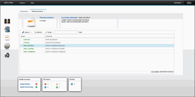
Figure 8-4 GDPS GUI Planned Actions panel
The panel displays a list of all of the Control scripts that have been defined to GDPS. A Control script is simply a procedure recognized by GDPS that pulls together one or more GDPS functions. Control scripts allow you to perform complex, multi-step operations without having to run each step individually by using various panel options. For more information about Control scripts, see section 8.4.2, “GDPS scripts” on page 262.
The upper portion of the Planned Actions panel contains a display box which contains the statements defined for any script that is selected. A script can be executed by double-clicking the script.
SDF panel
The SDF panel is the main panel for monitoring the status of GDPS managed resources. You navigate to this panel by clicking the SDF alert icon that is displayed on the Navigation menu, as described in 8.4.1, “GDPS graphic user interface” on page 257. An example of the SDF panel is shown in Figure 8-5.

Figure 8-5 GDPS GUI SDF panel
The panel is divided horizontally into two sections. The upper section contains icons that can be clicked for filtering the SDF entry list displayed in the lower section based on the type of alert. The filtering icon labels indicate how many alerts of that type and location in parenthesis.
Any SDF alerts that pass the applied filtering will be displayed in the SDF entry list at the bottom of the panel.
Above the entry list header is a toolbar that allows you to delete alerts, display help associated with alerts, and so on.
Remote Copy management panels
To manage the remote copy environment using the GDPS Virtual Appliance, you first define your entire remote copy configuration, including your primary and secondary LSSs, your primary and secondary devices, and your PPRC links, to GDPS in a file called the GEOPARM file. This enables GDPS to provide you with the capability to perform actions against all of the devices/pairs in your environment with a single action, rather than having to execute an action against each device/pair.
This section describes panel options provided by GDPS to enable you to manage your Remote Copy environment.
LSS Pairs panel
The initial panel for Remote Copy management is the LSS pairs panel. You navigate to this panel by clicking the mirroring status and direction arrow that is displayed on the Dashboard panel, as described in “Dashboard panel” on page 258. An example of the LSS Pairs panel is shown in Figure 8-6.

Figure 8-6 GDPS GUI LSS Pairs panel
The panel displays a list of all of the LSS pairs defined in the GDPS mirror. The upper left corner contains a summary count of the total number of LSS pairs and the number of LSS pairs by status severity. Double-clicking an LSS pair opens the Pairs panel for the LSS pair, as described in “Pairs panel” on page 262.
Above the LSS pair list header is a toolbar that enables you to perform various functions against all of the volume pairs in the selected LSS pairs. Examples of the functions you can perform using the toolbar include querying the status of the pairs, suspending mirroring for the pairs, restarting mirroring for the pairs, and recovering the secondary devices for the pairs.
Pairs panel
The Pair panel provides the ability to perform Remote Copy management at the volume pair level, rather than at the LSS pair level. An example of the Pairs panel is shown in Figure 8-7.
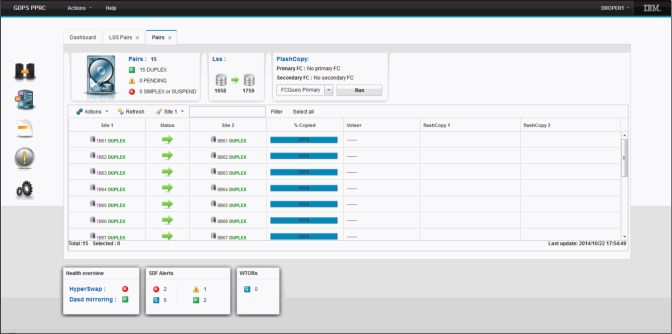
Figure 8-7 GDPS GUI Pairs panel
The panel displays a list of all of the volume pairs defined in the selected LSS. The upper left corner contains a summary count of the total number of volume pairs and the number of volume pairs by status severity. Double-clicking on a volume pair will issue a query for the pair and display the resulting output in a dialog box.
Above the volume pair list header is a toolbar that provides you the ability to perform various functions against all of the selected volume pairs. Examples include querying the status of the pairs, suspending mirroring for the pairs, restarting mirroring for the pairs, and recovering the secondary devices for the pairs.
8.4.2 GDPS scripts
As previously mentioned, GDPS provides the ability for you to automate complex, multi-step planned operations against your Remote Copy environment and against the production systems in your environment through the use of Control scripts.
Again, a script is a procedure recognized by GDPS that pulls together one or more GDPS functions. When executing a script, GDPS performs the first statement in the list, checks the result, and only if it is successful, proceeds to the next statement. If you perform the same steps manually, you would have to check results, which can be time-consuming, and then initiate the next action. With scripts, the process is automated.
Scripts are powerful because they can access the full capability of GDPS. The ability to invoke GDPS functions through a script provides the following benefits:
•Speed
The script will execute the requested actions and check results at machine speeds. Unlike a human, it does not need to search for the latest procedures or the commands manual.
•Consistency
With automation, your procedures will execute in exactly the same way, time after time.
•Thoroughly tested procedures
Because they behave in a consistent manner, you can test your procedures over and over until you are sure they do everything that you want, in exactly the manner that you want. Also, because you need to code everything and cannot assume a level of knowledge (as you might with instructions intended for a human), you are forced to thoroughly think out every aspect of the action the script is intended to undertake. And because of the repeatability and ease of use of the scripts, they lend themselves more easily to frequent testing than manual procedures.
8.4.3 System Management actions
Most of the GDPS Standard Actions require actions to be done on the HMC. The interface between the GDPS Virtual Appliance and the HMC is through a facility called the BCP Internal Interface (BCPii), and this allows GDPS to communicate directly with the hardware for automation of HMC actions such as LOAD, RESET, Activate LPAR, and Deactivate LPAR. GDPS can also perform ACTIVATE (power-on reset), CBU ACTIVATE/UNDO, and OOCoD ACTIVATE/UNDO.
Furthermore, when you LOAD a z/VM system using GDPS (panels or scripts), GDPS will listen for certain2 operator prompts from the system being IPLed and reply to the prompts. This support for replying to these IPL-time prompts automatically, helps to remove reliance on operator skills and eliminating operator error for any messages that require replies.
SYSRES Management
Today many clients maintain multiple alternate z/VM SYSRES devices (also known as IPLSETs) as part of their maintenance methodology. GDPS provides special support to allow clients to identify IPLSETs. This removes the requirement for clients to manage and maintain their own procedures when IPLing a system on a different alternate SYSRES device.
GDPS can automatically update the IPL pointers after any disk switch or disk recovery action that changes the GDPS primary site indicator for Metro Mirror disks. This removes the requirement for clients to perform additional script actions to switch IPL pointers after disk switches, and greatly simplifies operations for managing alternate SYSRES “sets.”
8.5 GDPS monitoring and alerting
As discussed in “SDF panel” on page 260, the GDPS SDF panel is where GDPS dynamically displays color-coded alerts.
Alerts can be posted as a result of an unsolicited error situation for which GDPS listens. For example, if one of the multiple PPRC links that provide the path over which Metro Mirror operations take place is broken, an unsolicited error message is issued.
GDPS listens for this condition and raises an alert on the SDF panel, which notifies the operator of the fact that a PPRC link is not operational. Clients run with multiple PPRC links and if one is broken, Metro Mirror continues over any remaining links.
However, it is important for operations to be aware that a link is broken and fix this situation because a reduced number of links results in reduced Metro Mirror bandwidth and reduced redundancy. If this problem is not fixed in a timely manner and more links fail, it can result in production impact because of insufficient mirroring bandwidth or total loss of Metro Mirror connectivity (which results in a freeze).
Alerts can also be posted as a result of GDPS periodically monitoring key resources and indicators that relate to the GDPS Virtual Appliance environment. If any of these monitoring items are found to be in a state deemed to be not normal by GDPS, an alert is posted which can be viewed using the GDPS GUI on the appliance system.
When an alert is posted, the operator will have to investigate (or escalate, as appropriate) and corrective action will need to be taken for the reported problem as soon as possible. After the problem is corrected, this is detected during the next monitoring cycle and the alert is cleared by GDPS automatically.
The GDPS Virtual Appliance monitoring and alerting capability is intended to ensure that operations are notified of and can take corrective action for any problems in their environment that can affect the ability of the appliance to do recovery operations. This maximizes the chance of achieving your availability and RPO and RTO commitments.
8.6 Services component
As you have learned, GDPS touches on much more than simply remote copy. It also includes automation, database management and recovery, testing processes, disaster recovery processes, and other areas.
Most installations do not have skills in all these areas readily available. It is extremely rare to find a team that has this range of skills across many implementations. However, the GDPS Virtual Appliance offering includes exactly that: Access to a global team of specialists in all the disciplines you need to ensure a successful GDPS Virtual Appliance implementation.
Specifically, the Services component includes several or all of the following services:
•Planning to determine availability requirements, configuration recommendations, and implementation and testing plans
•Remote copy implementation
•GDPS Virtual Appliance installation and policy customization
•Assistance in defining Recovery Point and Recovery Time objectives
•Education and training on the GDPS Virtual Appliance setup and operations
•Onsite implementation assistance
•Project management and support throughout the engagement
The sizing of the Services component of each project is tailored for that project, based on many factors including what automation is already in place, whether remote copy is already in place, the cross-site connectivity in place, and so on. This means that the skills provided are tailored to the specific needs of each particular implementation.
8.7 GDPS Virtual Appliance prerequisites
For more information about GDPS Virtual Appliance prerequisites, see this website.
8.8 GDPS Virtual Appliance compared to other GDPS offerings
So many features and functions are available in the various members of the GDPS family that recalling them all and remembering which offerings support them is sometimes difficult. To position the offerings, Table 8-1 lists the key features and functions and indicates which ones are delivered by the various GDPS offerings.
Table 8-1 Supported features matrix
|
Feature
|
GDPS Metro
|
GDPS HM
|
GDPS Virtual Appliance
|
GDPS XRC
|
GDPS GM
|
|
Continuous availability
|
Yes
|
Yes
|
Yes
|
No
|
No
|
|
Disaster recovery
|
Yes
|
Yes
|
Yes
|
Yes
|
Yes
|
|
CA/DR protection against multiple failures
|
Yes
|
No
|
No
|
No
|
No
|
|
Continuous Availability for foreign z/OS systems
|
Yes with z/OS proxy
|
No
|
No
|
No
|
No
|
|
Supported distance
|
200 km
300 km (BRS configuration)
|
200 km
300 km (BRS configuration)
|
200 km
300 km (BRS configuration)
|
Virtually unlimited
|
Virtually unlimited
|
|
Zero Suspend FlashCopy support
|
Yes, using CONSISTENT
|
Yes, using CONSISTENT for secondary only
|
No
|
Yes, using Zero Suspend FlashCopy
|
Yes, using CGPause
|
|
Reduced impact initial copy/resync
|
Yes
|
Yes
|
Yes
|
Not applicable
|
Not applicable
|
|
Tape replication support
|
Yes
|
No
|
No
|
No
|
No
|
|
Production sysplex automation
|
Yes
|
No
|
Not applicable
|
No
|
No
|
|
Span of control
|
Both sites
|
Both sites
(disk only)
|
Both sites
|
Recovery site
|
Disk at both sites; recovery site (CBU or LPARs)
|
|
GDPS scripting
|
Yes
|
No
|
Yes
|
Yes
|
Yes
|
|
Monitoring, alerting and health checks
|
Yes
|
Yes
|
Yes (except health checks)
|
Yes
|
Yes
|
|
Query Services
|
Yes
|
Yes
|
No
|
Yes
|
Yes
|
|
MSS support for added scalability
|
Yes (RS2 in MSS1, RS3 in MSS2)
|
Yes (secondary in MSS1)
|
No
|
No
|
Yes (GM FC and Primary for MGM in MSS1)
|
|
MGM 3-site and 4-site
|
Yes (all configurations)
|
Yes (3-site only and non-IR only)
|
No
|
Not applicable
|
Yes (all configurations)
|
|
MzGM
|
Yes
|
Yes
|
No
|
Yes
|
Not applicable
|
|
Fixed Block disk
|
Yes
|
Yes
|
No
|
No
|
Yes
|
|
z/OS equivalent function for Linux on IBM Z
|
Yes (Linux on IBM Z Systems running as a z/VM guest only)
|
No
|
Yes (Linux on IBM Z Systems running as a z/VM guest only)
|
Yes
|
Yes
|
|
GDPS GUI
|
Yes
|
Yes
|
Yes
|
No
|
Yes
|
8.9 Summary
The GDPS Virtual Appliance is a powerful offering that provides disaster recovery, continuous availability, and system resource management capabilities for z/VM and Linux on IBM Z. GDPS Appliance is the only GDPS offering that is packaged in a virtual appliance, eliminating the necessity for z/OS and sysplex skills in order to manage and operate the solution.
HyperSwap, available with the GDPS Virtual Appliance, provides the ability to transparently swap disks between two sites. The power of automation allows you to test and perfect the actions to be taken, either for planned or unplanned changes, thus minimizing or eliminating the risk of human error.
This is one of the offerings in the GDPS family, along with GDPS HMHM and GDPS Metro, that offers the potential of zero data loss, and that can achieve the shortest recovery time objective, typically less than one hour following a complete site failure.
It is also one of the only members of the GDPS family, again along with GDPS Metro, that is based on hardware replication and that provides the capability to manage the production LPARs. Although GDPS XRC and GDPS GM offer LPAR management, their scope for system management is limited, and only includes the systems in the recovery site, and not the production systems running in Site1.
In addition to the disaster recovery and planned reconfiguration capabilities, the GDPS Virtual Appliance also provides a user-friendly interface for monitoring and managing the various elements of the GDPS configuration.
1 For clients who run z/OS and have z/OS skills, equivalent capabilities exist by using the GDPS Metro Multiplatform Resiliency for IBM Z as described in “Multiplatform Resiliency for z/VM” on page 79.
2 Only operator prompts that can be safely replied to in a consistent manner are candidates for automatic replies.
..................Content has been hidden....................
You can't read the all page of ebook, please click here login for view all page.