
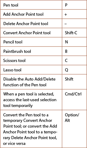
12. Reshape

In This Chapter
Reshaping objects with the Pencil or Paintbrush tool
Applying a variable width profile preset to an object’s stroke
Changing an object’s stroke width using the Width tool
Reshaping objects with the Blob Brush tool
EXERCISE: Draw and reshape objects in a freehand style
EXERCISE: Create a brush with the Reshape tool
Reshaping objects using commands
EXERCISE: Draw a glass of beer
In Chapters 6 and 7 you learned how to draw paths without needing to think about their individual components. In this important chapter, you’ll learn how to reshape a path’s contour by manipulating the nuts and bolts that all paths are composed of: direction handles, anchor points, and segments. Once you learn how to change the position, number, or type (smooth or corner) of anchor points on a path, you’ll be able to create just about any shape imaginable.
Other techniques covered in this chapter include learning how to quickly reshape all or part of a path with the Pencil, Anchor Point, Paintbrush, Blob Brush, Path Eraser, Eraser, and Reshape tools; change the profile and width of a stroke; align anchor points; join endpoints; reshape objects via an Effect command; combine paths; and split and cut paths. This chapter also includes three practice exercises.
The building blocks of a path
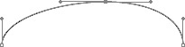
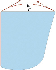
In Illustrator, all paths are composed of straight and/or curved segments that are connected by anchor points. A path can be open, with two endpoints, or closed, with no endpoints. Smooth anchor points have a pair of direction handles that move in tandem, whereas corner anchor points have no direction handles, one direction handle, or a pair of direction handles that move independently.A By dragging the end of a direction handle, you can change the shape of the curve it’s connected to. The angle of a direction handle controls the slope of the curve that leads into the anchor point; the length of a direction handle controls the height of the curve.
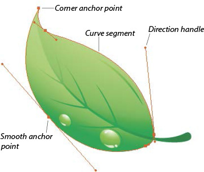
A You can manipulate the basic components of a path manually by dragging, or by using a tool or command.
Moving points and segments
If you move an anchor point, the segments that are connected to it reshape, lengthen, or shorten accordingly. If you move a straight segment, the anchor points it’s connected to move with it, whereas if you move a curve segment, the curve reshapes but the connecting anchor points remain stationary.
Note: For the instructions in this chapter, make sure Highlight Anchors on Mouse Over is checked in Illustrator/Edit > Preferences > Selection & Anchor Display. And while that dialog is open, you can also choose preferences for the display of anchor points and handles (see page 411).
To move an anchor point or a segment:
1. Choose the Direct Selection tool ![]() (A), and click a blank area of the document to deselect.
(A), and click a blank area of the document to deselect.
2. Move the pointer over the edge of an object, and do any of the following: Drag an anchor point (it will enlarge when the pointer is over it);A drag a segment (it will reshape the segment);B or click an anchor point or segment, then press an arrow key. For the first two methods, you can use the alignment guides feature of Smart Guides for precise positioning.
A We moved an anchor point, with the help of Smart Guides for positioning.

B We moved a segment.
![]() Shift-drag a point or segment to constrain the movement to a multiple of 45°.
Shift-drag a point or segment to constrain the movement to a multiple of 45°.
![]() You can move more than one point or segment at a time, even if they’re on different paths. To select them first, Shift-click them individually or drag a marquee around them.
You can move more than one point or segment at a time, even if they’re on different paths. To select them first, Shift-click them individually or drag a marquee around them.
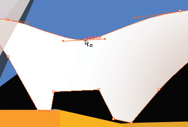
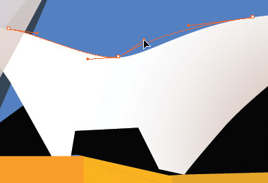
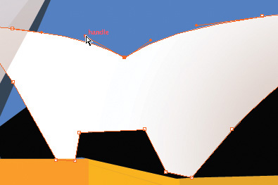
Reshaping curves
In the instructions above, you learned that you can drag an anchor point or a curve segment to reshape a curve. Another — and more precise — way to reshape a curve is to lengthen, shorten, or change the angle of the direction handles on a curve point.
To reshape a curve segment:
1. Choose the Direct Selection tool ![]() (A).
(A).
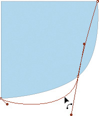
2. Click an anchor point or a curve segment.C
C We selected an anchor point on a shape.
3. Do either of the following:
Drag the end of a direction handle toward or away from the anchor point.D
D We dragged the end of a direction handle away from the anchor point, to reshape the curve.
Rotate the end of a direction handle around the anchor point. You can use Shift to constrain the angle of the handle, or position the handle using the alignment guides feature of Smart Guides.
Converting points
Corner anchor points either have no direction handles, or have direction handles that move independently of each other. The pair of direction handles on a smooth point always stay in a straight line and rotate in tandem (although they can be different lengths). With a click of a button, you can convert any corner point to a smooth point.
To convert a corner anchor point to a smooth anchor point:
1. In Illustrator/Edit > Preferences > Selection & Anchor Display, make sure Highlight Anchors on Mouse Over is checked. Click OK.
2. Choose the Direct Selection tool ![]() (A), and deselect.
(A), and deselect.
3. Pass the pointer over a corner anchor point on a path, and when a point becomes highlighted (enlarged), click to select it.A
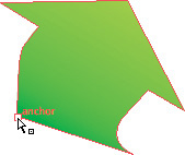
A To convert a corner point to a smooth one, click it with the Direct Selection tool ...
4. On the Control panel, click the Convert Selected Anchor Points to Smooth button.![]() B–C Direction handles will appear on the selected point, and the segments that are connected to it will become curved.
B–C Direction handles will appear on the selected point, and the segments that are connected to it will become curved.
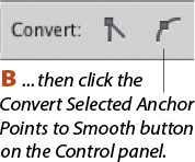
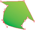
C Direction handles appear for the selected anchor point.
5. Optional: To reshape the curve, with the Direct Selection tool, drag either one of the direction handles.D
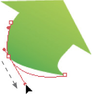
D You can drag either direction handle to modify the curve.
![]() You can also convert a corner point to a smooth point by using the Convert Anchor Point tool (Shift-C). Move the pointer over a corner point, and when it becomes highlighted, drag away from it. Direction handles will appear as you drag.
You can also convert a corner point to a smooth point by using the Convert Anchor Point tool (Shift-C). Move the pointer over a corner point, and when it becomes highlighted, drag away from it. Direction handles will appear as you drag.
![]() To learn more about converting points, see pages 303–305.
To learn more about converting points, see pages 303–305.
![]() To round the corners on a selected path by using an editable and removable effect, use the Effect > (Illustrator Effects) Stylize > Round Corners command.E–F Once you have applied the effect, you can click the effect listing on the Appearance panel to reopen the Round Corners dialog at any time, and change the Radius value. See page 206. (To straighten out the rounded corners, delete the effect listing from the Appearance panel.)
To round the corners on a selected path by using an editable and removable effect, use the Effect > (Illustrator Effects) Stylize > Round Corners command.E–F Once you have applied the effect, you can click the effect listing on the Appearance panel to reopen the Round Corners dialog at any time, and change the Radius value. See page 206. (To straighten out the rounded corners, delete the effect listing from the Appearance panel.)
E All the objects in this original artwork have sharp corners.
F The Effect > Stylize > Round Corners command rounded all the corners.
Creating a Tearoff Toolbar
To practice the techniques in this chapter, we recommend tearing off the toolbar for the Pen tool so the Pen and its cohorts are easily accessible. (Once you memorize the shortcuts for accessing these tools, you won’t need to display the toolbar.)
To convert a smooth anchor point to a corner anchor point:
1. Choose the Direct Selection tool ![]() (A), and deselect.
(A), and deselect.
2. Pass the pointer over a smooth anchor point on a path, and when it becomes highlighted, click it.A

A Click a smooth anchor point, then click the Convert Selected Anchor Points to Corner button on the Control panel.
3. On the Control panel, click the Convert Selected Anchor Points to Corner button.![]() B The direction handles will disappear from the anchor point.
B The direction handles will disappear from the anchor point.
B The smooth point is converted to a corner point.
![]() You can also convert a smooth point to a corner point (or vice versa) by clicking it with the Convert Anchor Point tool
You can also convert a smooth point to a corner point (or vice versa) by clicking it with the Convert Anchor Point tool ![]() (Shift-C).
(Shift-C).
In these steps, you will convert direction handles that stay in a straight line into handles that can be rotated independently of each other.
To rotate direction handles independently:
1. Choose the Direct Selection tool ![]() (A).
(A).
2. Deselect, click the edge of an object to display its anchor points, then click a smooth point.C
C We selected a smooth point on an object.
3. Choose the Convert Anchor Point tool ![]() (Shift-C).
(Shift-C).
4. Drag one of the direction handles on the point. The curve segment it is connected to will reshape as you drag.D
D We moved one direction handle with the Convert Anchor Point tool.
5. Choose the Direct Selection tool again (A), click the anchor point, then drag the other direction handle for the same anchor point.E
E We moved the second direction handle.
![]() To restore a corner point with direction handles that rotate independently to a smooth point, follow the steps on the preceding page.
To restore a corner point with direction handles that rotate independently to a smooth point, follow the steps on the preceding page.
![]() When the Pen tool
When the Pen tool ![]() (P) is selected, you can hold down Option/Alt to turn it into a temporary Convert Anchor Point tool.
(P) is selected, you can hold down Option/Alt to turn it into a temporary Convert Anchor Point tool.
![]() To select all the direction handles on one or more selected objects, from the Select > Object submenu, choose Direction Handles.
To select all the direction handles on one or more selected objects, from the Select > Object submenu, choose Direction Handles.
To add anchor points to a path manually:
1. Choose the Selection tool ![]() (V), then select or isolate an object.
(V), then select or isolate an object.
2. Do either of the following:
Choose the Add Anchor Point tool ![]() (+).
(+).
Choose the Pen tool ![]() (P), and make sure Disable Auto Add/Delete is unchecked in Illustrator/Edit > Preferences > General (yes, it’s a confusing double negative).
(P), and make sure Disable Auto Add/Delete is unchecked in Illustrator/Edit > Preferences > General (yes, it’s a confusing double negative).
3. Click the edge of the object. A new, selected anchor point appears.A Repeat to add more points to the path, if desired.
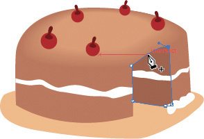
A We clicked a segment to add a new point.
![]() To locate the edge of a path, make sure Object Highlighting is checked in Illustrator/Edit > Preferences > Smart Guides, and turn on the Smart Guides feature (Cmd-U/Ctrl-U). As you move the pointer over the edge of an object, the path outline will appear as a Smart Guide.
To locate the edge of a path, make sure Object Highlighting is checked in Illustrator/Edit > Preferences > Smart Guides, and turn on the Smart Guides feature (Cmd-U/Ctrl-U). As you move the pointer over the edge of an object, the path outline will appear as a Smart Guide.
Logically, an anchor point that you add to a curve segment will be a smooth point with direction handles, whereas an anchor point that you add to a straight segment will be a corner point with no direction handles.
4. Optional: With the Direct Selection tool (A), move the new anchor point.B If it’s a smooth point, you can also lengthen or rotate its direction handles.
B Then we moved the new point.
![]() If you don’t click precisely on a segment with the Add Anchor Point tool, an alert dialog may appear. Click OK, then try again.
If you don’t click precisely on a segment with the Add Anchor Point tool, an alert dialog may appear. Click OK, then try again.
![]() Hold down Option/Alt to turn the Add Anchor Point tool into a temporary Delete Anchor Point tool, or vice versa.
Hold down Option/Alt to turn the Add Anchor Point tool into a temporary Delete Anchor Point tool, or vice versa.
Getting a Good Curve
By paying attention to the placement of points, you can produce smoother curves. When reshaping paths (and while drawing them, as you will see in Chapter 21), place points at the ends of a curve instead of at the middle.
It’s hard to draw a symmetrical curve if you place a point at the high point.
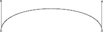
For a more symmetrical curve, place points only at the ends.
The Add Anchor Points command inserts one point between each pair of existing anchor points in a selected object.
To add anchor points to a path via a command:
1. Choose the Selection tool ![]() (V), then select the object(s) to which points are to be added.
(V), then select the object(s) to which points are to be added.
2. Choose Object > Path > Add Anchor Points.A–C If desired, repeat to add yet more points.
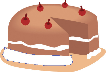
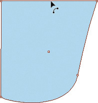
A We added this simple white object to this artwork.
B We applied the Add Anchor Points command to the object.

C We applied Effect > Distort & Transform > Roughen to alter the shape. Because points were added to the path, we were able to keep the Roughen settings low, which produced less overall distortion.
Putting an Object into Isolation Mode
Switch to the Selection tool quickly by pressing V, then double-click an object or group to isolate it.
Selecting Tools for Reshaping Paths
Want to become a speed demon in Illustrator? Learn some of these shortcuts.
You can add segments to a path with the Pencil tool, regardless of which tool was used to draw the path, and whether or not the path has an applied brush stroke. If a path does have a brush stroke, you can also add to it by using the Paintbrush tool.
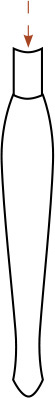
To add to an open path with the Pencil or Paintbrush tool:
1. Choose the Selection tool ![]() (V), then select or isolate an open path.
(V), then select or isolate an open path.
2. Double-click the Pencil tool ![]() (N) to open the options dialog for that tool. Or if the path has a brush stroke, you can double-click the Paintbrush tool
(N) to open the options dialog for that tool. Or if the path has a brush stroke, you can double-click the Paintbrush tool ![]() instead.
instead.
3. In the tool preferences dialog, make sure Edit Selected Paths is checked, then click OK.
4. Position the pointer directly over the path, then draw an addition to the path.A–B
A We positioned the Paintbrush pointer over a path.

B We drew an addition to the path.
![]() If you end up with a new, separate path instead of an addition to an existing path, delete the new one. On your next try, make sure the pointer is directly over the path before you begin drawing. Or when using the Paintbrush tool, verify that the path to which you’re adding a segment has a brush stroke.
If you end up with a new, separate path instead of an addition to an existing path, delete the new one. On your next try, make sure the pointer is directly over the path before you begin drawing. Or when using the Paintbrush tool, verify that the path to which you’re adding a segment has a brush stroke.
To add to an open path with the Pen tool:
1. Choose the Pen tool ![]() (P).
(P).
2. Position the pointer over the endpoint of an open path (the path doesn’t have to be selected). A slash appears next to the Pen icon when the tool is positioned correctly.C

C The pointer is positioned over an endpoint (note the slash next to the Pen icon).
3. Click the endpoint to make it a corner point, or drag from it to make it a smooth point. The point will become selected.D
D After the endpoint is clicked, it becomes solid.
4. Position the pointer where you want the next anchor point to appear, then click or drag.
5. If desired, continue to click to create more corner points or drag to create more smooth points.E Switch to another tool when you’re done adding to the path, or Cmd-click/Ctrl-click a blank area of the artboard to deselect.

E More points are then added to the same path.
To delete anchor points from a path:
Method 1 (Pen tool)
1. Do either of the following:
Choose the Delete Anchor Point tool ![]() (-).
(-).
Choose the Pen tool ![]() (P), and make sure Disable Auto Add/Delete is unchecked in Illustrator/Edit > Preferences > General.
(P), and make sure Disable Auto Add/Delete is unchecked in Illustrator/Edit > Preferences > General.
2. Cmd-click/Ctrl-click the edge of the object from which you want to delete anchor points.
3. Click an anchor point (don’t press Delete!).A The point will be deleted.B Repeat to delete other anchor points, if desired.
A We clicked an anchor point with the Delete Anchor Point tool (we could have used the Pen tool instead).

B We deleted the point.
![]() If you don’t click precisely on an anchor point with the Delete Anchor Point tool, an alert dialog may appear. Click OK and try again.
If you don’t click precisely on an anchor point with the Delete Anchor Point tool, an alert dialog may appear. Click OK and try again.
Method 2 (Control panel)
1. Choose the Direct Selection tool ![]() (A).
(A).
2. Deselect, click the edge of an object to display its anchor points, then click a point (or Shift-click multiple points).
3. On the Control panel, click the Anchors: Remove Selected Anchor Points button.![]()
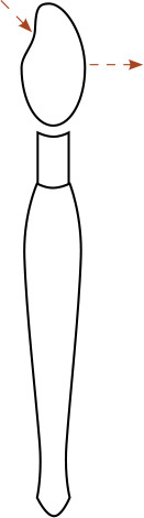
Reshaping objects with the Pencil or Paintbrush tool
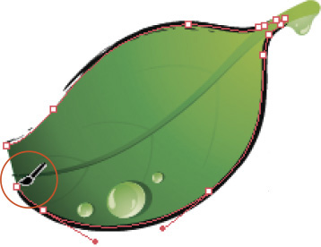
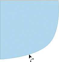
With the Pencil and Paintbrush tools, you can reshape a path by dragging along its edge.
To reshape a path with the Pencil or Paintbrush tool:
1. Do either of the following:
To reshape a path that doesn’t have an applied brush stroke, choose the Pencil tool ![]() (N).
(N).
To reshape a path that does have a brush stroke, choose the Pencil tool ![]() (N) or the Paintbrush tool
(N) or the Paintbrush tool ![]() (B).
(B).
2. Cmd-click/Ctrl-click a path to select it.
3. Position the pointer directly over the edge of the path, then drag along it.C The path will reshape instantly.D

C A path is being reshaped with the Pencil tool.

D The leaf shape was widened.
Note: Be sure to position the pointer precisely on the edge of the path when you begin and finish dragging. If you don’t, you will create a new path instead of reshaping the existing one.
Reshaping segments
You can convert an existing straight segment to a curved segment — or reshape a curved segment — by dragging it with the Pen or Anchor Point tool.
To reshape a path segment with the Anchor Point or Pen tool: ![]()
1. Do either of the following:
Choose the Anchor Point tool ![]() (Shift-C).
(Shift-C).
Choose the Pen tool (P) ![]() and hold down Option/Alt.
and hold down Option/Alt.
2. Let the pointer hover over an existing path segment (the path doesn’t have to be selected); the pointer changes to the Reshape Segment cursor.![]() A
A
A We’re positioning the Anchor Point tool over a curved segment on a path.
3. Do either of the following;
Drag the segment. If the segment was curved, it will reshape according to the direction in which you drag;B if the segment was straight, it will become curved.C–D
B We’re dragging the segment.
C We’re positioning the Anchor Point tool over a straight segment
D We’re dragging the straight segment upward, converting it to a curve.
To make the segment into a symmetrical curve (make its direction handles parallel to each other), drag it with Shift held down.E
E Here we’re dragging the same straight segment upward, except this time with Shift held down, to make the direction handles parallel to each other.
![]() You can also use the above technique to reshape a segment while drawing a new path with the Pen tool. To resume drawing, release Option/Alt.
You can also use the above technique to reshape a segment while drawing a new path with the Pen tool. To resume drawing, release Option/Alt.
By default, when you drag a curved segment on a path, the handles are unconstrained — or if you prefer, you can constrain the handles to parallel alignment by holding down Shift.
To reshape a curved path segment with the Direct Selection tool: ![]()
1. Choose the Direct Selection tool (A).![]() Deselect, then click a path.
Deselect, then click a path.
2. Drag a segment; the cursor changes to the Reshape Segment cursor.![]() The edits will be unconstrained, just as they are when you use the Anchor Point tool or Pen tool. If you want to make a symmetrical curve with parallel direction handles, drag with Shift held down.
The edits will be unconstrained, just as they are when you use the Anchor Point tool or Pen tool. If you want to make a symmetrical curve with parallel direction handles, drag with Shift held down.
Note: If you drag a straight segment with the Direct Selection tool, the segment will move without being reshaped (this is the legacy behavior).
![]() To copy a path segment while reshaping it with the Direct Selection tool, drag it with Option/Alt held down. The copy will be a new, separate path.
To copy a path segment while reshaping it with the Direct Selection tool, drag it with Option/Alt held down. The copy will be a new, separate path.
Applying a variable width profile preset to an object’s stroke
Using the new Profile options, you can quickly apply a preset, nonuniform width to an object’s stroke, to make it look more hand drawn.
To apply a variable width profile preset to an object’s stroke:
1. Select or isolate a path and apply a stroke color.
2. Display the full Stroke panel,![]() then do all of the following:
then do all of the following:
Choose a stroke Weight of 6 pt. or greater.A
A The stroke widths in the original artwork are uniform and boring.
Make sure the Align Stroke to Center button is active.
From the Profile menu, choose a width profile.B–C
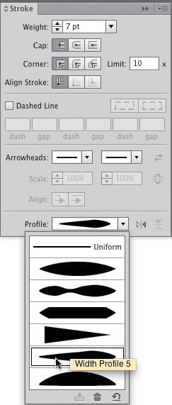
B We are choosing Width Profile 5 from the Profile menu on the Stroke panel.
C The variable width profile gives the line work pizzazz.
3. Optional: To flip the width profile along the path, click the Flip Along button.![]() D (The change will be noticeable only if you apply a profile in which the starting and ending widths are different, such as in Width Profile 2, Width Profile 4, or Width Profile 5.)
D (The change will be noticeable only if you apply a profile in which the starting and ending widths are different, such as in Width Profile 2, Width Profile 4, or Width Profile 5.)
D We clicked the Flip Along button to flip the starting and ending thicknesses of the current stroke profile.
![]() You can also choose a profile from the Variable Width Profile menu on the Control panel.
You can also choose a profile from the Variable Width Profile menu on the Control panel.
Note: To restore the default stroke profile at any time, select or isolate the object, then choose Uniform from the Profile menu (Stroke panel) or the Variable Width Profile menu (Control panel).
![]() If an object that you have selected or targeted has a variable width profile, an asterisk will display next to the stroke weight value on the Appearance panel.
If an object that you have selected or targeted has a variable width profile, an asterisk will display next to the stroke weight value on the Appearance panel.
Changing an object’s stroke width using the Width tool
Using the Width tool, you can change the width profile of an object’s stroke manually.
To reshape an object’s stroke using the Width tool:
1. Select or isolate a path, and apply a stroke color and Weight (not 0). (It can have an Art or Pattern brush applied to it, but not another type of brush.) On the Stroke panel,![]() make sure the Align Stroke to Center button is active.
make sure the Align Stroke to Center button is active.
2. Choose the Width tool ![]() (Shift-W).
(Shift-W).
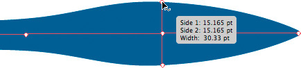
3. Move the pointer over a segment of a closed or open path, or over the endpoint of an open path. Click to make a width point (hollow diamond) appear, then drag outward from the path to lengthen the handles or inward to shorten them, A–B or Option-drag/Alt-drag one of the handles to change its length independently of its mate.C
A To widen this path symmetrically, we dragged outward from it using the Width tool.
B To flare the end of the stroke, we dragged from an endpoint outward using the Width tool.

C Here we are holding down Option/Alt while dragging a handle to move it independently of its mate.
4. Do any of the following optional steps:
Drag any width point along the path to a new location, or Shift-drag a point to move that point along with other width points.
To duplicate a point, drag it with Option/Alt held down.
To delete a point, click it, then press Delete/Backspace.
![]() To move multiple width points, Shift-click those points, release Shift, then drag with the Width tool. To deselect a selected width point, press Esc.
To move multiple width points, Shift-click those points, release Shift, then drag with the Width tool. To deselect a selected width point, press Esc.
To adjust the stroke width by entering values:
1. Follow steps 1 and 2 above. Create width points or choose a width profile preset.
2. Double-click the path or an existing width point to open the Width Point Edit dialog.D
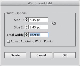
D To move both handles outward, we are entering a Total Width value in the Width Point Edit dialog.
3. Click the Adjust Widths Proportionately icon,![]() if desired, to lengthen or shorten both handles simultaneously, then change the Side 1 and/or Side 2 values for the length of one or both handles; or choose a Total Width value for the combined length of both handles. For a more gradual change in width, allow handles on neighboring width points to adjust along with the selected one by checking Adjust Adjoining Width Points.
if desired, to lengthen or shorten both handles simultaneously, then change the Side 1 and/or Side 2 values for the length of one or both handles; or choose a Total Width value for the combined length of both handles. For a more gradual change in width, allow handles on neighboring width points to adjust along with the selected one by checking Adjust Adjoining Width Points.
4. Click OK.
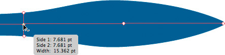
On the preceding page you produced continuous width points using the Width tool. Here you will produce discontinuous points, for more abrupt changes in the stroke width.
To create a discontinuous width point:
1. Follow one of the tasks on the preceding two pages to make the stroke width on a path nonuniform, using three or more width points.
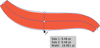
2. Select the Width tool ![]() (Shift-W), then click an existing width point on the path or create a new one. For the sake of this exercise, drag outward from the path to make the stroke fairly wide.A
(Shift-W), then click an existing width point on the path or create a new one. For the sake of this exercise, drag outward from the path to make the stroke fairly wide.A
A We used the Width tool to add a width point to this path, then lengthened its handles.
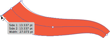
3. Drag an adjacent width point B on top of the one for which you just lengthened the handles.C It is now a discontinuous width point.D–E
B We located an adjacent width point on the same path with the Width tool...
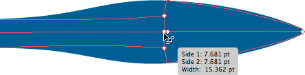
C ... then dragged that adjacent point over the point we had created. It is now a discontinuous point.

D The result is an abrupt change in the stroke width.

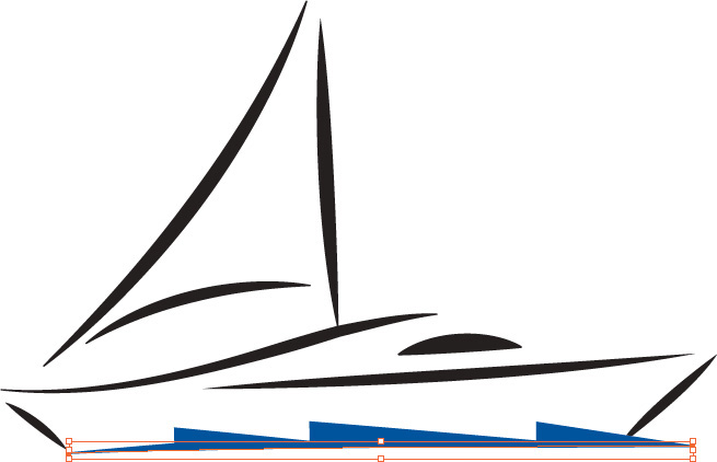
E To add the stylized water objects below this boat, we made the width points on the royal blue stroke discontinuous, saved our custom width profile as a preset, then applied the new preset to two other paths. (We also clicked the Flip Along option for the profile on the middle path to change its orientation.)
4. A discontinuous width point has two pairs of handles. To adjust the length of either pair, position the Width tool on the edge of the narrower or wider part of the stroke to locate a handle, then drag inward or outward from the path.
![]() You can double-click a discontinuous point with the Width tool to open the Width Point Edit dialog (A), then enter specific values to adjust the length of each pair of handles. If you want to remove a pair of handles, check Single Width Only.
You can double-click a discontinuous point with the Width tool to open the Width Point Edit dialog (A), then enter specific values to adjust the length of each pair of handles. If you want to remove a pair of handles, check Single Width Only.
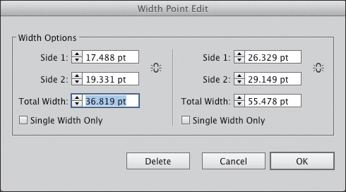
A Double-click a discontinuous width point to open the Width Point Edit dialog, then edit the values for either or both pairs of handles.
![]() To convert one discontinuous width point back into two standard continuous ones, with the Width tool, drag the point along the path; it will separate into two points.
To convert one discontinuous width point back into two standard continuous ones, with the Width tool, drag the point along the path; it will separate into two points.
If you create a custom profile preset that you like, you can save it for future use.
To create a width profile preset:
1. Use the Width tool ![]() to alter the stroke width of a path, and keep the path selected.B
to alter the stroke width of a path, and keep the path selected.B
B We created a custom stroke width on the blue path, and kept the path selected.
2. At the bottom of the Variable Width Profile menu on the Control panel or the Profile menu on the extended Stroke panel, click the Add to Profiles button.![]() C Enter a name for the profile in the dialog, then click OK.
C Enter a name for the profile in the dialog, then click OK.

C On the Variable Width Profile menu, we are clicking the Add to Profiles button.
3. The new profile appears at the bottom of both menus, and is available for all documents.D
D Our custom profile appears on the Variable Width Profile menu.
![]() You can restore all the default profiles to the Variable Width Profile and Profile menus by clicking the Reset Profiles button
You can restore all the default profiles to the Variable Width Profile and Profile menus by clicking the Reset Profiles button ![]() on either menu, but be aware that when you click OK in the alert dialog,E Illustrator will discard all custom profiles on the menus. Ouch!
on either menu, but be aware that when you click OK in the alert dialog,E Illustrator will discard all custom profiles on the menus. Ouch!

E If you click the Reset Profiles button, this alert dialog will display.
Reshaping objects with the Blob Brush tool
In addition to being a great tool for producing “magic marker” type drawings, as we showed you on page 89, you can drag with the Blob Brush tool to reshape or smooth the edges of existing closed paths. It can be used on any object that has a stroke of None: an ordinary path, a compound path, a masked object within a clipping mask, or the start or end object of a live blend.
To reshape an object with the Blob Brush tool:
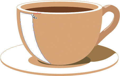
1. Select or isolate an object that was created with any tool except a type or symbol tool,A and make sure it has a stroke color of None.![]() It can contain a solid fill color, a pattern, a gradient, or a graphic style.
It can contain a solid fill color, a pattern, a gradient, or a graphic style.

A To add shading to the cup, we created a basic polygon shape to use as a starting point, and kept it selected.
2. Choose the Blob Brush tool ![]() (Shift-B).
(Shift-B).
3. To add to the object, draw strokes that cross it at some point. Your strokes will merge with the closed path.B Note: If you create a hole with the tool (e.g., draw a loop), the resulting object will be a compound path; to learn about compound paths, see pages 364–366.

B We used the Blob Brush tool to reshape the new object, to make it fit better on the side of the cup.
To smooth the edge of the object by eliminating anchor points, make sure the path is selected and hold down Option/Alt to access the Smooth tool temporarily, then drag along an edge of the object.
![]() Press [ or ] to decrease or increase the diameter of the Blob Brush tool. To choose other options for the tool, see page 90.
Press [ or ] to decrease or increase the diameter of the Blob Brush tool. To choose other options for the tool, see page 90.
The versatile Blob Brush tool can also be used to merge multiple objects, but in a unique way — by drawing strokes across them.
To combine objects using the Blob Brush tool:
1. Arrange two or more closed paths near or overlapping each other (no type objects), and select them. They must have the same solid fill color, pattern, or gradient and a stroke of None, and they must be on the same layer (to restack objects, see page 191). They may not contain a graphic style.
2. With the Blob Brush tool,![]() draw strokes that cross the objects. Note: If your strokes produce a hole (as in a loop), the result will be a compound path.
draw strokes that cross the objects. Note: If your strokes produce a hole (as in a loop), the result will be a compound path.
EXERCISE: Draw and reshape objects in a freehand style
To master the art of drawing shapes by hand, you can use the Blob Brush tool to draw and reshape an object,A–B then erase any unwanted parts of it with the Eraser tool.C Finally, you can use the Smooth tool to smooth out any rough edges.D By using this great trio of tools, you can reshape a path without having to fiddle with any anchor points or direction handles.

A To create foam on the top of a glass, we double-clicked the Blob Brush tool, checked Merge Only with Selection, clicked OK, then drew some shapes with the Blob Brush tool.

B We selected each new shape and used the Blob Brush tool to fill them in. We also reshaped the tan object to create “drips.”
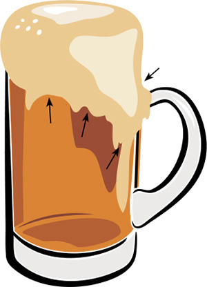
C We used the Eraser tool to clean up the edges of the drip shapes.
D Finally, we used the Smooth tool to smooth some of the rough edges.
Using the Reshape tool
The Reshape tool does a nice job of changing the contour of a path gently without distorting its shape. Give it a try and see if you like it. Note: Unfortunately, Smart Guides don’t work with this tool.
To use the Reshape tool:
1. Choose the Direct Selection tool ![]() (A), deselect, then click the edge of a path. Only one point or segment should be selected.
(A), deselect, then click the edge of a path. Only one point or segment should be selected.
2. Choose the Reshape tool ![]() (it’s on the same fly-out menu as the Scale tool).
(it’s on the same fly-out menu as the Scale tool).
3. Do one of the following:
Drag any visible anchor point on the path. A tiny square border will display around the point when you release the mouse.
Drag any segment of the path. A new square border point is created.
Shift-click or marquee multiple anchor points on the path (a square will display around each one), then drag one of the square points. The selected portion of the path will maintain its overall contour as it elongates or contracts, and the rest of the path will stay put.
EXERCISE: Create a brush with the Reshape tool
A With the Rectangle tool (M), draw a narrow vertical rectangle. Press D to apply the default fill and stroke colors.
B Deselect, then with the Direct Selection tool, click the path. With the Reshape tool, drag the bottom segment downward.
C Drag the upper part of the right and left vertical segments outward.
D To reshape the handle, drag the top segment downward and drag the lower part of the vertical segments inward.
E With the Rectangle tool, draw a small vertical rectangle. Via the Layers panel, restack it below the handle listing. With the Selection tool, drag it downward so its bottom edge is hidden by the handle.
F Deselect, then with the Direct Selection tool, click the path. With the Reshape tool, drag the middle of the top segment of the rectangle downward.
G With the Ellipse tool (L), draw an oval for the bristles, then with the Selection tool, position it at the top of the brush. Deselect, then with the Direct Selection tool, click the edge of the oval.
With the Reshape tool, drag the upper left segment inward and the right middle point outward.

H Drag the top point upward to elongate the tip. Apply some fill colors and you’re done. (You could also change the stroke settings or, as we did, apply a stroke of None.)
Erasing sections of objects
The Eraser tool removes parts of objects that it passes over. The remaining parts of the objects are reconnected automatically to form closed paths.
To erase parts of objects:
1. If you want to limit the effect of the Eraser tool to specific objects (perhaps if there are many objects close together in your artwork, and you want to erase only some of them), select those objects first or put an object into isolation mode. Otherwise, deselect all.A

A We drew this mountain range with the Pencil tool.
Note: The object can be a Live Paint object or a compound path, it can be in a clipping mask, and it may contain gradients or patterns. It cannot be a type object, an object in a blend, or an object in a distortion envelope.
2. Choose the Eraser tool ![]() (Shift-E).
(Shift-E).
3. Do either of the following:
Drag across parts of objects to be erased.B–C Hold down Shift while dragging to draw straight strokes at increments of 45°.
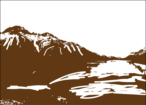
B With the Eraser tool, we erased sections of the object to create details in the mountains and lake.

C With a smaller diameter chosen for the Eraser tool, we made more erasures. Finally, we placed two colored rectangles behind the mountain layer.
Option-drag/Alt-drag to create a temporary rectangle. Any parts of the artwork that fall within the rectangle will be erased.
![]() Press [ or ] to decrease or increase the diameter of the Eraser tool. Double-click the tool icon to choose options for the tool shape.
Press [ or ] to decrease or increase the diameter of the Eraser tool. Double-click the tool icon to choose options for the tool shape.
![]() If you drag with the Eraser tool on the inside of an object — without crossing over the edge — the result will be a compound path.
If you drag with the Eraser tool on the inside of an object — without crossing over the edge — the result will be a compound path.
Using the Path Eraser Tool
To erase parts of a path without having to click points, choose the Path Eraser tool ![]() (the last tool on the Pencil tool fly-out menu). Select a path, then drag the eraser of the pencil pointer along the path.
(the last tool on the Pencil tool fly-out menu). Select a path, then drag the eraser of the pencil pointer along the path.

Aligning points
The Align buttons on the Control panel precisely realign selected endpoints or anchor points along the horizontal and/or vertical axis, and as a result, the paths to which those points belong are reshaped.
To align points:
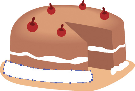
1. Choose the Lasso tool ![]() (Q).
(Q).
2. Drag to select two or more endpoints or anchor points A on the same path or on different paths.

A We selected two anchor points.
3. On the Control panel, do any of the following:
To align the points by moving them along the horizontal (x) axis, click one of the three Horizontal Align buttons.
To align the points by moving them along the vertical (y) axis, click one of the three Vertical Align buttons.
To overlap the points along both the horizontal and vertical axes, click a Horizontal Align button, then click a Vertical Align button. Use this method if you’re planning to join the points into one point (see “To join two endpoints into one point” on the facing page).
If you click a Left, Right, Top,B or Bottom C Align button, points will align to the leftmost, rightmost, topmost, or bottommost selected point, respectively. If you click a Center Align button,D points will align to a location that is equidistant between the points.
B We clicked the Vertical Align Top button.

C We clicked the Vertical Align Bottom button.

D We clicked the Vertical Align Center button.
![]() If you Shift-select points with the Direct Selection tool (instead of selecting them via dragging) before clicking an align button, points will align with and move toward the last point you select (called the key anchor point), regardless of which Horizontal or Vertical Align button you click.
If you Shift-select points with the Direct Selection tool (instead of selecting them via dragging) before clicking an align button, points will align with and move toward the last point you select (called the key anchor point), regardless of which Horizontal or Vertical Align button you click.
![]() To align selected points via a command, right-click and choose Average (Cmd-Option-J/Ctrl-Alt-J), then click Axis: Horizontal, Vertical, or Both in the dialog (the Control panel provides more options).
To align selected points via a command, right-click and choose Average (Cmd-Option-J/Ctrl-Alt-J), then click Axis: Horizontal, Vertical, or Both in the dialog (the Control panel provides more options).
Joining endpoints
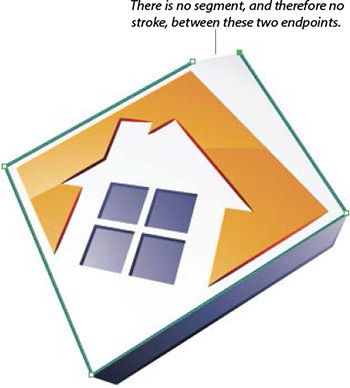
You can use the join controls in Illustrator to connect nonoverlapping endpoints with a new straight segment, or to join overlapping endpoints into one anchor point. Endpoints can be joined on the same open path (to close the path) or on separate open paths (to join them together).
To connect two endpoints with a segment:
1. Do either of the following:
With the Direct Selection tool ![]() (A) or the Lasso tool
(A) or the Lasso tool ![]() (Q), drag to select two (or more) endpoints.A
(Q), drag to select two (or more) endpoints.A
A We selected two endpoints.
With the Selection tool ![]() (V) or the Layers panel, select one or more open paths. The objects can be in a group but they can’t be compound paths, paths in a Live Paint group, or type objects.
(V) or the Layers panel, select one or more open paths. The objects can be in a group but they can’t be compound paths, paths in a Live Paint group, or type objects.
2. Do one of the following: B
B The Connect Selected End Points button created a straight segment between them.
Press Cmd-J/Ctrl-J (Object > Path > Join).
Right-click in the document and choose Join.
If you selected endpoints (not whole objects), you can click the Connect Selected End Points button ![]() on the Control panel.
on the Control panel.
Note: If you select multiple whole open paths with the Selection tool, the Join command will join the endpoints that are closest to each other. The attributes from the upper path (as listed on the Layers panel) will be applied to the newly combined object.
To join two endpoints into one point:
1. With the Direct Selection tool ![]() (A) or the Lasso tool
(A) or the Lasso tool ![]() (Q), drag to select two endpoints.
(Q), drag to select two endpoints.
2. Do either of the following: C

C This is figure A after we clicked the Horizontal Align Center and Vertical Align Center buttons, then clicked the Connect Selected End Points button on the Control panel.
Press Cmd-Option-Shift-J/Ctrl-Alt-Shift-J.
On the Control panel, click one of the three Horizontal Align buttons and one of the three Vertical Align buttons to position the two selected endpoints directly on top of each other, then do one of the following: Press Cmd-J/Ctrl-J, or click the Connect Selected End Points button ![]() on the Control panel, or right-click in the document and choose Join.
on the Control panel, or right-click in the document and choose Join.
Reshaping objects using commands
Some of the commands on the Effect menu can be used to explode simple shapes into more complex ones, with practically no effort on your part. For example, the Zig Zag effect, used in the steps below, adds anchor points to a path and then moves those points to produce waves or zigzags. Best of all, the Effect menu commands don’t alter the actual path, so the results are both editable and removable. To explore effects more in depth, see Chapter 15.
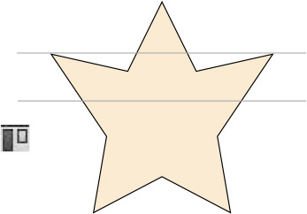
To apply the Zig Zag effect:
1. Select an object. On the Appearance panel,![]() click below the Opacity listing to make sure the Stroke and/or Fill listings are deselected.
click below the Opacity listing to make sure the Stroke and/or Fill listings are deselected.
2. From the Add New Effect menu ![]() on the Appearance panel, choose Distort & Transform > Zig Zag.
on the Appearance panel, choose Distort & Transform > Zig Zag.
3. The Zig Zag dialog opens.A Check Preview. Click Points: Smooth (at the bottom of the dialog) to create curvy waves, or Corner to create sharp-cornered zigzags.
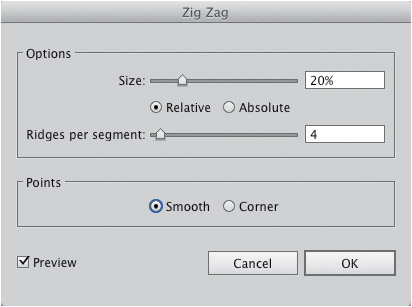
A Choose settings for the Zig Zag effect.
4. Do either of the following:
To move the added points by a percentage relative to the size of the object, click Relative, then move the Size slider.
To move the added points by a specified distance, click Absolute, then specify that distance via the Size slider or field.
5. Choose a number of Ridges Per Segment for the number of anchor points to be added between existing points. The greater the number of ridges, the more complex the resulting object. If you enter a number, press Tab to preview its effect.
6. Click OK.B–E

B The original object is a star.
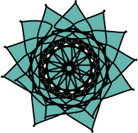
C The Zig Zag effect is applied (Size 20%, Relative, Ridges 4, Smooth).

D The original object is a circle.

E The Zig Zag effect is applied (Size 24%, Relative, Ridges 20, Corner).
![]() To edit the settings for the effect at any time, select the object, then click Zig Zag on the Appearance panel.
To edit the settings for the effect at any time, select the object, then click Zig Zag on the Appearance panel.
![]() To apply the Zig Zag effect to just an object’s stroke, select the object, click the Stroke listing on the Appearance panel, then follow steps 2–6 above.F–G You could also try this with the Distort & Transform > Pucker & Bloat or Twist effect. To view the effect listing on the Appearance panel, click the expand arrowhead for the Stroke listing.
To apply the Zig Zag effect to just an object’s stroke, select the object, click the Stroke listing on the Appearance panel, then follow steps 2–6 above.F–G You could also try this with the Distort & Transform > Pucker & Bloat or Twist effect. To view the effect listing on the Appearance panel, click the expand arrowhead for the Stroke listing.
F The original object is a circle.

G The Zig Zag effect is applied to just the object’s stroke (Size 9%, Relative, Ridges 4, Smooth).
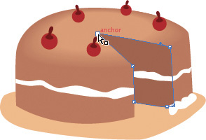
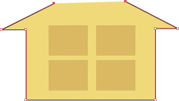
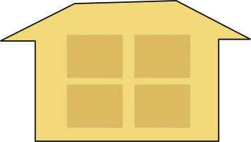
If you use one of the “easy” tools to create objects, such as the Rectangle, Ellipse, Star, Blob Brush, Pencil, or Paintbrush, followed by any of the simpler reshaping techniques that are covered in this chapter, you will be able to create artwork that looks complex without having to painstakingly draw it with the Pen tool. One of the easiest ways to create illustrations is to combine objects via a command on the Pathfinder panel. For example, to combine whole objects, rather than joining points one pair at a time, you can simply click the Unite button on the Pathfinder panel, as in the following steps.
To combine objects using a command:
1. Position two or more objects so they overlap one another at least partially.A
A Arrange two or more objects so they overlap, then select them.
2. With any selection tool, marquee at least some portion of all the objects.
3. Display the Pathfinder panel.![]()
4. Click the Unite (first) button ![]() on the panel. Voilà! The individual objects are now combined into one closed object or compound path. It will automatically be given the attributes of the object that was originally on top.B–F
on the panel. Voilà! The individual objects are now combined into one closed object or compound path. It will automatically be given the attributes of the object that was originally on top.B–F

B The Unite button on the Pathfinder panel was clicked to combine the separate shapes into one compound shape.
C The original artwork consists of four objects.

D The Unite command is applied.

E The original artwork consists of four objects.

F The Unite command is applied (Macintosh becomes Granny Smith!).
![]() To learn more about this panel, and also about the Shape Builder tool, see Chapter 25.
To learn more about this panel, and also about the Shape Builder tool, see Chapter 25.
![]() To learn about compound paths, see pages 365–367.
To learn about compound paths, see pages 365–367.
Slicing and dicing
The Scissors tool either opens a closed path or splits one open path into two. You can split a path either at an anchor point or in the middle of a segment.
To split a path with the Scissors tool:
1. Choose any selection tool, then click an object to display its points.
2. Choose the Scissors tool ![]() (C).
(C).
3. Click the object’s path: If you click once on a closed path, it will turn into a single open path; if you click once on an open path, it will be split into two paths.
If you click a segment, two new endpoints will appear, one on top of the other. If you click an anchor point, a new anchor point will appear on top of the existing one, and it will be selected.A
A We clicked an anchor point with the Scissors tool. You can click an anchor point or a segment.
4. To move the new endpoints apart, choose the Direct Selection tool ![]() (A), then either drag the selected endpoint away from its mate or press an arrow key.B
(A), then either drag the selected endpoint away from its mate or press an arrow key.B
B We moved the new endpoint on our newly opened path.
To split a path via the Control panel:
1. Choose the Direct Selection tool ![]() (A).
(A).
2. Click a path to display its anchor points, then click an anchor point to select it.
3. Click the Cut Path at Selected Anchor Points button ![]() on the Control panel. A new anchor point will appear on top of the existing one, and it will be selected.
on the Control panel. A new anchor point will appear on top of the existing one, and it will be selected.
4. To move the two new endpoints apart, drag the selected one.
The Divide Objects Below command uses an object like a cookie cutter to cut the objects below it, then deletes the cutting object.
To cut objects via the Divide Objects Below command:
1. Create or select an object to be used as a cutting shape. It can’t be a group or a Live Paint group.
Optional: The Divide Objects Below command is going to delete the cutting object, so you may want to Option-drag/Alt-drag it to copy it first.
2. Place the cutting object on top of the object(s) to be cut.A

A The white leaf shape will be used as a cutting object (there are three objects below it).
3. Make sure only the cutting object is selected.
4. Choose Object > Path > Divide Objects Below. The topmost shape (the cutting object) is deleted and the underlying objects are cut into separate paths where they met the edge of the cutting object.B–C
B The Divide Objects Below command used the leaf shape to cut through the underlying objects.

C We applied different fill colors to the resulting divided paths.
5. Deselect. You can use the Selection tool to select or isolate, then recolor or move, any of the resulting (newly cut) objects. Any cut objects that were originally in a group will remain so.
![]() To prevent an object that is stacked below the cutting shape from being affected by the Divide Objects Below command, you can either lock it (see page 193) or hide it (see page 194).
To prevent an object that is stacked below the cutting shape from being affected by the Divide Objects Below command, you can either lock it (see page 193) or hide it (see page 194).
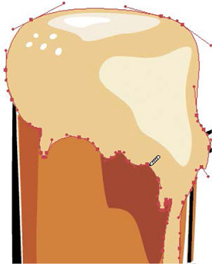
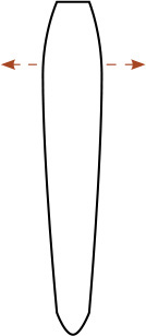
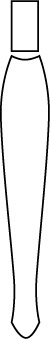
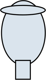
EXERCISE: Draw a glass of beer (or cream soda!)
1. With the Ellipse tool ![]() (L), draw a vertical oval that is approximately 3.5’’ wide by 5.5’’ high, and also a smaller horizontal oval. With the Rectangle tool
(L), draw a vertical oval that is approximately 3.5’’ wide by 5.5’’ high, and also a smaller horizontal oval. With the Rectangle tool ![]() (M), draw a rectangle at the bottom of the vertical ellipse.
(M), draw a rectangle at the bottom of the vertical ellipse.
2. With the Selection tool,![]() select all three shapes. Open the Art History > Impressionism library of swatches, then apply a pale blue-gray fill and a black stroke.A On the Pathfinder panel, click the Unite button.
select all three shapes. Open the Art History > Impressionism library of swatches, then apply a pale blue-gray fill and a black stroke.A On the Pathfinder panel, click the Unite button.![]()
A
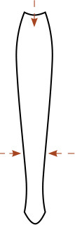
3. With the Delete Anchor Point tool ![]() (-), click to delete the points shown in B.
(-), click to delete the points shown in B.
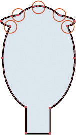
B
4. With the Direct Selection tool ![]() (A), drag to select the four bottom points of the stem. Click the Convert Selected Anchor Points to Smooth button
(A), drag to select the four bottom points of the stem. Click the Convert Selected Anchor Points to Smooth button ![]() on the Control panel. Deselect. To reshape the stem, as shown in,C click each point, then press an arrow key; move two points inward and two points outward. Use the Reshape Segment cursor
on the Control panel. Deselect. To reshape the stem, as shown in,C click each point, then press an arrow key; move two points inward and two points outward. Use the Reshape Segment cursor ![]() to reshape the bottom curve of the stem.
to reshape the bottom curve of the stem.![]()
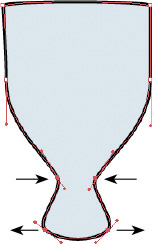
C
5. With the Ellipse tool, Option-drag/Alt-drag to create an oval the same width as the glass top, scale it to fit the glass, and fill it with a cream color.D With the Add Anchor Point tool ![]() (+), add five new points along the top of the oval. With the Direct Selection tool, select and drag each point separately to make the oval look more like foam.E
(+), add five new points along the top of the oval. With the Direct Selection tool, select and drag each point separately to make the oval look more like foam.E
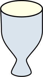
D
E
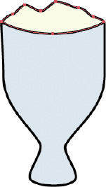
6. With the Selection tool (V), select the glass object. With the Scale tool ![]() (S), start dragging, then hold down Option/Alt and drag diagonally inward to create a slightly smaller copy. Apply a light tan fill color and a stroke of None. With the Delete Anchor Point tool (–), click the bottom two points on the scaled copy. With the Direct Selection tool (A), move the top two corner points on the scaled copy closer to the top corners of the original glass shape.F
(S), start dragging, then hold down Option/Alt and drag diagonally inward to create a slightly smaller copy. Apply a light tan fill color and a stroke of None. With the Delete Anchor Point tool (–), click the bottom two points on the scaled copy. With the Direct Selection tool (A), move the top two corner points on the scaled copy closer to the top corners of the original glass shape.F
F
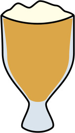
7. Deselect. Double-click the Blob Brush tool.![]() Set the Size to 40 pt, the Angle to 40°, and the Roundness to 22%; click OK. Choose a darker tan fill color (and a Stroke of None), then drag vertically along the right edge of the glass to create shading. Double-click the tool again, change the Angle value to –40°, then click OK. Drag inside the left edge of the glass.G
Set the Size to 40 pt, the Angle to 40°, and the Roundness to 22%; click OK. Choose a darker tan fill color (and a Stroke of None), then drag vertically along the right edge of the glass to create shading. Double-click the tool again, change the Angle value to –40°, then click OK. Drag inside the left edge of the glass.G

G
8. With the Ellipse tool (L), draw an oval for the base of the glass, and apply the same colors as the glass. Via the Layers panel, restack it below the glass object.
9. Reset the angle for the Blob Brush to 0. Create more areas of shading and highlights on the glass and stem. Cheers! H

H