
Chapter 3
Binary Numbering System
In Chapter 2, we saw that the digital computer operates by moving electrical current through its component parts. We must then find a way to convert information into a binary representation. We may then examine how to compute using binary. In this chapter, we study the binary numbering system. The chapter covers conversion methods from binary to decimal and decimal to binary for unsigned (positive) integers, negative integers, fractional, and floating point numbers. The chapter also introduces the octal and hexadecimal numbering systems. Character representations are discussed. The chapter then turns to binary (Boolean) operations and how to compute with them. Finally, the chapter introduces three example uses of binary: network addressing, image files, and parity for error detection and correction.
The learning objectives of this chapter are to
- Provide methods for numeric conversion between bases: decimal, binary, octal, and hexadecimal, for positive and negative integers and floating point numbers.
- Describe how characters are stored in computer memory.
- Demonstrate the application of binary (Boolean) operations of AND, OR, NOT, and XOR on binary numbers.
- Illustrate the use of binary in a computer with a focus on IP addresses, image file storage, and parity bits.
The computer processes and stores information in binary form. So we need to understand what binary is, how to represent information in binary, and how to apply binary (Boolean) operators. This chapter looks at the binary numbering system and a couple of related numbering systems. Although it is critical that a computer scientist understand binary, in information technology (IT) you will find that binary comes up occasionally and so is worth understanding.
Numbering Systems
A numbering system (also known as a numeral system) is a writing system for expressing numbers. In mathematics, there are an infinite number of numbering systems although we tend to largely focus on only two, decimal and binary. Table 3.1 presents the commonly used and historically used numbering systems.
Common Numbering Systems
|
Base |
Name |
Reason Used/Popularity |
|
1 |
Unary |
Used in theoretical computer science when dealing with Turing machines, not very common |
|
2 |
Binary |
Digital computers use binary and therefore is studied in computer-related disciplines |
|
8 |
Octal |
Groups of three binary digits create an octal digit, used in computer-related disciplines to make binary more readable |
|
10 |
Decimal |
Primary human numbering system |
|
16 |
Hexadecimal |
Groups of four binary digits create a hexadecimal digit, used in computer-related disciplines to make binary more readable, easier to read than octal (requires fewer digits) but is more complex because of the inclusion of digits A–F |
|
20 |
Vigesimal |
Used by the Pre-Columbian Mayan civilization; dots and lines represented digits, 0–4 are denoted by 0 to 4 dots, 5–9 are denoted by 0 to 4 dots with an underline, 10–14 are denoted by 0 to 4 dots with 2 underlines, 15–19 are denoted by 0 to 4 dots with 3 underlines; not used outside of the Mayan civilization |
|
60 |
Cuneiform |
Used by the ancient Babylonian civilization |
Formally, we will define a numbering system as base k (k being a positive integer), where
- Any number in this base will contain digits from 0 to k – 1.
- The interpretation of a digit is its value * power.
- The power is based on the column, or position, where power = basecolumn, and where column is counted from the right to the left with the rightmost column being column 0.
For example, decimal is base 10. This means we can use digits 0 through 9. The power will be 10column. If our number is 130, this represents the value 1 * 102 + 3 * 101 + 0 * 100, or 1 in the hundreds column, 3 in the tens column, and 0 in the ones column.
Unary, base 1, is an odd base for two reasons. First, following the definition above, base 1 means that our only digits are 0, but this would mean that all of our possible numbers, say 0000, 0000000000, 0, will all be 0 because the value in the formula value * power is always 0. For this reason, in unary, we will use the digit 1 instead of 0. Second, notice that all of the powers will be 1 (10 = 1, 11 = 1, 12 = 1, 13 = 1). The result is that the number being represented is merely the sum of the number of digits. So, for instance, in unary, 111 is the representation for the value 3, and 111111111 is the representation for the value 9.
Let us consider base 5. For this base, we use only digits 0 to 4 and the “columns” of any number represent from right to left the one’s column, the five’s column, the twenty-five’s column (52), the hundred twenty-five’s column (53), the six hundred twenty-five’s column (54), and so forth. The number 1234 in base 5 is the value 1 * 125 + 2 * 25 + 3 * 5 + 4 * 1 = 194 in decimal.
Given any number anan–1…a1a0 in some base b, the number is interpreted using the following summation ∑ni=0(aj*bi) . That is, we take the rightmost digit and multiply it by b0 and add it to the next rightmost digit and multiply it by b1 and add it to the next rightmost digit and multiply it by b2, …, and add it to the second to leftmost digit (in column n – 1), then multiply it by bn–1 and add it to the leftmost digit (in column n) and multiply it by bn.
Notice that the rightmost column’s power will always be 1 no matter what base. Why is this? The rightmost column will always have a power of basecolumn where column is 0, or base0. In mathematics, any positive integer (1 or greater) raised to the 0th power is always 1.
Since there are an infinite number of numbering systems (any positive k is a legal base), we need to be able to denote what base a number is in. We do this by placing the base as a subscript at the end of the number. So 12345 is 1234 in base 5, which as we saw above is the same as 19410. For convenience sake, we are allowed to omit the base if we are dealing with base 10 (decimal) because that is the default base, so we would say 12345 = 194.
Let us consider a base larger than 10, say base 12. We might have the number 24612. This number is actually 2 * 122 + 4 * 12 + 6 * 1 = 342. But recall that in any base k, we are permitted to use digits 0..k – 1. For base 12, this would be any digits 0–11. Now, we have a problem, because 10 and 11 are not single digits. If I were to write the number 1112, it would look like I meant 1 in the twelve’s column and 1 in the one’s column instead of 11 in the one’s column. This would lead us to have confusion, is 1112 = 13 (a two digit number) or 1112 = 11 (a one-digit number)? So we need to find an alternative way to represent the digits in a base larger than 10. Luckily for us, we tend to only use one base larger than 10, base 16, also known as hexadecimal. For this base, it was decided that the digits used to represent 10, 11, 12, 13, 14, and 15 would be A, B, C, D, E, and F, respectively. Thus, the value 3AB216 means 3 in the 163 column, A (or 10) in the 162 column, B (or 11) in the 161 column and 2 in the one’s column. So what does 3AB216 represent? 3 * 163 + 10 * 162 + 11 * 161 + 2 * 1 = 15,026.
Binary Numbering System
Why is all this important? It would not be if our computers used base 10 (decimal), but computers store all information, transmit all information, and process all information in binary instead of decimal. And although as an IT specialist, you may never have to worry about looking at or expressing data in binary, the use of non-decimal numbering systems does come up from time to time. The most common occurrence of a non-decimal numbering system is that of network communication. IP addresses are sometimes denoted in binary, and IPv6 addresses are denoted in hexadecimal. Octal is also used for various computer applications, but that is happening far less often. In this section, we look first at binary and then octal and hexadecimal.
Binary is probably the most important numbering system outside of decimal. Because of the digital nature of computers (i.e., everything is stored in one of two ways, current or no current), everything has to be represented as ons and offs. So we use binary, where 1 means on and 0 means off. This means that everything the computer stores will have to first be converted into 1s and 0s. We will call a single 1 or 0 value a bit (for binary digit). Data movement requires one wire for every bit so that the transmission of a datum (say of 8 bits) can be done at one time, 1 bit per wire, rather than 1 bit at a time. The digital circuits in the CPU operate on bits, both registers and memory store bits. As a computer scientist or computer engineer, you might occasionally have to look at data or program code in binary. If you were to look at a thousand bits, it would be difficult to focus on it. So instead, we break up our data into groups. Eight bits are placed together into a unit called a byte. It was common in earlier computers that a datum would be stored in one byte, possibly two. A byte, being 8 bits, can store any combination of 8 zeroes and ones, for instance, 11111111, 10101010, 10001000, 00000000, 01111110, and 01011011. There are 256 different combinations of ones and zeroes that can be placed in 8 bits (1 byte). We get that number by simply computing 28 (multiply two together eight times).
The numeric conversion from binary to decimal can be done using the formula from the previous page. However, there is an easier way to think about it. Let us take as an example a byte storing 010101012. According to the formula, we would convert this as 0 * 27 + 1 * 26 + 0 * 25 + 1 * 24 + 0 * 23 + 1 * 22 + 0 * 21 + 1 * 20 = 0 * 128 + 1 * 64 + 0 * 32 + 1 * 16 + 0 * 8 + 1 * 4 + 0 * 2 + 1 * 1 = 85. Notice that every digit in our binary number is either a 0 or a 1, unlike say the base 5 example in the previous section, which allowed digits 0, 1, 2, 3, and 4. When converting from binary to decimal, you do not need to worry about multiplying the digit times the power. Instead, the digit will be a 0, in which case 0 * power = 0 and can be dropped out of the summation, or the digit is a 1, in which case 1 * power = power. Therefore, our summation is merely the powers of 2 of the columns that contain a 1. Going back to the previous example, we really could write 010101012 as 0 + 64 + 0 + 16 + 0 + 4 + 0 + 1 = 85, as shown in Figure 3.1. If we can learn the powers of each column (the powers of 2), then all we are doing is adding up those column values whose associated digits are 1s.
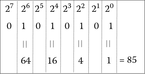
Table 3.2 shows many of the powers of base 2. You get this by starting at 1 and then doubling the number for each higher power (or each column as you move to the left). Notice that the powers of 2 raised to units of 10 (10, 20, 30) are all abbreviated for convenience. 210 = 1024 or 1 K or approximately 1000 (if we do not mind rounding off a little). 220 = 1 M or approximately 1 million (as shown in Table 3.2, the exact value is 1,048,576). 230 = 1 G or approximately 1 billion. 240 = 1 T or approximately 1 trillion. 250 (not shown in the table) = 1 P for a peta, which is approximately 1 quadrillion.
Powers of Two
|
Power of 2 |
Value |
|
20 |
1 |
|
21 |
2 |
|
22 |
4 |
|
23 |
8 |
|
24 |
16 |
|
25 |
32 |
|
26 |
64 |
|
27 |
128 |
|
28 |
256 |
|
29 |
512 |
|
210 |
1,024 |
|
211 |
2,048 |
|
212 |
4,096 |
|
213 |
8,192 |
|
214 |
16,384 |
|
215 |
32,768 |
|
216 |
65,536 |
|
220 |
1,048,576 |
|
230 |
1,073,741,824 |
|
240 |
1,099,511,627,776 |
Let us try to put the powers of 2 in Table 3.2 to use. Given any binary number, just add up the power of 2 from the chart in Table 3.2 based on the location of the 1s, where the rightmost digit represents the value 20. For instance, 1101 would contain a 23, a 22, but no 21, and a 20, or 23 + 22 + 20 = 8 + 4 + 1 = 13. We will stick with byte-long numbers (8 bits) for simplicity.
11000110: 27 + 26 + 22 + 21 = 128 + 64 + 4 + 2 = 198
10101010: 27 + 25 + 23 + 21 = 128 + 32 + 8 + 2 = 170
01000111: 26 + 22 + 21 + 20 = 64 + 4 + 2 + 1 = 71
00001110: 23 + 22 + 21 = 8 + 4 + 2 = 14
00110011: 25 + 24 + 21 + 20 = 32 + 16 + 2 + 1 = 51
00000000: 0
11111111: 27 + 26 + 25 + 24 + 23 + 22 + 21 + 20 =
128 + 64 + 32 + 16 + 8 + 4 + 2 + 1 = 255
Notice in this last case, we have the largest 8-bit number, which is equal to 28 – 1.
What about converting from decimal to binary? There are two strategies that we can apply. Below is the traditional strategy, but another—possibly easier—strategy will be shown next.
Take the decimal value and divide by 2. Take the quotient and divide by 2. Continue doing this until you are left with 0. Record the remainders of the division (the remainder when dividing by 2 will either be a 1 or 0). The collection of remainders in reverse order (or from bottom up) is the binary value. For example, let us try 89:
89/2 = 44 with a remainder of 1
44/2 = 22 with a remainder of 0
22/2 = 11 with a remainder of 0
11/2 = 5 with a remainder of 1
5/2 = 2 with a remainder of 1
2/2 = 1 with a remainder of 0
1/2 = 0 with a remainder of 1
We are done (we have reached 0). The binary equivalent of 89 is 01011001 (the remainders in reverse order, with an added bit in the front to make it an 8-bit number). We can confirm this by converting this number back to decimal: 01011001 = 64 + 16 + 8 + 1 = 89.
Let us try another one, 251:
251/2 = 125 with a remainder of 1
125/2 = 62 with a remainder of 1
62/2 = 31 with a remainder of 0
31/2 = 15 with a remainder of 1
15/2 = 7 with a remainder of 1
7/2 = 3 with a remainder of 1
3/2 = 1 with a remainder of 1
1/2 = 0 with a remainder of 1
So 251 is 11111011. We convert back to check, 11111011 = 128 + 64 + 32 + 16 + 8 + 2 + 1 = 251.
The division approach is simple although not necessarily intuitive, because you have to reverse the order of the remainders to form the binary number. Another way to convert from decimal to binary is to use subtractions. Given a decimal number, identify the largest power of 2 that can be subtracted from it while still leaving a positive number or 0. Do this until your decimal number is 0. For each power of 2 that is subtracted into the number, write a 1 in that corresponding column.
Let us consider as an example the same value we just converted, 251. Referring back to Table 3.2, the largest power of 2 that can we can subtract from 251 is 128. In subtracting 128 from 251, we have 123. The largest power of 2 that we can subtract from 123 is 64, leaving 59. The largest power of 2 that we can subtract from 59 is 32 leaving 27. The largest power of 2 we can subtract from 27 is 16 leaving 11. The largest power of 2 we can subtract from 11 is 8, leaving 3. The largest power of 2 we can subtract from 3 is 2 leaving 1. The largest power of 2 we can subtract from 1 is 1 leaving 0. We are done. Our conversion process went like this:
251 – 128 = 123
123 – 64 = 59
59 – 32 = 27
27 – 16 = 11
11 – 8 = 3
3 – 2 = 1
1 – 1 = 0
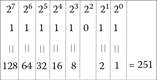
Thus, 251 = 128 + 64 + 32 + 16 + 8 + 2 + 1. So our binary equivalent has 1s in the columns representing 128, 64, 32, 16, 8, 2, and 1 and 0s elsewhere (the only other column represents 4). This gives us 11111011. We can check our work, as shown in Figure 3.2, which converts 11111011 back to decimal, 251.
Let us do another example. Convert 140 into binary. The largest power of 2 that we can subtract into 140 is 128 leaving 12. The largest power of 2 that we can subtract into 12 is 8 leaving 4. The largest power of 2 that we can subtract into 4 is 4 leaving 0.
140 – 128 = 12
12 – 8 = 4
4 – 4 = 0
140 = 128 + 8 + 4. So we have 1s in the columns that represent 128, 8, and 4, 0s elsewhere. This is the value 10001100, so 140 = 10001100.
So far, we have limited our binary numbers to 8 bits. Recall that with 8 bits, we have 256 different combinations of 1s and 0s. Since 00000000 is 0, the 8 bit (1 byte) range of values is 0 to 255. What if we want to store a larger number? Then we need more bits. For instance, in 2 bytes (16 bits), we can store any number from 0 to 65535. Recall that 216 = 65536. In general, if we have n bits, we can store any number from 0 to 2n – 1. Although we will often use the byte as a convenient amount of storage (instead of 1 or a few bits), limiting ourselves to 1 byte is too restrictive. Today’s computers typically provide 32 bits (4 bytes) or 64 bits (8 bytes) for the typical storage size. We refer to the typical storage size as the computer’s word size.
How big is 32 bits? It gives us this range of values:
00000000000000000000000000000000 = 0
…
11111111111111111111111111111111 = 4294967296 (nearly 4.3 billion)
For most applications, 32 bits gives us ample space for storage. In 64 bits, the largest number we can store is more than 18 quadrillion (18 followed by 15 zeroes!) These are huge numbers. Are 32- or 64-bit word sizes wasteful of memory? It depends on the application. However, with memory sizes of at least 4 billion bytes and disk storage of at least half a trillion bytes, using 32 or 64 bits to store numbers should not be a cause for concern.
Consider having to look at a series of numbers stored in 32-bit binary values. Because all of the digits are 1 and 0 and because there are a lot of them, the resulting list becomes very difficult to look at, almost like looking at an optical illusion. For convenience, we may translate binary numbers into different representations, commonly octal (base 8) or hexadecimal (base 16). Let us try with the following list. Imagine pages and pages of this stuff!
11101100100010110010101100000111
00101100010100101010110110010001
10001011001001001011011100100111
10001000101001111010001110101011
00001001010100000111100010101100
You might notice that 8 and 16 are multiples of 2. This makes translating from base 2 to base 8 or base 16 simple (as compared to translating from base 2 to base 10 or base 10 to base 2). For base 8, take 3 binary bits and group them together and then convert those 3 bits from binary to octal. This works because 23 = 8. Note that because octal uses only eight digits (0 to 7), converting 3 bits from binary to octal is the same as converting 3 bits from binary to decimal. Table 3.3 shows you how to convert 3 bits between the two bases.
Binary to Octal Conversion Table
|
Binary |
Octal |
|
000 |
0 |
|
001 |
1 |
|
010 |
2 |
|
011 |
3 |
|
100 |
4 |
|
101 |
5 |
|
110 |
6 |
|
111 |
7 |
Using the first 32-bit number from the previous page, we will convert it to octal.
11101100100010110010101100000111
First, divide the 32-bit number into 3-bit segments starting from the right end
11 101 100 100 010 110 010 101 100 000 111
Second, since the leftmost segment is not 3 bits, we add leading 0s to make it 3 bits
011 101 100 100 010 110 010 101 100 000 111
Third, using the above table, we convert each group of 3 bits into its equivalent octal value
3 5 4 4 2 6 2 5 4 0 7
Finally, we combine the individual octal digits into a single value: 35442625407.
Therefore, 111011001000101100101011000001112 = 354426254078.
The other four numbers are converted as follows:
00 101 100 010 100 101 010 110 110 010 001 = 054245266218
10 001 011 001 001 001 011 011 100 100 111 = 213111334478
10 001 000 101 001 111 010 001 110 101 011 = 210517216538
00 001 001 010 100 000 111 100 010 101 100 = 011240742548
The entire list of numbers is then
35442625407
05424526621
21311133447
21051721653
01124074254
There are still a lot of digits to deal with in our octal listing of numbers. We can reduce the size of the list even more by converting the binary number to hexadecimal. In hexadecimal, we will group 4-bit binary numbers and convert them to the equivalent hexadecimal digit. Table 3.4 shows the binary, hexadecimal, and decimal equivalents for single hexadecimal digits (the first numbers 0–15 in decimal). Notice, as discussed earlier, that for 10–15, we use A–F so that we can store these values as single digits.
Binary and Hexadecimal Conversion
|
Binary |
Hexadecimal |
Decimal |
|
0000 |
0 |
0 |
|
0001 |
1 |
1 |
|
0010 |
2 |
2 |
|
0011 |
3 |
3 |
|
0100 |
4 |
4 |
|
0101 |
5 |
5 |
|
0110 |
6 |
6 |
|
0111 |
7 |
7 |
|
1000 |
8 |
8 |
|
1001 |
9 |
9 |
|
1010 |
A |
10 |
|
1011 |
B |
11 |
|
1100 |
C |
12 |
|
1101 |
D |
13 |
|
1110 |
E |
14 |
|
1111 |
F |
15 |
Let us use the same number as before, 111011001000101100101011000001112, and convert it to hexadecimal. We use the same approach that we did when converting from binary to octal except that we use groups of 4 bits. Refer to Table 3.4 to see the hexadecimal digits.
1110 1100 1000 1011 0010 1011 0000 0111
E C 8 B 2 B 0 7
As shown above, 111011001000101100101011000001112 = EC8B2B0716.
The other numbers in our list will be converted as follows:
0010 1100 0101 0010 1010 1101 1001 0001 = 2C52AD9116
1000 1011 0010 0100 1011 0111 0010 0111 = 8B24B72716
1000 1000 1010 0111 1010 0011 1010 1011 = 88A7A3AB16
0000 1001 0101 0000 0111 1000 1010 1100 = 095078AC16
To convert an octal value back into binary, just replace each octal digit with its three-digit binary equivalent. Make sure you use all 3 digits in binary though. For instance, 7238 = 111 010 0112, not 111 10 112. The value 123456708 = 001 010 011 100 101 110 111 000 = 0010100111001011101110002, and if this was to be stored in 32 bits, we would add leading zeroes to extend it to 32 bits, giving us:
000000000010100111001011101110002
To convert a value from hexadecimal to binary, just replace each hex digit with its equivalent 4-bit binary value. For instance 2468BDF016 = 0010 0100 0110 1000 1011 1101 1111 00002 = 001001000110100010111101111100002. The advantage of using octal or hexadecimal over binary is that the numbers are easier to read.
Negative Numbers and Fractions
In Binary Numbering System, we saw how any positive whole number (integer) can be converted from decimal to binary. All we need is enough bits to store the binary number. How do we store negative numbers and numbers with a decimal point? We need to use different representations.
For negative numbers, computers use a representation called two’s complement. A two’s complement number is identical to the normal binary number if the value is positive. If the number is negative, we have to perform a conversion. The conversion requires that you take the positive binary number, flip all of the bits (0s become 1s, 1s become 0s), and add 1. Binary addition is covered in Binary Operations, but we will apply it to some simple examples here.
Imagine that we have the number 61, and we want to store it as an 8-bit two’s complement value. Since it is positive, we use the normal decimal to binary conversion: 61 = 32 + 16 + 8 + 4 + 1 = 00111101, so 61 is 00111101.
What about –61? Since 61 = 00111101, to get –61, flip all of the bits and add 1. Flipping the bits of 00111101 gives us 11000010 (just make every 0 a 1 and every 1 a 0). Now add 1 to 11000010 and you get 11000011. So –61 = 11000011. Notice that the leading bit is a 1. In two’s complement, a negative number will always start with a 1 and a positive number will always start with a 0.
Let us try another one, 15. This will be 8 + 4 + 2 + 1 = 00001111. So –15 requires that we flip all the bits to get 11110000 and then add 1 to get 11110001. Again, notice that the positive version starts with a 0 and the negative version starts with a 1.
To convert from binary to decimal, if the number is positive, just convert it as usual. For instance, 00111101 is positive, so the number will be 32 + 16 + 8 + 4 + 1 = 61, and 00001111 is positive so the number will be 8 + 4 + 2 + 1 = 15.
What about 11000011? This is a negative number. We use the same conversion technique that we used to convert from decimal to binary: flip all bits and add 1. So 11000011 becomes 00111100 + 1 = 00111101, which is the decimal number 61, so 11000011 must be –61. And 11110001 is negative, so we flip all bits and add 1 giving us 00001110 + 1 = 00001111, which is the decimal number 15, so 11110001 must be –15.
Now let us try to convert –48 to binary. We again start with +48 = 32 + 16 = 00110000. Since we want –48, we have to flip all bits and add one. In flipping all bits, we go from 00110000 to 11001111. Now we have to add 1. What is 11001111 + 1? Well, that requires a little binary arithmetic to solve. It is not that difficult; you just have to perform some carries that would give you 11010000. So –48 is 11010000.
Since binary arithmetic is covered in Binary Operations, for now, we will consider an alternative approach to converting negative numbers to binary. We again start with a negative number in decimal. Convert the positive version of the number into binary, as we did in the previous approach. We must convert the positive binary number into its negative equivalent in two’s complement. Now you can apply this simpler strategy:
- Start at the rightmost digit, working right to left, copy every 0 until you reach the first 1 bit
- Copy the first 1 bit
- Continue working right to left flipping all remaining bits
For instance, 00110000 would be converted as follows:
- Starting from the right, we copy down all of the 0s
…0000
- When we reach the first 1, copy it
…1 0000
- Flip all remaining bits, in this case 001 becomes 110
110 1 0000
So converting 00110000 from positive to negative gives us 11010000. What if the number has 1 in the rightmost position? Let us start with the number 11000011 (–61). Step 1 is not used because there are no 0s; so, instead, we write down the rightmost 1 and then flip the rest of the bits, giving us 00111101 (+61).
Fractional numbers are both easier and more complex to understand. They are easier to understand because they are an extension to the formula presented earlier, ∑ni=0(ai*bi) , except that we extend i to include negative numbers for those that appear on the right side of the decimal point. You might recall from basic algebra that b–i = 1/bi. So, b–3 is really 1/b3. In binary, b is always 2, so we have to learn some negative powers of 2. Table 3.5 shows several negative powers of 2.
Negative (Fractional) Powers of 2
|
Exponential Form |
Value as a Fraction |
Value as a Real Number |
|
2–1 = 1/21 |
1/2 |
0.5 |
|
2–2 = 1/22 |
1/4 |
0.25 |
|
2–3 = 1/23 |
1/8 |
0.125 |
|
2–4 = 1/24 |
1/16 |
0.0625 |
|
2–5 = 1/25 |
1/32 |
0.03125 |
|
2–6 = 1/26 |
1/64 |
0.015625 |
|
2–7 = 1/27 |
1/128 |
0.0078125 |
Let us look at an example. What is the binary number 110111.01? Using our formula from above, 110111.01 = 1 * 25 + 1 * 24 + 0 * 23 + 1 * 22 + 1 * 21 + 1 * 20 + 0 * 2–1 + 1 * 2–2 = 32 + 16 + 4 + 2 + 1 + ¼ = 55.25.
Another example is 101.101 = 4 + 1 + 1/2 + 1/8 = 5.625. Can you work out the next examples?
1111.1001
0.1111
10101.101
Converting from binary to decimal is not very difficult. However, there is a problem. When we want to store a value such as 55.25 in the computer, it must be translated into binary, so we get 110111.01. However, the computer only stores 1s and 0s, how do we specify the decimal point? The answer is that we do not try to store a decimal point, but we record where the decimal point should be.
In order to denote where the decimal point is, we use a more complex strategy based on scientific notation. In scientific notation, the value 55.25 is actually represented as 0.5525 * 102. That is, the decimal point is shifted to precede the first non-zero digit. In shifting the decimal point however, we must multiply the value by a power of 10. Thus, 55.25 becomes 0.5525 * 102. Now we have two numbers to store, 0.5525 and 2. We can omit the decimal point as implied, that is, the decimal point will always precede the first non-zero digit. We can also omit the 10 because it is implied to be base 10.
In binary, we do the same basic thing. We start with 110111.01, shift the decimal point to precede non-zero digit (the first 1) by multiplying by a power of 2. We then omit the decimal point and the 2 and store the number as two parts. Using 110111.01 as our example, we first shift the decimal point giving us .11011101 * 26. We get 26 because we shifted the decimal point 6 positions to the left. Since our number got smaller (went from 110111.01 to .11011101), we had to multiply by a large value. Now, we simply store this as two numbers, 11011101 and 110 (the exponent 6). The value 2 used in the multiplication is the base. Since base 2 is implied, we can remove it from our number. We actually add a third number to our storage, a sign bit. We will use 0 for positive and 1 for negative. So our number becomes 0 for the sign bit, 110 for the exponent and 11011101 for the actual number. We refer to this portion as the mantissa.
We organize the three parts of this storage as sign bit, exponent bits, mantissa bits. The sign bit is always a single bit. We must select a size in bits for the exponent and mantissa. The size we select will impact the precision of our representation. Let us create a 16-bit floating point representation as follows: 1 sign bit, 5 exponent bits, 10 mantissa bits. The exponent will be stored in two’s complement so that we can have both positive and negative exponents. The mantissa is a positive number because the sign bit will indicate whether the number is positive or negative.
Taking 55.25 as our original decimal number, we first convert it into binary as 110111.01. Now we shift the decimal point to give us .11011101 * 26. We convert the exponent into binary using 5 bits, 00110. Finally, we convert the mantissa to 10 bits giving us 1101110100. Notice that when we added 0s to the mantissa, we added trailing zeroes. This is because the number is a fraction, and so adding zeroes at the end does not change the value. We added leading zeroes to the exponent because the exponent is not a fraction. It would be like adding 0s to 12.34, we would add leading zeroes to the left of the whole portion and trailing zeroes to the right of the fractional portion, giving us for instance 0012.340000. Now, our floating point value for 55.25 is 0 (sign bit), 00110 (exponent bits), 1101110100 (mantissa). This is stored as a 16-bit value as 0001101101110100.
Let us try to convert another decimal number to binary using this 16-bit floating point representation. We will try –14.75. First, we will disregard the minus sign for now. We convert 14.75 into binary as follows: 14.75 = 8 + 4 + 2 + .5 + .25 or 8 + 4 + 2 + 1/2 + 1/4. This is the binary number 1110.11. Now, we must shift the decimal point to precede the first 1 giving us .111011 * 24. Thus, our mantissa is 111011 and our exponent is 4, or 100. We extend the mantissa to 10 bits giving us 1110110000 and our exponent to 5 bits giving us 00100. Finally, we started with a negative number, so the sign bit is 1. Thus, –14.75 = 1 00100 1110110000 = 1001001110110000.
We will do one more for conversion from decimal to binary. We will convert 0.1875 to binary. This looks tricky because there is no whole portion in our number. 0.1875 consists of 1/8 + 1/16 or the binary number 0.0011. Recall that we must shift the decimal point to precede the first 1. In this case, we are shifting the decimal point to the right instead of the left. Thus, 0.0011 is becoming larger, not smaller as we saw with the previous two examples. We must therefore multiply by a negative power of 2, not a positive power of 2. 0.0011 = 0.11 * 2–2. Our exponent is a negative number. We can store positive and negative numbers in two’s complement. In 5 bits, –2 = 11110. So our exponent is 11110. Our sign bit is 0. Finally, our mantissa, extended to 10 bits is 1100000000. Therefore, 0.1875 = 0 11110 1100000000 or 01111011000000000.
Let us now convert from our 16-bit floating point representation back into decimal. We will use the number 1001111100010110. We break this number into its three parts, we have 1 00111 1100010110. The initial 1 tells us it is a negative number. The next group of digits is the exponent. 00111 is binary for 7, so our exponent is 7 meaning that we will shift the decimal point 7 positions to the right. Finally, the last group of digits is the mantissa. A decimal point is implied to precede these digits. So 1100010110 is really .1100010110 * 200111. When we multiply by 200111, we get 1100010.110. Now, we convert this number from binary to decimal. This is the number 64 + 32 + 2 + ½ + ¼ = 98.75, and since the sign bit was 1, this is the number –98.75.
Here is another example, 0111011010000000, which is 0 11101 1010000000. This number is positive. The exponent is 11101, which is a negative number in two’s complement. We convert it to its two’s complement positive version, which is 00011, or 3. So the exponent is really –3, which means that we will shift the decimal point three positions to the left (instead of right). The mantissa is .10100000000, or .101 for convenience. Thus, our number is .101 * −3 = .000101. Using our binary to decimal conversion algorithm, .000101 = 1 * 2–4 + 1 * 2–6 = 1/24 + 1/26 = 1/16 + 1/64 = 3/64 = 0.046875.
Our 16-bit representation is not actually used in computers. There are two popular formats, or representations, used by today’s computers. They are often referred to as single precision and double precision. In single precision, 32 bits are used for the sign, exponent, and mantissa. In double precision, 64 bits are used.
Character Representations
Aside from numbers, we also want to store text in the computer. We will store text by breaking it up into individual characters. Each character will be stored in some distinct amount of memory (for instance, 1 byte per character). Therefore, text, such as this chapter, would require converting each character to its character representation and then storing each character representation in a byte of memory. The character representations would have to include not only the 26 letters of the alphabet, but whether the letters are upper or lower case (52 total letters), the 10 digits (for when we are referencing digits, not numbers, such as someone’s zip code or phone number), punctuation marks such as #, $, &, *, +, the blank space (space bar), and the end of line (carriage return or enter key).
We cannot use a representation like we did for numbers because there is no natural mapping from characters to numbers. So, instead, we make up our own. There are two common forms of character representation, ASCII (American Standard Code for Information Interchange) and Unicode. A third form, EBCDIC, was extensively used in the 1960s and 1970s. We will briefly discuss these three forms of representation here.
Each of these forms of representation is manmade—that is, someone invented them. In each case, someone decided that a given character would be stored using a specific bit pattern. Although it is not all that important for us to know these bit patterns, two of the three representations are shown in Figure 3.3 and Figure 3.4. Figure 3.3 demonstrates the ASCII representation. Figure 3.4 demonstrates the EBCDIC representation. Note that some of the characters are control or non-printable characters and so do not appear in the table.
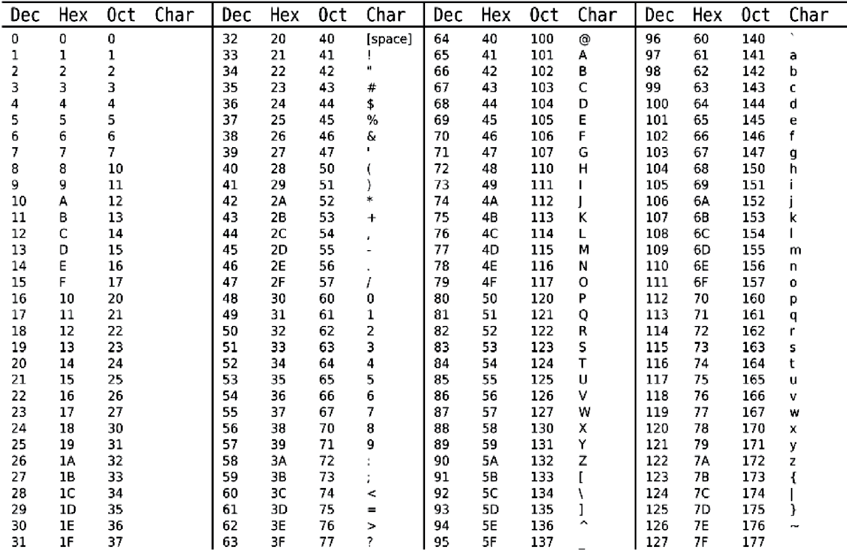
ASCII table. Each character is shown in decimal, hex, and octal. (Courtesy of ZZT32, http://commons.wikimedia.org/wiki/File:Ascii_Table-nocolor.svg .)
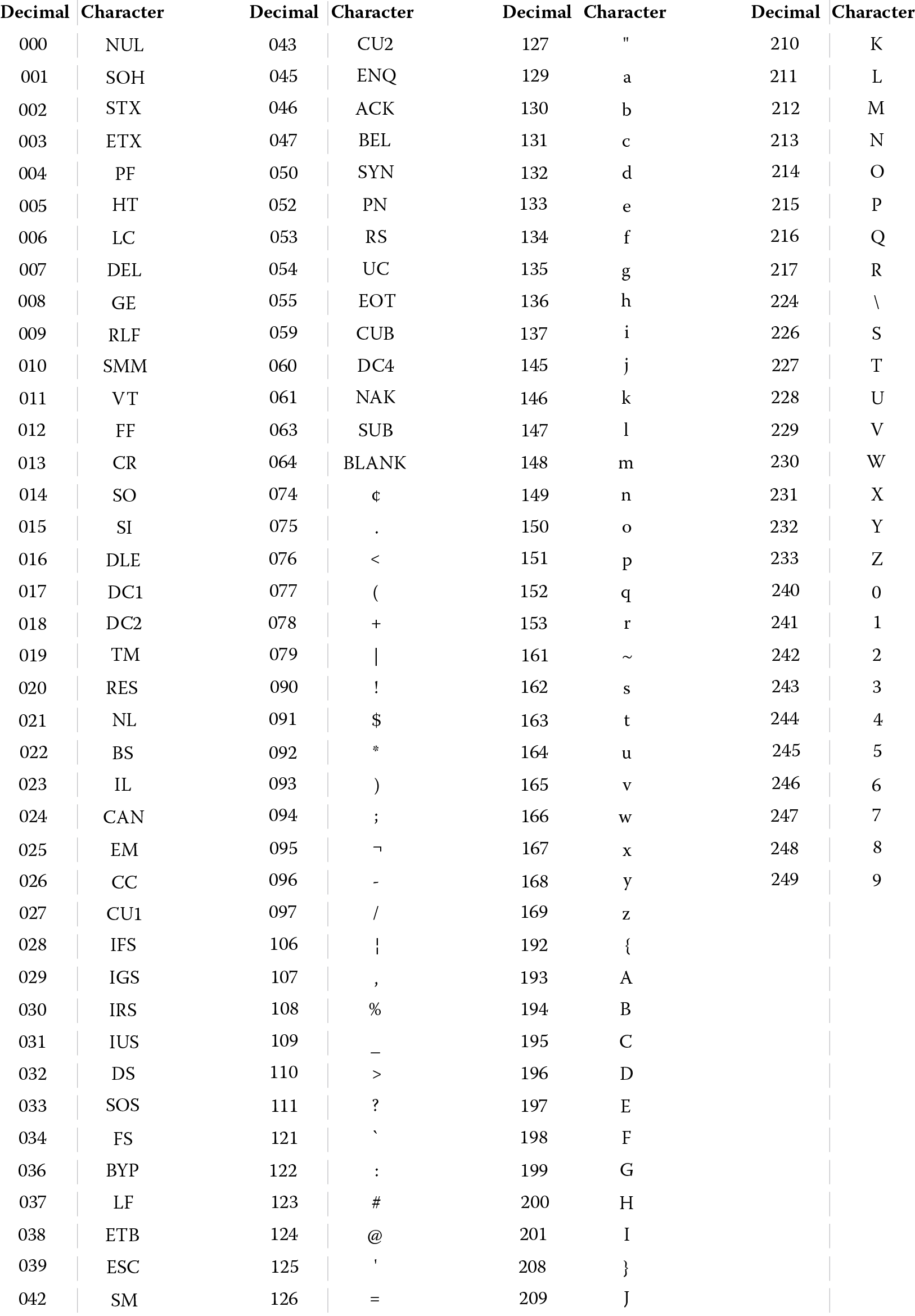
EBCDIC table. (From www.LookupTables.com , http://www.lookuptables.com/ebcdic_scancodes.php . With permission.)
EBCDIC was only used in IBM mainframe computers and was discontinued in part because it was not a very logical representation. If you look over the ASCII representation, you will see that for any two letters, the ASCII representation is in the same cardinal order as the letters appear in the alphabet; so, for instance, ‘a’ immediately precedes ‘b’, which immediately precedes ‘c’, and so forth. The representation is organized so that upper case letters appear before lower case letters. This means that ‘A’ is less than ‘a’ when we compare them. In EBCDIC, although letters are in order (‘a’ before ‘b’ before ‘c’), they do not necessarily immediately follow one another, for instance ‘j’ does not immediately follow ‘i’.
The way ASCII works is that in place of the character, we have the binary sequence. For instance, ‘a’ is stored as the decimal value 97, or the hexadecimal value 61. Using either decimal to binary or hexadecimal to binary, you will see that ‘a’ is 01100001. Compare this to ‘A’, which is decimal 65 (hexadecimal 41), which is 01000001. Interestingly, ‘a’ and ‘A’ are nearly identical, the only difference is with the third bit from the left. The upper case version of every letter has a third bit of 0 and the lower case version of every letter has a third bit of 1.
The ASCII representation uses 7 bits, which gives us 128 different combinations. With the 52 letters, 10 digits, and various punctuation marks, there is room left over for other characters. These include what are known as escape sequences such as the tab key and the return key (or “end of line”). In spite of using 7 bits for ASCII, each ASCII character is stored in 1 byte, so the last bit becomes a 0. This 0 will be inserted as the leading bit (leftmost). The EBCDIC representation uses 8 bits and so contains 256 different combinations.
Let’s consider an example. We want to store the string “Hello”. How is this done? In ASCII, each of the characters is represented by a different code. “H” is 01001000, “e” is 01100101, “l” occurs twice, both times 01101101, and “o” is 01101111. So “Hello” is stored as a sequence of five 8-bit sequences, or five bytes: 01001000 01100101 01101101 01101101 01101111. In EBCDIC, it takes as much storage (five bytes) to store “Hello”, but the representations differ. In EBCDIC, we have instead: 11001000 10000101 10010111 10010111 10010110.
Neither ASCII nor EBCDIC has any representations for letters outside of the English alphabet. With the international nature of computing today, there is a need to represent other languages’ symbols; for instance, the Arabic letters, the Cyrillic letters or Russian, the Chinese and Japanese characters. However, a majority of computer users do speak English. So the decision was made to expand ASCII from 7 bits to 16 bits, which gives us 65,356 different combinations, or the ability to store more than 65,000 characters. This became UNICODE. In UNICODE, the first 128 characters are the same as in ASCII. However, the remainder are used to store the characters found in other languages along with other symbols. These other symbols include the zodiac elements, symbols for chess pieces, the peace sign, the yin/yang symbol, smiley/frowny faces, currency symbols, mathematical symbols, and arrows.
The previous example for “Hello” will look similar in Unicode because the first 128 characters of Unicode are the same as the 128 characters of ASCII. However, in UNICODE, each character is stored in 16 bits rather than 7. So, “Hello” becomes:
0000000001001000 “H”
0000000001100101 “e”
0000000001101101 “l”
0000000001101101 “l”
0000000001101111 “o”
Thus, “Hello” requires twice the storage space in Unicode as it does in either ASCII or EBCDIC. At the end of this chapter, we will find another use for the leading bit in ASCII (the leftmost bit, into which we inserted a 0).
Binary Operations
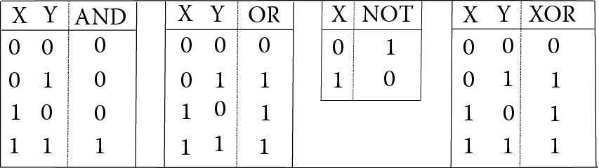
Aside from converting numbers, a computer needs to process values. We typically think of computers performing operations such as addition, subtraction, multiplication, division, and comparison (compare two values to determine if they are equal or which is less than the other). However, the computer operates only on binary values and performs binary operations (these are the same as Boolean operations). The operations are
AND—are the two values both on (1s)?
OR—is either value on (1s)?
NOT—convert the value to its opposite (1 becomes 0, 0 becomes 1)
XOR—exclusive or, are the two values different?
The truth tables for these four basic Boolean operations are shown in Figure 3.5.
Let us consider a few brief examples of applying the binary, or Boolean, operations. First, we will look at simple 1-bit examples.
|
0 OR 0 = 0 |
0 OR 1 = 1 |
1 OR 1 = 1 |
|
0 XOR 0 = 0 |
0 XOR 1 = 1 |
1 XOR 1 = 0 |
|
0 AND 0 = 0 |
0 AND 1 = 0 |
1 AND 1 = 0 |
In essence, we take the two bits and look up the row in the appropriate truth table. For 0 XOR 1, we look at the row where X = 0 and Y = 1.
Even though we apply AND, OR, and XOR to just two bits (and NOT to just 1), it is more interesting and useful to look at larger binary operations. For instance, 11110000 AND 10101010. In this case, we apply the binary operation in a bit-wise fashion. That is, we would apply AND to the first bit of each binary number, and then to the second bit of each binary number, and then…, recording in this case an 8-bit answer because each number is 8 bits long. The operation can be easily performed by lining the two numbers up on two lines, and then applying the operation column by column.
Let us compute 11110000 AND 10101010.
11110000AND1010101010100000
Starting with the leftmost bit, 1 AND 1 is 1. In the next column moving right, 1 AND 0 is 0. Next, 1 AND 1 is 1. Next, 1 AND 0 is 0. Now, notice that the remainder of the bits in the top number as we move right are all 0. 0 AND anything is 0, so the last 4 bits will all be 0.
Let us try XOR, which is slightly more complicated. 10101111 XOR 00111100.
10101111XOR0011110010010011
Here, if the two bits are the same, the result is a 0 and if the two bits differ, the result is 1.
A more complicated series of operations can be applied, for instance, NOT (10110011) AND (11110000 XOR 11001100). First, we will apply the XOR:
11110000XOR1100110000111100
Next, we apply NOT (10110011). This merely flips each bit giving us 01001100. Finally, we apply the AND.
01001100AND0011110000001100
Therefore, NOT (10110011) AND (11110000 XOR 11001100) = 00001100.
You might wonder why we are bothering with such simple operations. At its most basic level, these four operations are all the computer uses to compute with. So we will have to use these four operations to perform such tasks as addition, subtraction, multiplication, division, and comparison. How?
Before answering that question, let us look at how to perform binary addition using our ordinary addition operator, +. Let us do 0111 + 0110. We would accomplish this addition in a similar way to adding two decimal values together. We line them up, we add them column by column in a right-to-left manner, writing down the sum, and if necessary, carrying a unit over to the next column on the left. However, for binary, the only digits we are allowed are 0 and 1, and our carries will be not in units of 10 but units of 2.
Let us now solve 0111 + 0110. The solution is shown in Figure 3.6. We start with the rightmost column. There is no carry in to that column (or more precisely, the carry in is 0). So we want to add 0 (the carry) + 1 + 0 (the rightmost digits of our two numbers). What is 0 + 1 + 0? It is 1. So we write a sum of 1, with no carry over. In the next column, we have 0 (the carry) + 1 + 1. 0 + 1 + 1 is 2. However, we are not allowed to write 2 down as the only digits allowable are 0 and 1. What is 2 in binary? 102. This tells us that we should write down a 0 (the rightmost digit of 102), and carry a 1. Recall that the carry is a power of 2, so we are carrying a unit of 2, not 10. Even so, we write the carry as a 1 digit over the next column. Now in the third-from-right column, we have 1 (the carry) + 1 + 1. This is 3. Again, we cannot write down a 3. But 3 in binary is 112. So we write a 1 and carry a 1. In the leftmost column, we have 1 (the carry) + 0 + 0 = 1. So we write a 1 and have no carry. The carry coming out of the leftmost column can be recorded in the status flags (see Chapter 2) under the carry bit. This may be useful because, if there is a carry out produced, it may be a situation known as an overflow. That is, the two numbers were too large to fit into the destination, so we overflowed the destination (a register or memory).
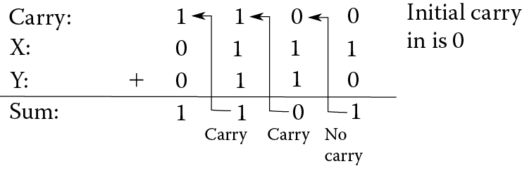
Notice in Figure 3.6 that, for each column, we are computing two things. We compute the sum of the three digits (including the carry in) and the carry out to be taken to the next column as the carry in. We will always add three numbers: the two digits from the number and the carry in. We will always compute two different results, the sum of that column and the carry out. The carry out for one column becomes the carry in for the next column.
The sum algorithm can be expressed as follows:
- Line up the two binary numbers.
- The carry in for the rightmost column is always 0.
- Working right to left, repeat the following, column by column.
- Compute the sum of the two binary digits plus the carry in, as follows:
All three are 0: 0
One of the three is a 1: 1
Two of the three are 1: 0 (1 + 1 + 0 = 2, or 10, sum of 0, carry of 1)
All three are 1: 1 (1 + 1 + 1 = 3, or 11, sum of 1, carry of 1)
- Compute the carry out of the two binary digits plus the carry in, as follows:
All three are 0: 0
One of the three is a 1: 0
Two of the three are 1: 1
All three are 1: 1
- The carry out of this column becomes the carry in of the next column.
- Compute the sum of the two binary digits plus the carry in, as follows:
Let us give it a try. We will add 1001 + 0011. First, we line up the numbers:
1001+ 0001
For the rightmost column, the carry in is a 0. This gives us 0, 1, and 1. According to step 3a above, two 1 bits give a sum of 0. According to step 3b, two 1 bits give us a carry of 1. So we have the following partial result after one column.
Carry:-- 101001+ 0011---0
Now going into the second column (from the right), we have a carry in of 1, and the two digits are 0 and 1, so we have two 1 bits. This gives us a sum of 0 and a carry of 1. Now our partial result is as follows.
Carry:- 1101001+ 0011--00
For the third column, we have a carry in of 1, and two 0 digits. This gives us a sum of 1 and a carry of 0. Now our partial result is as follows:
Carry: 01101001+ 0011−100
Our leftmost column has a carry in of 0 and digits of 1 and 0. This gives us a sum of 1 and a carry of 0. Our resulting sum is then 1100. If we were to convert problem into decimal, we would find that we have just performed 9 + 3 = 12.
Try a few on your own and see how you do.
0001 + 0101 = 0110
1001 + 0011 = 1100
0111 + 0011 = 1010
Now, how do we implement this addition algorithm in the computer since we only have AND, OR, NOT, and XOR operations to apply? We will break our addition algorithm into two computations, computing sum and computing carry. We start with carry because it is a little easier to understand. Recall from above that the carry out is a 1 if either two or all three of the digits are 1. Let us call the three values X, Y, and C (for carry in). There are four possible combinations whereby there are two or three 1s. These are X = 1 and Y = 1, X = 1 and C = 1, Y = 1 and C = 1, or X = 1, Y = 1 and C = 1. In fact, we do not care about the fourth possibility because the three other comparisons would all be true. Therefore, we can determine if the carry out should be a 1 by using the following Boolean logic: (X AND Y) OR (X AND C) OR (Y AND C).
To compute the sum, we want to know if there is either a single 1 out of the three bits (X, Y, C), or three 1s out of the three bits. We can determine this by cleverly chaining together two XORs:
(X XOR Y) XOR C
Let us redo our example from Figure 3.6 using our Boolean operations. The two numbers are 0111 + 0110. Starting with the rightmost column, we have X = 1, Y = 0, C = 0. The sum is (X XOR Y) XOR C = (1 XOR 0) XOR 0 = 1 XOR 0 = 1. So we have a sum of 1. The carry is (X AND Y) OR (X AND C) OR (Y AND C) = (1 AND 0) OR (1 AND 0) OR (0 AND 0) = 0 OR 0 OR 0 = 0. So out of the rightmost column, we have a sum of 1 and a carry of 0.
In the second-to-right column, we have X = 1, Y = 1, C = 0. Our sum is (1 XOR 1) XOR 0 = 0 XOR 0 = 0. Our carry is (1 AND 1) OR (1 AND 0) OR (1 AND 0) = 1 OR 0 OR 0 = 1. So we have a sum of 0 and a carry of 1.
In the third-to-right column, we have X = 1, Y = 1, C = 1. Our sum is (1 XOR 1) XOR 1 = 0 XOR 1 = 1. Our carry is (1 AND 1) OR (1 AND 1) OR (1 AND 1) = 1 OR 1 OR 1 = 1. So we have a sum of 1 and a carry of 1. In our leftmost column, we have X = 0, Y = 0, C = 1. Our sum is (0 XOR 0) XOR 1 = 0 XOR 1 = 1, and our carry is (0 AND 0) OR (0 AND 1) OR (0 AND 1) = 0 OR 0 OR 0 = 0. So our leftmost column has a sum of 1 and carry of 0.
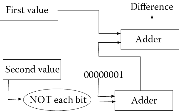
Given two binary numbers, we can perform addition using AND, OR, and XOR. What about subtraction? Let us assume we have two numbers, X and Y, and we want to compute X – Y. You might recall from algebra that X – Y = X + (–Y). Assuming X and Y are two’s complement numbers, we have to modify Y to be –Y. How do we convert a positive number to negative, or negative number to positive, in two’s complement? We flip all of the bits and add 1. How do we flip all of the bits of a number? We use the NOT operation. So in fact, X – Y = X + ((NOT Y) + 1). Thus, subtraction can use the same operations as above for sum and carry, but we add to it a NOT operation first on Y, and then add 1 to NOT Y. We add 1 by again using the sum and carry operations. See Figure 3.7.
Multiplication is a little more complicated, but a multiplication is just a series of additions (x * y requires adding x together y times). Division is a series of subtractions (x/y requires subtracting y from x until we reach 0 or a negative). Therefore, we can apply the addition and subtraction algorithms described above repeatedly to perform multiplication and division. They use a combination of AND, OR, XOR, and NOT.
How about comparison? Actually, this is done very simply. To compare two values X and Y, we do X – Y and see if the result is positive (in which case X > Y), negative (in which case X < Y), or zero (in which case X = Y). To test for negative, look at the leftmost bit of the difference (X – Y); if it is a 1, then the difference is negative (recall in two’s complement, the leftmost bit is the sign), which means that X < Y. To test for zero, OR all of the bits together and see if the result is 0, which means that X – Y = 0 or X = Y. For instance, if we have 00000001, the OR of these bits is 1, so the value is not zero. Positive is actually the most difficult to determine as we have to make sure that the result is not zero and that the leftmost bit is 0. However, we can also determine if a number is positive if it is neither negative nor zero! If the difference is positive, then X – Y > 0 or X > Y.
How do we compare non-numbers? Typically, aside from numbers, the only other things we compare are characters and strings of characters. To see which is greater, “Frank” and “Fred”, we compare character by character until we either reach the end of the string (in which case the strings are equal) or we have a mismatch. Here, we find a mismatch at the third character ‘a’ versus ‘e’. How do we compute ‘a’ – ‘e’? Recall that characters are stored in memory using a representation called ASCII. In ASCII, ‘a’ is 96 and ‘e’ is 100. Therefore to compare “Frank” to “Fred”, we do ‘F’ – ‘F’, which is 0, so we do ‘r’ – ‘r’, which is 0, so we do ‘a’ – ‘e’, which is –4. Since ‘a’ < ‘e’, “Frank” < “Fred”.
A Message from the Stars?
Physicist Frank Drake founded the Search for Extraterrestrial Intelligence (SETI). This effort, started around 1961, was to use radio telescopes (and other forms of observation) to listen for messages from the stars. What form might a message from aliens take? Although we have no idea, it has been proposed that any message would be encoded in some binary representation. Why? Because information is easily transmitted in binary, just send a series of on/off pulses. But what might such a message look like? The aliens should pick a representation that could be easily interpreted. For instance, we would not send out a message in ASCII because ASCII is strictly a human invention and would be meaningless to aliens. To demonstrate how difficult deciphering a message might be, Drake provided the following to his colleagues. Can you figure out what its meaning is? Neither could they!
11110000101001000011001000000010000010100
10000011001011001111000001100001101000000
00100000100001000010001010100001000000000
00000000001000100000000001011000000000000
00000001000111011010110101000000000000000
00001001000011101010101000000000101010101
00000000011101010101110101100000001000000
00000000000100000000000001000100111111000
00111010000010110000011100000001000000000
10000000010000000111110000001011000101110
10000000110010111110101111100010011111001
00000000000111110000001011000111111100000
10000011000001100001000011000000011000101
001000111100101111
Another type of Boolean operation that we will need our computers to perform is known as masks. A mask compares two binary values together using one of AND, OR, or XOR. One use of the AND mask is covered in Examples of Using Binary Numbers.
Examples of Using Binary Numbers
Here, we examine three very different ways that binary numbers are used in computers. In the first, we look at binary numbers as used in network addressing and netmasks. We then look at some common video file representation formats. Finally, we look at the use of binary numbers to perform error detection and correction.
Network Addresses and Netmasks
Computer networks provide a good example of how the binary concepts you have learned so far can be applied. Every computer in a network must have a unique network address. IPv4 (Internet Protocol version 4) addressing uses a dotted decimal format for these addresses. The IPv4 address consists of four numbers, each called an octet. Each number consists of an unsigned 8-bit binary number. Recall that in 8 bits, you can store any decimal number from 0 to 255. So an IP address then is four numbers from 0 to 255, each number separated by a dot (period). For example, your computer’s IP address might be 10.251.136.253. A network address is simply represented as a single 32-bit binary number. We break it down into 4 octets to make it simpler to read.
IP addresses are grouped so that those computers in one network share some of the same octets. This is similar to how street addresses are grouped into zip codes. Computers within a single network can communicate with each other without the need of a router. Routers are used to facilitate communication between networks. This is similar to how post offices are used to facilitate mail delivery between different zip codes. You can tell which street addresses belong to a given post office based on the zip code of that address. Computers have a similar concept. Hidden within your IP address is sort of a zip code that is the address of the network. We refer to this as the network address.
In order to decipher what network address an IP address belongs to, computers use a netmask. Let us look at an example where your IP address is 10.251.136.253, and your netmask is 255.255.255.0. The binary representation (with dots to ease reading) of these numbers is:
|
IP Address: |
00001010.11111011.10001000.11111101 |
|
Netmask: |
11111111.11111111.11111111.00000000 |
To compute the network address, a binary AND operation is performed between these two 32-bit binary numbers resulting in a network address of:
|
Network Address: |
00001010.11111011.10001000.00000000 (10.251.136.0) |
Recall that a binary AND is 1 only if both binary bits are a 1. This netmask has the result of returning the first three octets in their entirety because they are being ANDed with 11111111, with the final octet being masked, or zeroed out, because that octet is being ANDed with 00000000.
In the example above, we use a netmask of 255.255.255.0. This netmask is selected because all computers on this network share the first three octets. That is, the network address is the first three octets of the four octets. Each device’s address on the network is the final octet, thus giving every device a unique address. Now, with a netmask of 255.255.255.0, there are 256 (28) possible addresses in that network. So, this organization would be able to provide 256 unique IP addresses. In dotted decimal format, the network address returned from this operation is 10.251.136.0. This provides network addresses in the range from 10.251.136.0 through 10.251.136.255, including our initial device’s address of 10.251.136.253.
Two computers that share the same network address can communicate with each other without the need of a router. Two computers with different network addresses will know that they need to contact their friendly neighborhood router (often referred to as the default route) in order to communicate between those two devices.
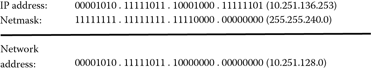
This concept is easy to understand when your netmask aligns evenly with the octet boundaries (i.e., the dots) as it did in our example above. However, let us look at another example where this is not the case. We will use the same IP address, 10.251.136.253, but with a netmask of 255.255.240.0. To compute our network address, we perform a binary AND of these two numbers. Figure 3.8 demonstrates the application of the netmask 255.255.240.0, where our network address turns out to be 10.251.128.0 rather than 10.251.136.0.
Netmasks are determined by the number of bits in the address that make up the network portion of the address. Some network addresses only comprise the first octet. For instance, one network may be 95.0.0.0 (or 01011111.00000000.00000000.00000000). This network would use a netmask of 255.0.0.0.
Obviously, understanding binary numbers and their operations is very important to those studying networking. Networking professionals must be fluent in understanding Boolean operations of AND, OR, NOT, and XOR. We cover networks in detail in Chapter 12.
Image Files
Earlier in this chapter, we saw that numbers (positive, negative, integer, fractional) can all be stored in binary either directly or through a representation such as two’s complement or floating point. We also saw that characters are represented in binary using a code called ASCII. How are images stored in a computer? The most straightforward format is known as a bitmap. We will first consider a black and white image.
Any image is a collection of points of light. Each individual point is known as a pixel (short for picture element). For a black and white image, a pixel will take on one of two colors, black or white. We can represent these two colors using 1s and 0s (commonly, white is 1 and black is 0). To store a black and white image is merely a matter of placing into the file each pixel, row after row. The image in Figure 3.9 is a simple bitmap. The figure contains both the image and the storage in binary (to the right of the image).
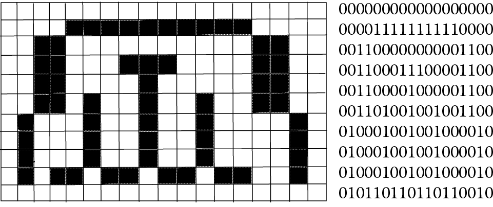
For a black and white image of X × Y pixels (X rows, Y columns), the storage required is X * Y bits. A 1000 × 1000 pixel image requires 1,000,000 bits. This would be 125,000 bytes, or roughly 125 KB.
A variation of a black and white image is a gray scale image. Here, different shades of gray are added to the strictly black and white image. To represent an image, similar to the black and white image, each pixel is stored as one value, but now the value is in a range from least intensity (black) to most intensity (white). Any value in between is a shade of grey. Most commonly, the level of intensity will be an integer number from 0 to 255, so that each pixel can be stored in 1 byte. A 1000 × 1000 pixel image would require 1,000,000 bytes (roughly 1 MB). This is 8 times the size of the black and white image, which makes sense because we increased the storage requirement from 1 bit per pixel to 1 byte per pixel.
Colors are represented in the computer by the amount of red, green, and blue that make up that pixel’s light. We refer to this strategy as RGB. For a color image, we would store each pixel as a trio of numbers, the amount of red, the amount of green, and the amount of blue. As with gray scale images, we will store each of these intensities as an integer in 1 byte, giving us a range of 0–255. The color represented by (0, 0, 0)—that is, no red, no green, no blue—is black. The color represented by (255, 255, 255) is white. The color represented by (255, 0, 255) is purple (full red, no green, full blue). In binary, purple would be indicated as the three numbers (11111111, 00000000, 11111111). For convenience, we often denote RGB values in hexadecimal instead. So purple is FF00FF. This notation is used in designing web pages. Yellow, for instance, is all green and all blue with no red, or (0, 255, 255), or 00FFFF. The value 884400 would be (128, 64, 00), that is, it would be half of red and one fourth of green, a brownish-orange color.
For RGB, a 1000 × 1000 pixel image would require 3,000,000 bytes or roughly 3 MB. Note that using RGB as a representation, every pixel in an image can be one of more than 16 million colors (256 * 256 * 256).
As you can see, going from black and white to color greatly increases the file size. Are there any ways to reduce file sizes of images? Yes, by file compression. The two most common forms of compression are GIF and JPG. GIF stands for Graphics Interchange Format. The idea is that humans generally cannot differentiate between the millions of colors available in any kind of precise way. Why use so much storage space when one shade of red might look like another? In GIF, a color palette is provided that consists of 256 of the most popular colors. This permits each pixel to reference a color in the palette using only 1 byte instead of the 3 bytes (required for RGB); therefore, the size of the color image is reduced by a factor of 3. The 1000 × 1000 pixel color image now requires only 1 MB of storage. Unfortunately, if the original image uses colors that are not a part of the standard palette, then the image will look different, and in some cases you will get a very improper replacement color, for instance, blue in place of a pale yellow.
The JPG format is perhaps more common than GIF. JPG stands for Joint Photographic Experts Group (the original abbreviation for a JPG file was .jpeg). In GIF, if the colors are available on the palette, the resulting GIF file looks identical to the BMP file and is therefore known as lossless compression. But JPG uses lossy compression. The difference is that after compressing the image, some quality is lost. You sacrifice image quality for storage size. The JPG compression format works by combining some of the pixels together into blockier groups of pixels. In effect, the image loses some resolution and becomes blurrier. In addition, if the image is a color image, it is translated from RGB to an alternative color format known as YUV, where each pixel is represented using brightness (Y) and luminescence (U and V). This format requires either two times or four times less storage space than RGB. Additionally, the lossy compression in the JPG format can reduce the image size even more so.
The newer PNG (Portable Network Graphics) enhances the GIF format. Like GIF, it is a lossless form of compression that uses a bitmap. It can support a 24-bit RGB palette, gray scale, and bitmaps without palettes. And like JPG, it compresses images to reduce space, but using a lossless algorithm so that the compressed image is of equal quality. Unlike JPG, the PNG compression may or may not succeed in truly reducing file size.
Error Detection and Correction
One significant challenge when dealing with computer-stored information is handling errors that arise during transmission of data from one location to another. It is unlikely but possible for errors to occur when data are moved from one component to another in the computer, but it is far more likely and even expected that errors can arise during transmission. Therefore, some form of error detection and correction is desired.
The simplest form of error detection is through the use of parity. In general, parity means equality. But when discussing a computer, parity refers to the evenness (or oddness) of a number. Specifically, we will count the number of 1 bits in a sequence of data and see if that count is even or odd. We can then use this to detect simple errors in transmission.
We will introduce a parity bit to every byte (8 bits) of storage. The parity bit will be 1 if the number of 1 bits in the byte is odd, and the parity bit will be 0 if the number of 1 bits in the byte is even. That is, the 8 bits plus the parity bit should always have an even number of 1 bits. This strategy is known as even parity (there is a variation called odd parity where the 8 bits plus parity bit must always have an odd number of 1 bits).
We will use even parity as follows. Given a byte, before this datum is moved, we will generate a parity bit. Now we have 9 bits. We transmit/move the 9 bits. The recipient receives 9 bits. If the 9 bits has even parity, then no error occurred. If the 9 bits has odd parity, an error occurred, the datum is discarded, and the recipient requests that the datum be resent.
How can we determine even or odd parity? It is very easy just using the XOR operation (refer back to Figure 3.5). The XOR operation only operates on 2 bits at a time, but we can chain together the XOR operations. So, given 8 bits, we XOR the first two bits and then XOR the result with the third bit and then XOR the result with the fourth bit, and so forth. Let us look at some examples of computing and using the parity bit. We want to move a datum 10010011 to another location in the computer or over a network. The first step is to compute the parity bit:
(((((((1 XOR 0) XOR 0) XOR 1) XOR 0) XOR 0) XOR 1) XOR 1) =
((((((1 XOR 0) XOR 1) XOR 0) XOR 0) XOR 1) XOR 1) =
((((((1 XOR 1) XOR 0) XOR 0) XOR 1) XOR 1) =
((((0 XOR 0) XOR 0) XOR 1) XOR 1) =
(((0 XOR 0) XOR 1) XOR 1) =
((0 XOR 1) XOR 1) =
(1 XOR 1) = 0
Therefore, 10010011 has a parity bit of 0. This makes sense because the total number of 1 bits should be even. 10010011 has four 1 bits, and so to keep the number of 1 bits even, we add a 0. Now, the 9 bits consist of four 1s and five 0s.*
We transmit these 9 bits and the recipient receives 10010011 & 0. The recipient performs a similar operation, XORing all 9 bits together, and winds up with 0. Therefore, it is correct, that is, no error arose.
Now consider if, upon receipt, the 9 bits were 10010011 & 1. In this case, the XOR computes:
((((((((1 XOR 0) XOR 0) XOR 1) XOR 0) XOR 0) XOR 1) XOR 1) XOR 1) = 1
So an error arose. Where did the error arise? By using a single parity bit, we do not know, but because there is an error, the recipient discards the data and asks for it to be re-sent. Notice in this case that the error arose in the parity bit itself. Another example might be 10010010 & 0, where the parity bit has no error but the byte has an error (the last bit should be 1). The recipient computes the XOR of these 9 bits and gets
((((((((1 XOR 0) XOR 0) XOR 1) XOR 0) XOR 0) XOR 1) XOR 0) XOR 0) = 1
Notice that the parity bit not only does not help us identify the error, but would also fail us if two errors arose. Imagine that the recipient gets 10010000 & 0. In this case, the last 2 bits are incorrect. If we XOR these 9 bits, we get 0, implying that no error occurred. Thus, the parity bit can detect 1 error but not 2, and cannot correct the error. If we want to correct the error, we would need more than 1 parity bit.
Also, the parity bit does not necessarily have to be associated with a byte. Recall from earlier in this chapter that ASCII values use 7 bits of a byte. The eighth bit can be used to store parity information. For instance, the letter ‘a’ is represented as x1100001. The initial x is unused, so we would normally place a 0 there. However, rather than waste the bit, we can put a parity bit there. So, in fact, ‘a’ will be stored as 11100001 if we wish to include a parity bit. This saves us from having to add yet another bit.
Another use of parity comes with RAID technology. RAID is a newer form of disk storage device where there are multiple disk drives in one cabinet. The idea is that extra disk drives can provide both redundant storage of data and the ability to access multiple drives simultaneously to speed up disk access. RAID is discussed in more detail in Chapter 15 (Information Assurance and Security). Here, we briefly look at how parity can be used to provide error correction.
Imagine that we have five disk drive units. We will store 4 bytes of data on four different drives. The fifth drive will store parity information of the 4 bytes. For each 4-byte grouping that is distributed across the disks, we will also compute parity information and store it on the fifth drive. Consider one 4-byte group of data as follows:
|
11001111 |
01010101 |
11011011 |
00000011 |
We will compute bit-wise XOR across each of the 4 bytes. This means that we will take the first bits (leftmost bits) of the 4 bytes and compute XOR of those 4 bits. This will be the parity bit for the first bit of the four bytes. We will do this for each bit of the 4 bytes.
|
11001111 |
//first byte, stored on the first disk |
|
|
XOR |
01010101 |
//second byte, stored on the second disk |
|
XOR |
11011011 |
//third byte, stored on the third disk |
|
XOR |
00000011 |
//fourth byte, stored on the fourth disk |
To obtain the parity information then, we compute each XOR going down. The first parity bit is (((1 XOR 0) XOR 1) XOR 0) = 0. The second parity bit is computed as (((1 XOR 1) XOR 1) XOR 0) = 1. The third parity bit is computed as (((0 XOR 0) XOR 0) XOR 0) = 0. The fourth parity bit is computed as (((0 XOR 1) XOR 1) XOR 0) = 0. The fifth parity bit is computed as (((1 XOR 0) XOR 1) XOR 0) = 0. The sixth parity bit is computed as (((1 XOR 0) XOR 0) XOR 1) = 0. The seventh parity bit is computed as (((1 XOR 0) XOR 1) XOR 1) = 1. The eight parity bit is computed as (((1 XOR 1) XOR 1) XOR 1) = 0. So, our parity byte is 01000010. This byte is stored on the fifth disk.
Now, let us assume over time that the second disk drive fails—perhaps there is a bad sector, or perhaps the entire disk surface is damaged. Whatever the case, we can restore all of the data by using the three other data drives and the parity drive. For our 4 bytes above, we would have the following data available:
|
11001111 |
//first byte, stored on the first disk |
|
xxxxxxxx |
//second byte data is damaged |
|
11011011 |
//third byte, stored on the third disk |
|
00000011 |
//fourth byte, stored on the fourth disk |
|
01000010 |
//parity byte, stored on the fifth disk |
We XOR the four corresponding bits of the three bytes plus parity byte to obtain the missing data. For instance, using the first bits of each byte, we have (((1 XOR 1) XOR 0) XOR 0) = 0. So the first bit of our missing datum is 0. The second bit would be (((1 XOR 1) XOR 0) XOR 1) = 1. See if you can work through the remainder of this example to obtain the entire missing datum.
Using a single parity bit per byte is sometimes referred to as a horizontal redundancy check because the parity bit is computed across a block of data. Another form of horizontal redundancy check is a checksum (briefly mentioned in Chapter 12). The parity computation used for RAID is sometimes referred to as a vertical redundancy check because the parity computation is performed across a number of bytes, bit by bit.
Further Reading
A study of binary representations can be found in nearly every computer organization book (See the section Computer Hardware and Computer Assembly (Installation) in Chapter 2). The Kindle text, Binary Made Simple (R. Barton) available from Amazon Digital Services offers a useful look at how to perform conversions between binary, decimal, and hexadecimal. More thorough books on numbering systems provide background on theory and computation, such as the following:
- Conway, J. The Book of Numbers, New York: Springer, 1995.
- Guilberg, J. and Hilton, P. Mathematics: From the Birth of Numbers, New York: Norton, 1997.
- Ifrah, G. The Universal History of Numbers: From Prehistory to the Invention of the Computer. New York: Wiley, 1999.
- Niven, I., Zuckerman, H., and Montgomery, H. An Introduction to the Theory of Numbers, New York: Wiley, 1991.
Boolean (binary) operations and logic are also covered in computer organization texts. You can also find whole texts on the topic. A few choice texts are listed here.
- Brown, F. Boolean Reasoning: The Logic of Boolean Equations. New York: Dover, 2012.
- Gregg, J. Ones and Zeros: Understanding Boolean Algebra, Digital Circuits, and the Logic of Sets. Piscataway, NJ: Wiley-IEEE Press, 1998.
- Whitesitt, J. Boolean Algebra and Its Applications. New York: Dover, 2010.
As Chapter 12 covers computer networks in detail, see that chapter for further readings for information on such things as IP addresses and netmasks.
A comprehensive reference on the major forms of computer graphics files is available:
- Miano, J., Compressed Image File Formats: JPEG, PNG, GIF, XBM, BMP. Reading, MA: Addison Wesley, 1999.
These formats are all stored as binary files, which we discuss in Chapter 5.
Review Terms
Terminology introduced in this chapter:
ASCII Mantissa
Base Netmask
Binary Numbering systems
Bit Octal
Bitmap Octet
Byte Parity
Compression Parity bit
Decimal Pixel
EBCDIC PNG
Floating point RAID
GIF Two’s complement
Hexadecimal Unicode
JPG Word
Lossy compression
Sample Problems
- Convert 10111100 from binary to decimal.
- Convert 10111100 from two’s complement binary to decimal.
- Convert 10100011 in two’s complement to its negation (i.e., change its sign).
- Repeat #3 for the two’s complement binary value 00010010.
- Convert 43 from decimal to 8-bit binary.
- Convert –43 from decimal to two’s complement 8-bit binary.
- Convert F3EA116 to binary.
- Convert 317528 to binary.
- Convert 876 from decimal to octal.
- Convert 6732 from decimal to hexadecimal.
- Convert –45.625 from decimal to the 16-bit floating point representation of the chapter.
- Convert 0111001100110000 from the 16-bit floating point representation of the chapter into decimal.
- What is 10011110 AND 00001111?
- What is 10011110 OR 00001111?
- What is 10011110 XOR 00001111?
- What is NOT 10011110?
- Perform the 8-bit addition: 00110011 + 01010101
- Perform the 8-bit addition: 01111011 + 00111110
- Perform the 8-bit subtraction: 01010101 – 00001111 (hint: convert the second number to its two’s complement opposite and then perform addition, the result will produce a carry out of the leftmost column, ignore it)
- How many bytes would it take to store the following text using ASCII?
Holy cow! The brown fowl jumped over the moon?
- Repeat #20 in Unicode.
- What is the parity bit of 11110010?
- Repeat #22 for 11110011.
- Repeat #22 for 00000000.
- Given the byte 10011101 and the parity bit 1, assuming even parity, is there an error?
- Repeat 25 for the byte 11110001 and the parity bit 0.
- Compute the value ((((1 XOR 0) XOR 1) XOR 1).
- Given the four bytes 00000000, 00000001, 11110000, and 10101101, compute the parity byte.
Review Questions
- In your own words, what does NOT do?
- In your own words, explain when the AND operation will be true.
- In your own words, explain when the OR operation will be false.
- In your own words, explain when the XOR operation will be false.
- How does XOR differ from OR?
- Why is binary of importance to our society? Why is it important for you to understand binary in information technology?
- What is a mantissa? What is a base?
- What is lossy compression?
- Explain why a 1024 × 1024 pixel color bitmap requires 3 MB of storage space.
- Explain how a jpg image is able to reduce the storage space required of the same bmp file.
- Why do you suppose we do not use EBCDIC as our preferred form of character representation?
- What is an octet?
- What is the difference between even parity and odd parity?
Discussion Questions
- Is it important for an IT person to understand the binary numbering system? Aside from the examples covered in this chapter (ASCII/Unicode, bitmaps, netmasks), attempt to identify five other reasons why knowledge of binary may come in handy in IT.
- Where might you find hexadecimal notation in use? Provide some examples.
- Provide several examples of how or why you might need to apply Boolean operators (AND, OR, NOT, XOR).
- Does the fact that computers use binary to store information make it more challenging to understand how computers work? If so, in what way(s)?
- Compression has become an increasingly important part of computing because of multimedia files—moving such files across the Internet (e.g., downloading, streaming) and storing files on your computer. Examine the various forms of audio and video compression. What are the issues that might help you choose a form of audio compression to stream a song? To permanently store a song? What are the issues that might help you choose a form of video compression to stream a video? To permanently store a video?
- Examine Frank Drake’s “message from the stars” in the sidebar of this chapter. Attempt to locate meaningful units of information. For instance, is there a binary code that is used for “start” and “stop” tags to indicate word, phrase, or concept boundaries? Can you identify any patterns in the bits?
- Research typical error rates in telecommunications (i.e., how many errors typically arise when transmitting say 1 million bits). Given this error rate, how likely is it to find two errors in any single byte transmission?
- Two other forms of error detection and correction are checksums and Hamming distance codes. Briefly research these and describe them. How do they differ from the use of the parity bit? Which would of the three would be the best way to detect errors in telecommunications?
- Devise your own message from the stars. What would you want to say to another species that indicates that you are intelligent and wish to communicate with them?
* Computing parity can be done much more simply than applying the XOR operation; just add up the number of 1 bits and make sure that the bits in the datum plus the parity bit is always an even number.