
Chapter 12
Networks, Network Software, and the Internet
In this chapter, computer networking is covered. This chapter begins by describing the computer hardware that makes up the physical components of a computer network. Next, networks are discussed at an architectural level: classifications of networks and network protocols. Network software, including specific Linux software, is covered. Finally, the chapter examines the Internet: what makes it work, how it has grown, and what its future may be.
The learning objectives of this chapter are to
- Describe the role of network broadcast devices.
- Differentiate between types of network media.
- Compare network topologies and classifications.
- Discuss the role of each layer in the TCP/IP protocol stack and the OSI model.
- Explain IPv4 addressing and compare it to IPv6.
- Introduce popular forms of network software.
- Present a brief history of the Internet.
- Describe how communication takes place over the Internet.
A computer network is a collection of computers and computer resources (e.g., printers, file servers) connected in such a way that the computers can communicate with each other and their resources. Through computer networks, people can communicate, share data, share hardware, isolate and secure data, and provide a platform for easy data backup. Networks (particularly the Internet) also offer a means for commerce and sales. In fact, there are a number of different benefits that the Internet has provided.
Although networks are known to improve workplace efficiency through the sharing of data, resources, and communication, there are a number of costs associated with any computer network. There is the cost to purchase and set up the physical media and administer the network. However, that is not nearly the concern as the cost of securing the network properly, or the cost of having an insecure network. Additionally, through computer networks, most people have access to the Internet, and in a workplace, this could lead to undesirable behavior and inefficient use of time. Some of the threats to a computer network and activities required in securing a computer network are covered in Chapter 15.
Although a network can consist of many types of resources, it is the computer that is the primary tool used to communicate over a network. In a network, we define computers as being local or remote. A local computer is the computer that the user is using. That is, the user is physically present with that computer. A remote computer is a computer being accessed over the network. For instance, using a remote desktop connection or telnet [or ssh (secure shell)], you can log in to another computer. The computer you are logging into is referred to as the remote computer. A host is a type of computer that can be logged into from a remote location. This used to be an important distinction in that many personal computers could not be host computers. But today, that is not necessarily the case as most computers permit some form of remote login or remote desktop connection.
Computer networks can be viewed at a physical level (the connections or physical media over which communication is possible), a logical level (network topology), or a software level (the protocols and programs that allow the computers to communicate). This chapter examines some of the ideas behind computer networks at each of these levels.
Networks at a Hardware Level
The physical level of a network defines how information is carried over the network. At this level, information is transmitted as bits over some type of media—a physical connection. The media transmits information as electrical current, electromagnetic waves, light pulses, or radio waves (sometimes at ultrahigh frequencies such as microwaves). The form of transmission is based on the type of media selected. The type of media is selected, at least in part, based on the distance between the resources on the network. The form of media also dictates to some extent the network’s bandwidth. The bandwidth is the transfer rate permissible over the media, described as some number of bits per second (bps or b/s). Modern bandwidths are on the order of millions of bits per second (Mbits/second, Mbps). Older technologies such as computer MODEMs (described later) were limited to hundreds or thousands of bits per second, such as 56 Kbps.
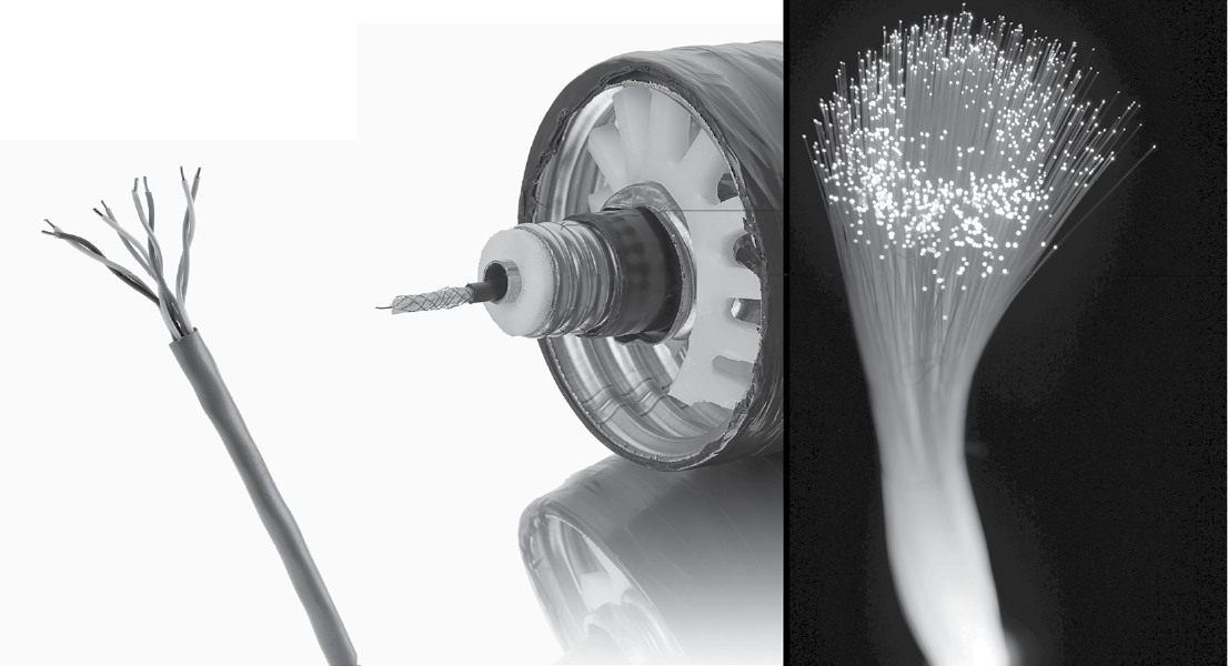
The most common form of network connection used today is coaxial cable and fiber optic cable. In the past, the most common connection was through twisted wire pair, as used in much of the United States telephone network. We still find twisted wire pair used extensively because it is cheap and because so much of it is already in place. Both coaxial cable and twisted wire transmit information using electromagnetic waves, whereas fiber optic cable uses light pulses. For long distances, cable is too expensive, and so radio signals are sent via radio towers, cell phone towers, microwave towers, and bounced off of satellites in orbit. See Figure 12.1 for a comparison of twisted wire pair (four in one cable in this figure), a coaxial cable, and dozens of strands of fiber optic cable.
At this physical level, the network is responsible for encoding or decoding the data into signals, modulating and demodulation signals, transmitting and receiving signals, and routing of signals. Transmission is the last step that the network performs when sending a message, and reception is the first step when receiving a message. Encoding/decoding requires translating the individual bits in the message from the form stored in the computer to the form that the network requires. The message, as stored in computer memory, consists of electrical charges (current) whereas when transmitted over fiber optic cable, the message will be a series of light pulses. If the physical media carries an analog signal rather than a digital signal, further translation is needed, known as modulation. When the signal is carried over the telephone line, a sequence of 1s and 0s is translated into a tone, to be broadcast. Demodulation translates from an analog signal to the original digital signal. Finally, routing steers the message from one network location to the next.
The form of routing depends on whether the network is packet switched or circuit switched. A circuit switched network requires that a full pathway, or circuit, be established before transmission can begin and maintained during the entire transmission. The telephone network is a circuit switched network. Because the path exists during the entire conversation, communication in either direction can occur simultaneously. In a packet switched network, a message’s pathway is only established as it is sent. When a message is received at one location, if it is not the destination location, then the message is forwarded on to another location. The choice of pathway is based on network availability and amount of message traffic. Most computer networks are packet switched, with the Internet being the most well-known and commonly cited example. Figure 12.2 illustrates a network where the message is routed from location to location until it arrives at its destination. If the network was circuit switched, the route would be established in advance. If the network was packet switched, the route would be established one branch at a time. Thus, in packet switching, several messages between the same two resources could cross the network using different paths.

Aside from the physical media that connects the network resources together, there are other devices used to broadcast messages from one location to another. The broadcast devices consist of hubs, switches, routers, and gateways. Collectively, these devices “glue” the network together by providing points where a network can connect to devices and to other networks.
A network hub is merely a device that connects multiple computers together. When there are multiple computers connected to a hub, a message received by the hub is made available to all computers in the hub. A destination address attached to the message indicates which computer the message is intended for, but it does not necessarily prevent other computers from picking up the message. A network switch is a more capable connection than a hub. For one, it records the local network addresses [Media Access Control (MAC) addresses] of all computers connected to the switch. A message is then only passed along to the computer that matches the destination address. Thus, the switch is able to utilize network bandwidth more efficiently.
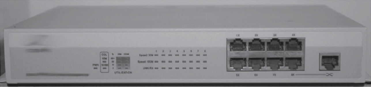
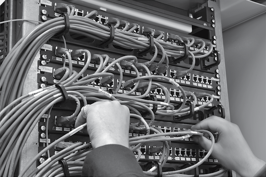
The router is a device that connects multiple networks together. Therefore, the router is like a switch for switches. Although you can use a router to directly connect computers in a network, routers are typically used instead in specific locations in a network so that messages can be routed to other networks. Figure 12.3 is a network hub and Figure 12.4 demonstrates several network switches with devices attached. Externally, there is little to differentiate a hub from a switch from a router (other than perhaps the size). Internally, the switch has more hardware, including storage space for MAC addresses, than a hub. A router contains programmable routing tables and includes at least one input that comes from another network.
The switch and router use the message’s destination address to select the line to route the incoming message to. A router has additional decision-making capabilities. For instance, if message traffic exceeds its capacity, the router may have to purposefully drop messages. Additionally, when there are multiple incoming messages, the router must select which to forward first. A routing decision is the destination network that a message is placed onto. This decision is generally left up to a routing table stored in the router’s memory.
The network gateway is a router that connects networks of different types. That is, if there are two networks that use different protocols, the gateway is not only capable of routing messages from one network to the other but also of handling the differences in the messages themselves because of the different protocols (we discuss protocols in Networks at a Logical Level). Gateways appear at the edge of a network because they connect different types of networks. Gateways, unlike routers, switches, and hubs, are not core components within a network. For this reason, gateways may also serve as firewalls.
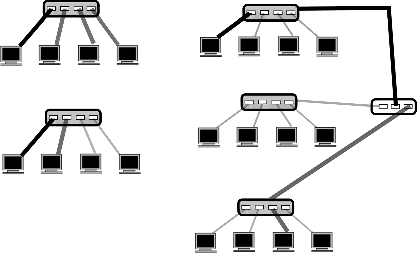
Figure 12.5 illustrates how these four broadcast devices differ. The hub merely passes any message to all devices, thus it is a shared communication (whether that was intended or not). This is shown in the top-left portion of Figure 12.5, where the first (leftmost) computer sends a message to the hub, which is then distributed to the remaining computers. On the other hand, the switch, shown in the bottom-left portion of Figure 12.5, passes a message on to only one destination device, so the communication is dedicated. The router, shown in the right side of Figure 12.5 connects local area networks together so that one hub or switch can be connected to another. In the figure, the second from the right computer in the top network is sending a message to the leftmost computer in the bottom network. In general, a router uses the message’s destination address to determine which network to route the message onto. The gateway, which would also look like that shown in the right-hand side of Figure 12.5, serves the same purpose as the router except that it can convert from one protocol to another while passing a message from one network to another. The gateway then is used to connect different types of networks together, whereas the router connects networks of the same type (protocol) together.
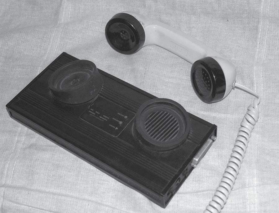
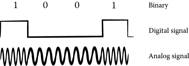
Aside from communication over computer networks, users can communicate via the telephone system. In fact, this was the most common means of telecommunications for decades. The telephone network is set up to pass signals in an analog form over twisted wire pair. Computer data are stored in a binary form, either as electrical current internally or magnetic charges stored on disk or tape. The binary data must first be converted into an analog form. This requires modulation (a digital-to-analog conversion). See Figure 12.6, where the sequence 1001 (or high, low, low, high current) must be translated into analog form, or a sound, in which the wave forms are closer together to represent 1s and further apart for 0s, which is heard by the human ear as different tones. In this form, the data can be transmitted over the telephone lines. The receiving device must convert the analog signal back into a digital form. This is demodulation (analog-to-digital conversion). A MODEM is a device that performs MOdulation and DEModulation. A user would connect the MODEM to the telephone line (for instance, a telephone wall jack), then place a phone call to a destination that also has a MODEM. Next, the telephone handset would be inserted into a MODEM cradle, as shown in Figure 12.7. The computers at both ends can now communicate with each other. After communication, the handset would be placed back on the telephone to end the phone call. Today, MODEMs are built into the computer so that you can plug your computer directly into the telephone wall jack although more commonly, a wireless card lets your computer communicate to your wireless MODEM, which can be placed at nearly any point in the house.
Networks at a Logical Level
There are many ways that the computer resources can be connected together in a computer network. The various layouts are collectively called network topologies. The topology chosen dictates the cost of the network as well as the amount of time it might take for a message to be routed to the destination. In addition, the topology can impact the reliability of the network. Figure 12.8 demonstrates a variety of different topologies. In the figure, computers and computer resources (file servers, printers, hubs, switches, routers, CD ROM towers, tape drives, etc.) are all denoted as circles. The lines that link the nodes together are the connections in the network, typically made up of some sort of cable (as shown in Figure 12.1, this could be twisted wire pair, coaxial cable, fiber optic cable, or some combination of these options). The various topologies are a bus topology (upper left), star topology (middle left), ring topology (to the right of the star), full mesh (lower left), and nearest neighbor topologies on the right side of the figure [one dimensional (1-D), 2-D, tree, 3-D]. Not shown in the figure is a 4-D topology known as a hypercube.
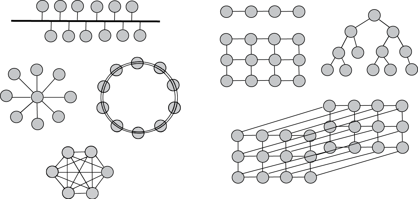
The simplest form of a network is a point-to-point network where there is a dedicated link between two resources. As a network topology, point-to-point is not often used because it limits how devices can communicate with each other. We do see point-to-point connections within a computer such as the bus connecting the ALU to registers in the CPU, or the connection between the monitor and the motherboard). We may also see point-to-point networks in the form of long distance connections such as dedicated telephone lines between two locations (e.g., the famous red phone that connects the White House and the Kremlin).
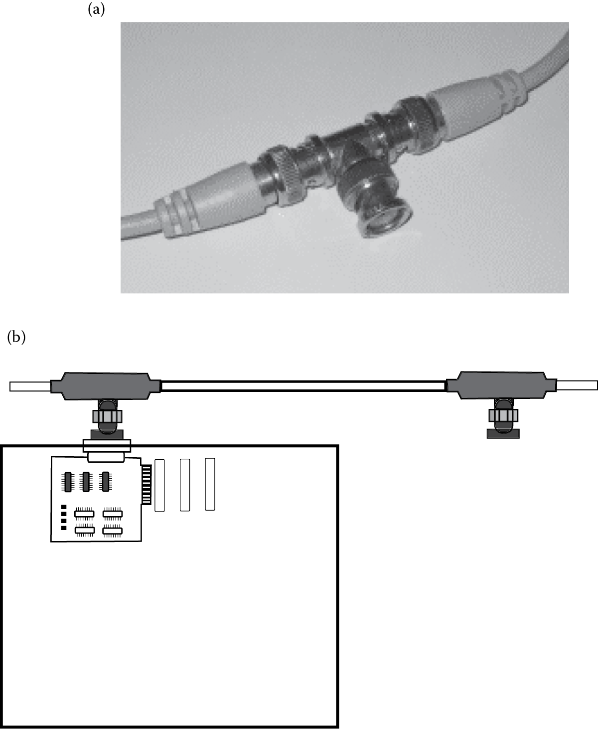
The bus network topology is the next simplest form and is very common. In this topology, every resource is connected to a single cable. The cable is the network, and it carries one message at a time. Devices connect to the bus through “T” connections. Each device would plug into a “T” connector that would plug into two cables, each leading to the next device and “T” connector. Each end of the network would be connected to a terminator. A cable will have a limited number of “T” connections however, so that the size of the network is restricted. Figure 12.9 shows a “T” connector and Figure 12.9 shows how computers connect to “T” connectors through network cards. A network card is plugged into an expansion slot on the motherboard of the computer. The “T” connector is slotted into a port so that it sticks out of the back of the system unit.
Another means to connect devices to the single network is through a hub or switch. In this case, devices plug into the single connection through the back of the hub or switch. If a network needs expansion, hubs or switches can be daisy chained together.
In the bus network, all devices listen to any communications over the single cable and ignore all messages that are not intended for them. The bus provides a dynamic network in that devices can be added and removed from the network at any time as long as there are still “T” connectors available.
The bus network is the cheapest of all network topologies. It is a reliable form of network and it does not degrade if a resource is either removed from the network or crashes. We will see that other forms of networks can degrade when a resource crashes. In spite of this, the bus network topology has a large drawback. All messages travel along the single cable and so the network’s efficiency degrades as more devices are connected to it. The greater the number of devices connected to it, the greater the demand will be on the network. This, in turn, creates greater message traffic. So, the likelihood of two devices needing to use the network at the same time increases as we add devices to the network.
What happens if two devices try to communicate at the same time? This is known as message contention, and the result is that the messages will interfere with each other. Therefore, after contention is detected, at least one of the devices must wait while another device reattempts the communication. A strategy for handling message contention is discussed later in this chapter, developed for Ethernet technology.
The star network is in some ways the antithesis of the bus network. In the star network, all devices have a single point-to-point connection with a central server. This server is a device dedicated to act as a communication hub, routing messages from one machine to the destination. The advantages of the star network are its simplicity, ease of adding (or removing) devices, and the efficiency of message transferal. The star network does not have to contend with message traffic like the bus network (although the hub can quickly become a bottleneck if there are a lot of simultaneous messages). The number of links that it takes for any message to reach its destination is always two (or one if the message is intended for the hub device).
The star network has two detractors. First, it does require a dedicated device, making it a more expensive network than the bus. The hub of the star network may be a hub or switch as discussed in Networks at a Hardware Level. The hub of the star network may also be a server, which would make the star network more expensive. Second, although losing any single device would not degrade the network, if the hub is lost, all devices lose connectivity.
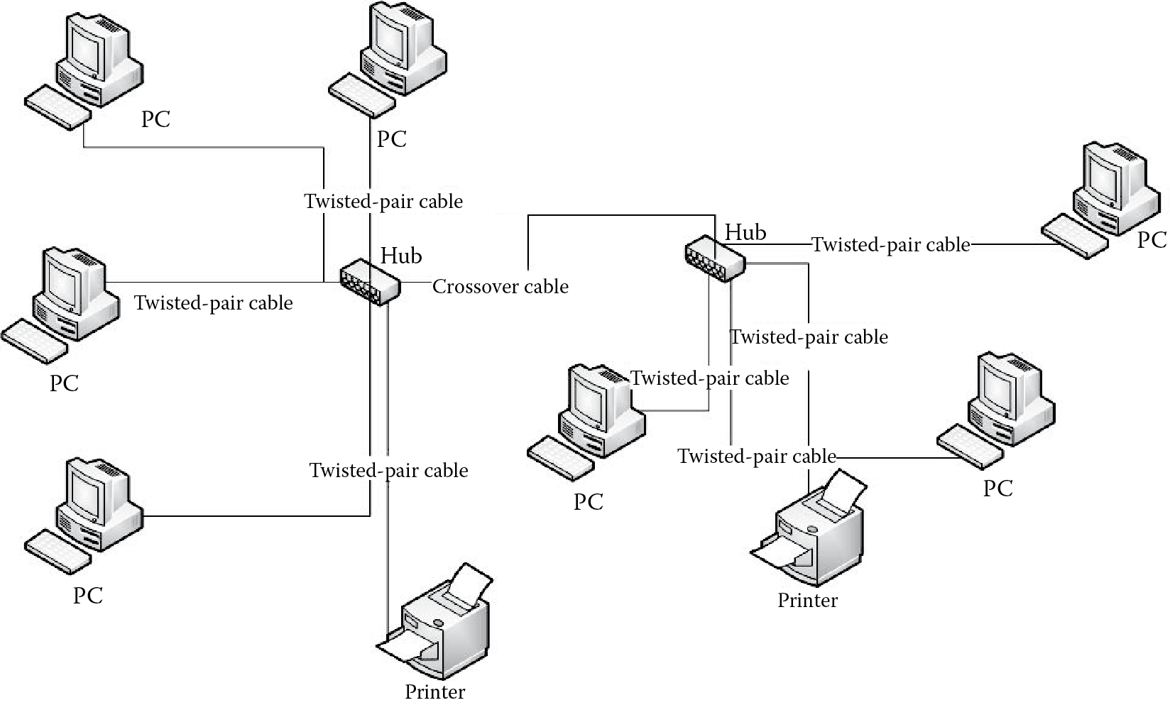
A common approach to building local area networks today is by connecting star networks together. This is done by daisy chaining hubs together. So, for instance, a hub is used to connect the resources of one network together and the hub is connected to another hub, which itself connects the resources of a second network together. This creates a larger single network in which all devices can communicate with each other. In this case, there is an additional transmission required between some of the resources if they are connected to different hubs. As hubs (as well as switches, routers, and gateways) will have a limited number of connections, this approach allows a network to easily grow in size. All that is needed is additional hubs. Figure 12.10 illustrates this concept. The “crossover cable” is used to connect the two hubs together. In this particular figure, the devices on the network are all connected to hubs by twisted wire pair.
In the ring network, devices have point-to-point connections with their neighbors. Communication between devices requires sending a message to a neighbor and having that neighbor forward the message along the ring until it reaches its destination. The ring is easily expanded by adding new devices between any two nodes. However, the larger the ring becomes, the greater the potential distance that a message might have to travel. This, in turn, can create lengthier transmission times. Rings are cheap, like buses, in that there is no dedicated resource that serves as a central point. A ring network could be unidirectional or bidirectional in terms of the direction that messages travel. In a unidirectional ring, if a device were to go offline, it would detach the network into two such that some devices could no longer communicate with others. Assume, for instance, that the ring topology shown in Figure 12.8 were unidirectional and all communication traveled clockwise around the ring. If the topmost device were to fail, the device to the immediate left of the failed device would not be able to reach any other device, whereas the device to the immediate right of the failed device would not be able to receive communication from any other device. A bidirectional ring would require losing two devices before portions of the network became isolated.
The mesh network, also known as a fully connected network, requires that every device have a point-to-point connection with every other device. If there are n devices in the network, there are as many as (n – 1)2 connections. Any device can directly communicate with any other device without concern of message traffic, and if any device were removed, it would not harm the connectivity of the network. However, the mesh network is impractical because of the cost. Not only does it require an excessive number of connections, it requires that every device have n – 1 ports available to make those connections. The mesh network is typically found in high-performance parallel processing computers but not used in computer networks. A small mesh network of six devices is shown in Figure 12.8. With six devices, there are a total of 25 connections. Imagine the number of connections required for a mesh of 50 devices instead. This would require 2401 connections!
The ring network is a form of nearest neighbor network: neighbors are devices that are directly connected together. The mesh network is the ultimate form of nearest neighbor in that every device is connected to every other device so every device is a nearest neighbor. There are many intermediate forms of nearest neighbor networks. These include the tree network: one device is the root node of the tree, and it connects to one or more child nodes, each child then connects to one or more subchildren, and so forth. A common tree is a binary tree in which every node has up to two children. If a binary tree network has n levels, then there will be 2n – 1 nodes, and a message could require as many as 2*(n – 1) transmissions between source and destination nodes. Figure 12.8 shows four forms of nearest neighbor network, a 1-D network, a 2-D network, a 3-D network (not completely drawn), and a tree network. A 4-D network carries the name hypercube.
Aside from the topology, we can classify networks based on their physical size. Size is not a measure of the number of resources so much as the distance between the resources. The most common size of network today is the LAN (Local Area Network). A LAN may be wired (components are connected by a physical medium such as twisted wire pair, coaxial cable, or fiber optic cable) or wireless (components communicate by either infrared light or radio signals of some kind). Most LANs are wired or a combination of wired and wireless. A purely wireless LAN is not common.
Many LANs today are collections of smaller LANs. Consider a university as an example. The university will have computer laboratories. Within any one laboratory, there is one LAN. The resources of the laboratory are connected together via some broadcast device such as a hub or (more likely) switch. If the room is large enough, there may be multiple hubs or switches connected together. In fact, if there are too many devices, there may be a router that connects to multiple switches. This would create several LANs within the one room.
Given that this is a university, the building no doubt contains several computer laboratories. Each laboratory (room) is connected to other laboratories via a router. This gives us a LAN of LANs. These LANs connect to other LANs in the building again via routers, and possibly gateways. For instance, there might be four LANs on the first floor of the building that house Windows machines and two LANs on the second floor that house Macintosh computers. The four first floor LANs are connected together by router, and the two second-floor laboratories are connected together by router. The two routers are connected together by gateway. Other floors of the building have their own LANs to connect together classrooms and faculty offices. Thus, the building contains a LAN of LANs. And this building connects to other buildings in turn. The entire campus constitutes LANs of LANs.
A CAN (Campus Area Network) is, as the name implies, a network that covers some organization’s site, such as a campus. This is obviously a LAN of LANs as described in the previous paragraph. A CAN might extend beyond one regional area as well, perhaps if a campus has branch locations in the city. At the other extreme of local area networks is a PAN (Personal Area Network). The PAN is a small LAN, perhaps connecting together the resources found in a person’s household. Many home computer users now have PANs in which all home computers and a printer are connected together. This may be entirely through wireless connections, or some resources, such as the printer, might be wired. The device connecting these devices may be a network switch or hub, or it might be a MODEM that has the capability of serving as a hub.
A LAN that uses the Internet Protocol (see the section Networks Protocols) is known as an intranet. The advantage of an intranet is that applications intended for Internet usage (e-mail, web browsing, telnet/ssh, etc.) will work internally as easily as they work externally. An extranet is the extension of an intranet over other networks so that access to the intranet can be performed from remote sites. This requires additional security to ensure that remote users are in fact authorized. Typically, a log-in process is used. A virtual private network (VPN) is a common form of extranet. A VPN will often use encryption technology so that messages that physically travel outside of the intranet cannot be understood even if intercepted by techniques such as packet sniffing (this is discussed later in the chapter).
The LAN, CAN, and PAN are small networks in that they connect resources within a small proximity (feet to perhaps a mile in distance). A larger network is the Metropolitan Area Network (MAN), which encompasses a portion of or all of a city. At the small end, a MAN overlaps a CAN in definition. For instance, universities that spread out over several square miles might contain a MAN rather than a CAN (the distinction here is almost irrelevant). At the larger end, the MAN covers an entire city. In such a case, the high-speed physical connectivity of fiber optic cable or radio may be impractical. MANs can be found covering such cities as London (England), Geneva (Switzerland), and San Francisco (California, USA). We can continue to extend the reach of network beyond the MAN to create a WAN (Wide Area Network). These might connect resources across a county, state, country, or the entire world. One such WAN is called Sohonet, which links together various film production and postproduction companies across the world (from LA to New York, Canada to New Zealand, and many European cities). The largest WAN is the Internet.
We briefly consider one form of implementation for a LAN. One of the most popular implementations is called an Ethernet. First developed in the early 1970s, the original commercial release of Ethernet was produced by 3Com in 1980. Ethernet was standardized in 1982 and was a competitor of the Token Bus and Token Ring forms of networks. Although originally implemented using a bus topology over coaxial cable (with T connectors), modern Ethernet networks can use twisted wire pair and fiber optic cable with devices connecting to hubs or switches. By plugging resources directly into a hub or switch, not only is it more efficient but it also reduces installation costs and improves network management.
Ethernet technology has improved over the years, from a theoretical bandwidth of 10 Mbps to a current upper bandwidth of 100 Gbps. Ethernet introduced a number of networking concepts that are commonly found today. These include collision detection mechanisms, Ethernet repeaters, a 48-bit MAC (media access control) addressing scheme for source and destination addresses, the Ethernet frame format, error handling mechanisms, and a variety of adapters so that many different types of computers could connect to an Ethernet. Here, we briefly look at just the collision detection scheme.
The form of collision detection introduced by Ethernet is called Carrier Sense Multiple Access with Collision Detection (CSMA/CD). First, a device prepares a message to transmit. It attempts to sense whether the network media is busy. If so, the devices waits until the media is no longer busy. Then, it places its message onto the media. However, if another device is waiting, both devices could place messages on the media at the same, or nearly the same, moment. Therefore, even though it is transmitting, the device also attempts to sense if any other message is coming across the media. If so, a collision is detected. The device immediately stops transmitting the data and sends out a jam signal. The jam signal is used to alert other resources not to transmit at that moment. The jam signal also, since it is being transmitted over the same media that contains an actual message, overrides the message. Any receiving device will pick up the jam signal and know that the message it was receiving was corrupted. Now both sending devices wait a random amount of time before retrying their transmissions. When switches were added to Ethernet over hubs and bus connections, collisions were reduced, but CSMA/CD continued to be used.
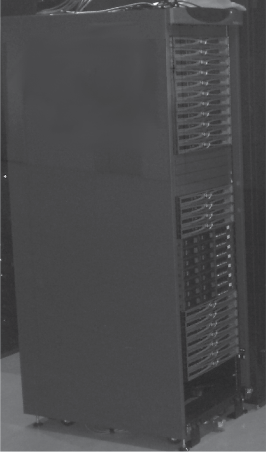
We can also classify networks by the role that computers play within the network. Specifically, we refer to networks as either peer-to-peer or client–server networks. A peer means that each computer is roughly equal to every other computer. This differentiates a network from that of a client–server model. The client is a computer that will request information from another computer. The server is a computer (or device) that takes requests and responds with the requested information. The client–server network then is a network that contains one or more servers. Peer-to-peer networks are cheaper, although the need for servers forces most networks to follow the client–server model. Servers, in many cases, are more expensive computers as they typically require greater hard disk storage and faster response time than the other computers in the network. Servers often look like large system units, perhaps with multiple hard disk drives. Large file servers are often a collection of smaller units mounted into a cabinet, as shown in Figure 12.11.
There are a variety of types of servers based on the type of service desired. One type of server is the file server. In this case, the server’s role is to send files over the network at the request of clients. The typical file server responds to requests over the LAN and services only computers on the LAN. File servers may be used to support both application software and data files. That is, clients will store only their own operating systems. A user wishing to run software may have to load that software over the network on demand. Or, the file server may be limited to only a few, shared applications software and/or data files.
Another form of server is the web server. This is a special type of file server in that it still stores data files (web pages) and programs (scripts). However, the web server responds to client requests from anywhere on the Internet rather than just the LAN, and the requests are specifically http (hypertext transfer protocol) requests. Responses may be html files, documents stored on the file server, or web pages that were dynamically generated through server CGI (common gateway interface) scripts. The web server has several duties that the file server does not, including running server side scripts, logging requests and errors, and handling security.
Yet another form of server is the database server. It responds to client database queries with responses pulled from the database. Additionally, the server may generate reports from data obtained from the database management system. Like the file server, the database server typically responds only to local clients. Both the file server and the database server could respond to authorized clients from remote locations if the server was accessible over a wider area network. But like the web server, the duties of the database server go far beyond file transfer.
Other servers include print servers, mail servers, and ftp servers. Unlike the other servers, the print server does not return a file, but instead monitors print jobs and replies with an acknowledgment that the print job has completed, or an error message. In the case of a mail server, one submits e-mail to the server to be sent to another e-mail server. The two e-mail servers communicate with each other, and once the e-mail is received at its destination, the recipient server informs the recipient user that new e-mail has arrived. An ftp server is much like a web server or file server in that requests are for files and responses are the files.
Network Protocols
A protocol is the set of rules established to govern how people behave and interact with each other. This might be considered a form of diplomacy or etiquette, or the means by which a researcher will report results to other researchers. A computer network exists at several different layers. We might think of how the network works at the hardware layer when discussing the media and the physical form that communication will take. We might discuss how the network will ensure reliability through error handling information. Or we might focus on how application software prepares messages for broadcast. In fact, each one of these steps is necessary and we must specify not only how they work, but how the steps work together. That is, we will consider network communication as a series of layers and a message must be translated from one form to another as it moves from layer to layer.
A network protocol provides the rules by which the layers of a network communicate with each other. This, in turn, provides rules by which different networks can communicate with each other. This also informs network programmers and administrators how to implement, manage, and maintain a network.
The most common protocol at the physical level is the Ethernet protocol, which specifies such aspects of the network as the types of cable that can be used, the collision processing mechanism (CSMA/CD), and the allowable types of topologies: bus, star, tree. Other existing popular protocols are LocalTalk, developed by Apple computers, Token Ring (developed by IBM), and ATM (asynchronous transfer mode), which directly supports audio and video transfer.
Perhaps the most commonly used network protocol is TCP/IP (Transmission Control Protocol/Internet Protocol),* which is a requirement of all computers that communicate over the Internet. So, although computers may use other network protocols, they must also run TCP/IP. As an alternative, the Open Systems Interconnection (OSI) model was a proposed standard for all network communication. So, although TCP/IP is a concrete protocol, OSI is often used as a target for new network developers. Today, both TCP/IP and OSI are commonly cited models for network protocols, so we will examine them both here.
The OSI model consists of seven layers, as shown in Table 12.1. Each layer is numbered, with the topmost layer numbered as 7 and the bottommost layer as 1. The top four layers are known as the host layers because the activities of these levels take place on a host computer. These layers package together the message to transmit, or receive the message and analyze it. The bottom three layers are known as the media layers because it is at these layers that messages are addressed, routed, and physically transmitted. Although OSI is not a specific protocol, it has been used to create network protocols, including Common Management Information Protocol, X.400 electronic mail exchange, X.500 directory services, and the IS–IS (Intermediate System to Intermediate System) routing protocol.
OSI Model Layers
|
Data Unit |
Layer Number and Name |
Function |
|
Data |
7. Application |
User interaction with application software |
|
6. Presentation |
Data representation, encryption/decryption |
|
|
5. Session |
Host-level communication, session management |
|
|
Segments |
4. Transport |
Reliability and flow control |
|
Packet/Datagram |
3. Network |
Logical addressing, routing |
|
Frame |
2. Data link |
Addressing |
|
Bit |
1. Physical |
Physical media, signal transmission in binary |
Layer 1, the lowest layer, is the physical layer. This layer dictates how the device that wishes to communicate (e.g., a computer or a hub) will carry out the communication over the transmission medium (coaxial cable, fiber optical cable, etc.). This layer requires such details as the voltage required for transmission, how to modulate the signal (if needed), how to establish and how to terminate the connection to the communication medium. When establishing a connection, the layer requires the capability of detecting message traffic (contention) and a means of resolution when there is traffic. When transmitting data, this layer receives the data from layer 2 and must convert it into a form suitable for transmission. When receiving data, this layer obtains the data from the transmission medium (electrical current, sound waves, light pulses) and converts the data into a binary format to be shared with layer 2. Thus, this layer deals with the message as a sequence of bits. There are numerous implementations of layer 1 including IEEE 802.3, IEEE 802.11, Bluetooth, USB, and hubs.
What Is 802?
You may have seen notations such as IEEE 802.xx. What does this mean? IEEE is the Institute of Electrical and Electronics Engineers. Among the various efforts of the organization are a number of standards that they have established. Although standards are by no means laws or requirements, most implementers attempt to meet the established standards to guarantee that their efforts will be used and usable.
Most telecommunications standards are put forth by the IEEE and they are labeled as IEEE 802.xx, where the 802 stands for “February 1980” for the first month that IEEE met to discuss telecommunications standards (it was also the first freely available number).
What are some of the standards that go under IEEE 802?
- IEEE 802.3—Ethernet
- IEEE 802.7—Broadband LAN
- IEEE 802.10—LAN security
- IEEE 802.11—Wireless LAN (a number of variations have been produced, each given a letter such as 802.11 b, 802.11 g, and 802.11 n)
- IEEE 802.15.1—Bluetooth certification
- IEEE 802.22—Wireless area network
- IEEE 803.23—Emergency services workgroup
Aside from IEEE 802, the IEEE has established a number of other standards ranging from floating point representations in computers (IEEE 754) to the POSIX standard (portable operating system interface) that Unix and Linux systems meet (IEEE 1003) to standards in the field of software engineering (IEEE 610).
Layer 2 is the data link layer. If a message is intended for a device on the same network (e.g., one that shares the same hub or switch), communication will occur at this level and will not require layer 1. At this level, data are formed into units called frames. The frame must indicate frame synchronization, which is a sequence of bits at the start of the message. This layer contains two sublayers. The upper sublayer is the Logical Link Control (LLC) sublayer. This layer provides multiplexing, which is the ability to carry of several overlapping messages at a time. Through multiplexing, it is possible that multiple messages are of different network protocols, coexisting at the same time, sharing the same network media. The lower sublayer is the MAC. MAC addresses are used to denote a device’s location within a given network. The MAC sublayer allows devices in the same network to communicate together by using only their MAC addresses. This sublayer serves as an interface between the LLC sublayer and the physical layer. Layer 2 implementations include IEEE 802.2, IEEE 802.3, PPP (Point-to-Point Protocol), X-25 packet switch exchange, and ATM. Ethernet is an implementation for both layers 1 and 2.
Layer 3 is the network layer. At this layer, the physical characteristics of the network are not a concern. Instead, this layer views data as variable length sequences with host and destination addresses. This layer handles routing operations. Messages that arrive at a device whose job is to route the message onward will examine the destination address with entries in its own routing table to determine which network to place the message onto. Therefore, routers operate at this level. At this layer, message components are formed into individual packets. The message being transmitted by the sending device will likely consist of multiple packets, perhaps dozens or hundreds depending on the message’s size. Layer 3 implementations include IP (see TCP/IP below), AppleTalk, IPX (Internet Packet Exchange), ICMP (Internet Control Message Protocol), and ARP (Address Resolution Protocol).
Layer 4 is the transport layer. Its primary responsibility is to provide transparency between the upper levels of the protocol and the physical transfer of individual packets. At this level, messages are represented as segments to be divided into smaller units (e.g., packets). Among the services provided at this layer are reliability and control flow. For reliability, this layer must ensure that the packet is received, and received with no error. Details for handling reliability are described below. Control flow occurs when the two devices communicating with each other over the media are communicating at different rates (speeds), such as when two computers have different MODEM speeds.
To handle reliability, layer 4 must ensure that packets lost en route are replaced. There are a variety of mechanisms for handling this. A simple approach is to stamp every packet by its sequence number within the overall message, such as 4 of 7. The receiving device expects seven packets to arrive. If all packets arrive other than number 4, the sending device must resend it. Additionally, every packet will contain error detection information, such as a checksum. The checksum is a computation based on the binary values that makes up the message.
One simple computation for a checksum is to add up the number of 1 bits in the message. For instance, if a binary message consists of 256 bits, and 104 of those are 1s and the remaining 152 are 0s, then the checksum would be 104. However, typically, the checksum should be fixed in size. To accomplish this, a checksum function might add up the number of 1 bits and then divide this by a preselected value. The checksum then becomes the remainder of the division (this is the mod, or modulo, operator). The idea of using mod is known as a hash function. There are a number of different checksum algorithms including fingerprints, randomization functions and cryptographic functions. In any event, upon receipt of a packet, layer 4 determines if any of the data in the packet is erroneous by comparing the checksum value with the data in the packet. If an error is detected, layer 4 sends out a request so that the packet can be resent. Layer 4 implementations include TCP, UDP (both of these are discussed along with TCP/IP below), and SCTP (Stream Control Transmission Protocol).
Layer 5 is the session layer. This layer maintains a connection between two devices. When two devices communicate, they first establish a session. The session remains open until the devices terminate the connection. In between establishing and terminating the session, the session must be maintained. Additionally, a session that is prematurely terminated can be restored at this layer. It is this layer that handles these tasks (establishing, maintaining, restoring, terminating). Layer 5 implementations include NetBIOS, SAP (Session Announcement Protocol), PPTP (Point-to-Point Tunneling Protocol), and SOCKS (SOCKet Secure).
Layer 6 is the presentation layer. This layer is responsible for translating messages from the given application, which is generating the message, into the form of syntax required by the lower layers. Because of this, layer 6 is sometimes referred to as the syntax layer. It is at this layer that the original representation of the message is converted into a uniform representation. For example, in the C programming language, strings are terminated by a special character, �. At this layer, any � characters can be stripped from the message. Another example is for hierarchically structured data, such as data in XML notation. Such data must be converted into a flat format. Encryption (for outgoing messages) and decryption (for incoming messages) takes place at this level. Layer 6 implementations include SSL (Secure Sockets Layer), TLS (Transport Layer Security), and MIME (Multipurpose Internet Media Extensions).
Layer 7, the highest layer, is the application layer. At this level, the end user or application program creates the message to be transmitted, or at this level, the application program presents a received message to the end user. This layer includes various network communication programs such as telnet; ftp; electronic mail protocols such as POP, SMTP, and IMAP; and network support services such as domain name system (DNS).
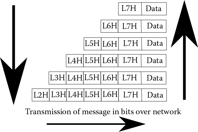
The OSI Model works as follows. A message is created through some application software at layer 7. This initial message is considered the data to be transmitted. Layer 7 affixes a header to the front of the message and maps the message to layer 6. At layer 6, an appropriate header is added to the message. The message, now consisting of the original data and two headers, is mapped into layer 5, and another header is affixed to the front of the message. The top three layers operate on the message as a whole rather than the segmented units operated on starting at layer 4. At layer 4, the message is divided up into packets and then into smaller units until, at layer 1, the message is treated as individual bits. Layers 4 and 3 also affix header information and layer 2 adds both header and footer information. Finally, at layer 1, the message is transmitted. A received message is similarly mapped upward through each layer, removing the header (and footer) as needed until the message arrives at the topmost layer and delivered to the application software. Figure 12.12 illustrates the mapping process in OSI.
TCP/IP is the other, commonly used, transmission protocol. TCP/IP comprises two separate protocols that were united early in the development of the Internet. TCP handles reliability and ordered delivery of packets. It operates at higher levels of the protocol stack, saving the details for how packets are transmitted to the IP portion. Although TCP is used extensively for Internet communication, some applications use User Datagram Protocol (UDP) in its place. Both TCP and UDP sit on top of IP, the Internet Protocol. Here, we briefly examine the layers of TCP/IP and compare them to the layers found in OSI. Unlike OSI, the layers of TCP/IP are not as proscriptive. That is, they describe what takes place at those layers, but they do not offer details on how those actions should take place. Therefore, there are many different ways to implement the TCP/IP stack.
The lowest layer of IP is called the Link Layer. The Link Layer corresponds directly to the lowest two levels of OSI. This layer performs all of the services in the physical and data link layers. The second layer of IP is the Internet Layer. This layer is responsible for sending packets across one or more networks. At this level, addressing and routing take place. It is at this level that IP addresses are utilized. TCP/IP layer 2 is similar to OSI layer 3. However, OSI permits communication between devices on the same network in its layer 2, whereas all routing takes place at layer 2 of TCP/IP. There are other substantial differences between OSI Layer 3 and TCP/IP layer 2, but these are not covered here.
It should be noted that the addressing and routing referred to here are from IP version 4 (IPv4), the current and more popular version of IP. However, because of a limitation on the number of IP addresses, and because of an interest in improving the Internet, IP version 6 has become available. IPv6 will make significant differences in Internet usage as demand increases over the next decade. One of the biggest differences between IPv4 and IPv6 is the form of addresses. In IPv4, machine addresses consist of 32 bits divided up into 4 octets. Each octet is 8 bits (1 byte) and thus can store a number between 0 and 255. The octets of the IP address are separated by periods. For instance, an IP address might be 127.31.49.6.
There are three classes of networks with respect to IP addressing (the practice of assigning classes to networks was discontinued in 1993 although network addresses are often still assigned this way). The class of network dictates which bits of the four octets specify the network on which the computer is housed and the remaining bits denote the machine’s address on its network. Class A networks only use the first 7 bits of the first octet to denote the network address. This limits the number of class A networks to 128, but leaves 25 bits for addresses within the network, and thus class A networks can have as many as 16 M (more than 16 million) internal addresses. Class B networks are denoted with first octet addresses of 128–191 and use the first two octets to identify the network. This leaves 16 bits for network addresses, or 65,536. Class C networks, the most common, use the first three octets for the address allowing for millions of class C networks. However, the class C network then has only a single octet for each device’s address on the network. Therefore, a class C network can only contain up to 256 addressable devices. See Table 12.2 for details. Notice that two classes have reserved first octet address values but have not been used to date.
Internet Network Classes
|
Class |
Octets for Network Address |
Octets for Address in Network |
Number of Addresses for Network |
Legal Addresses (1st Octet) |
Comments |
|
A |
1 |
3 |
16,777,216 |
0–127 |
Many addresses have gone unused |
|
B |
2 |
2 |
65,536 |
128–191 |
|
|
C |
3 |
1 |
256 |
192–223 |
|
|
D |
Not defined |
Not defined |
Not defined |
224–239 |
Multicast addresses only |
|
E |
Not defined |
Not defined |
Not defined |
240–255 |
Reserved (future use) |
IPv4 addresses are 32 bits long. This provides for 232 different (distinct) addresses, or approximately 4 billion unique IP addresses. Although this looks like a large number, the limitation has created a problem in that we have reached this limit because of handheld devices (e.g., cell phones) connecting to the Internet. Furthermore, many of the IP addresses that would normally be available have not been utilized. For instance, class A networks may have enough addresses for more than 16 million internal devices, but this does not mean that every class A network uses all of the available addresses. On the other hand, an organization might be granted a class C network address but may require more than 256 distinct addresses.
In IPv6, addresses are 128 bits in length and often displayed using hexadecimal notation. The advantage of the longer address is that it provides as many as 2128 distinct IP addresses. This gives us plenty of addresses for a very, very long time, even if we provide a different address for every processor on the planet (including those in cell phones, sensors, and other electronic devices). The 128-bit address is usually composed of two parts, a 64-bit network address prefix used for routing across the Internet, and a 64-bit interface identifier to denote the host within the network. An example address might be 1234:5678:90ab:cdef:1234:5678:90ab:cdef. Notice the use of hexadecimal in the address rather than binary or decimal as we typically view IPv4 addresses.
TCP, the upper layers of TCP/IP, also consists of two layers: the Transport Layer and the Application Layer. The Transport Layer is similar to OSI’s Transport Layer (OSI layer 4). However, TCP allows for two different forms of data streams, those using TCP and those using UDP.
UDP does not provide the reliable form of communication that TCP does. When a UDP packet is dropped during transmission, there is no effort to resend it. Although this sounds like a negative, it can be advantageous when real-time communication is more important than data reliability. As an example, real-time audio transmission might use UDP instead of TCP. The rationale behind this is that a recipient would not want the audio signal interrupted while a packet is resent. The omission of one (or even a few packets) would almost certainly not interfere with the recipient’s ability to understand the audio signal.
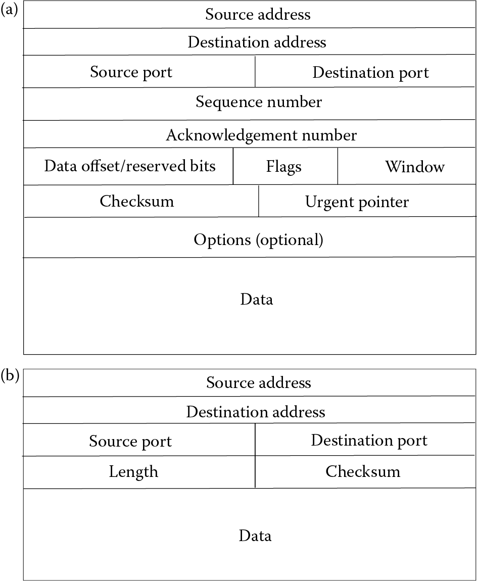
Figure 12.13 illustrates the contents of a TCP packet versus a UDP packet. The UDP packet is far more concise because it lacks such information as a sequence number, acknowledgment information, control flags to specify how the packet should be handled, and a data offset, indicating the size of the data field. The urgent pointer is optional in the TCP packet but can be useful for denoting the last urgent data byte in the data field.
The highest layer of TCP/IP is the Application Layer, which is roughly synonymous with OSI’s top three layers. In the case of the Session Layer of OSI, where a connection is retained until termination, there is nothing precisely equivalent in TCP/IP. However, similar capabilities are handled in TCP/IP’s Transport Layer.
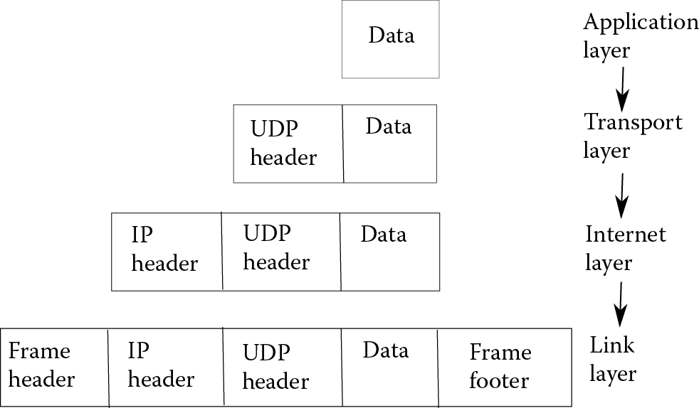
Putting the four Layers of TCP/IP together, we see much of the same functionality as OSI. As with OSI, the message being transmitted or received is converted between layers. Figure 12.14 provides an illustration of how a packet is converted layer by layer in TCP/IP, where each lower layer adds its own header to the previous layer, and the Link Layer adds a footer as well.
Recall that both OSI and TCP/IP are protocols. They dictate several aspects of network communication although they leave other details to implementers. Both require that the protocols be used to translate a message from one format (as generated by some application software) to a format that can be transmitted, and then translated back from the transmitted form to a format that the destination application software can handle. Refer back to Figure 12.12 and Figure 12.14 for the OSI and TCP/IP mappings, respectively. As you might notice, mappings take place from top down and from bottom up. As the message moves down the protocol, more and more details are added such as headers, error checking, and addressing information. As a message moves up the protocol, those added details are stripped off of the message.
One other aspect of note for TCP/IP is that of network handshaking. In fact, whenever two computers communicate over network, before any communication takes place, the two devices must perform a network handshake. In essence, this means that the first machine contacts the second with a message that indicates “I wish to communicate with you” and then it waits. When the second machine is ready, it responds with “I am ready”. Once the handshake is done, the machines can freely communicate until communications are terminated at one end. TCP/IP introduced the notion of a three-way handshake. Here, the first machine sends a synchronization packet (SYN), to the second machine. The second machine, when available, responds back with a synchronization and acknowledgment packet (SYN/ACK). Finally, the first machine responds to the second with an acknowledgment packet of its own (ACK). At this point, the two machines are synchronized and ready to communicate, until communication is terminated. Referring back to Figure 12.13, you can see an “acknowledgement number” in the TCP packet. This is used to support the three-way handshake.
One concept not discussed in our examination of TCP/IP is that of a port. TCP and UDP messages not only require destination addresses but also port addresses. The port is merely an indication of the intended destination software for the message. Thus, when a message is received by a destination machine, the operating system can determine how to handle the message by the port address provided. TCP/IP dictates how that message should be decomposed, but not the application software that should handle it. Ports are dedicated for many different purposes. For instance, the common port used for the SMPT e-mail is 25, and the common ports for http used for web browsing are 80 and 8080. There are port numbers dedicated to ftp (20), telnet (23), ssh (22), and https (443).
Port addresses not only serve the OS, but can also be used by protection software. For instance, a firewall may disallow certain port addresses such as 23 (since telnet is not secure). Similarly a web server may ignore messages that come in from ports other than those expected (e.g., 80, 8080, and 443). Although we limit our discussion of ports here, you will no doubt gain experience with them as you further explore IT.
We finish off this section with one other TCP/IP-related topic: network address translation (NAT). NAT is the conversion of one IP address to another. Basic NAT simply uses one IP address as an alias for another. That is, there is a one-to-one mapping of one address to another. This form of translation might be useful if two networks with incompatible network addresses are attempting to communicate with each other. In basic NAT, the translation process must modify the message’s IP address, IP header, and any checksum of the message that was computed by both the message content and the header information.
However, it is far more common to use NAT to hide an entire series of IP addresses. For instance, an organization might not have enough IP addresses for all of its internal devices. In this case, only some of the machines in the LAN are given actual IP addresses that can be “seen” from outside. The other devices are hidden from view externally. When a message arrives, the destination address must be converted into an internal, private IP address. This form of NAT is called many-to-one, or NAT overload or IP masquerading. A server must be able to determine which private IP address should be used in place of the external address. The translation to the private IP address requires additional modifications because the packet must be routed properly to the correct internal router. Among the modifications, it is possible or even likely that port addresses will be modified as well as IP addresses. The advantages of many-to-one NAT are that they offer a degree of protection because of the privacy of the internal addresses, and permit LANs to have additional IP addresses. The main disadvantage of many-to-one NAT is the complexity it introduces at the server that handles the Internet connection.
Network Software
In this section, we look at common forms of network software. These are programs that we might use to communicate between devices over a network. These are all used in TCP/IP intranets, so these are not necessarily limited to just Internet usage but can also provide service within an LAN.
Telnet is a program that allows an individual to log into another computer over the network. The person performing the telnet operation needs to have an account on the remote (host) computer. A variation of telnet is called rlogin, available in Linux. With rlogin, the user does not have to actually log in to the destination computer because the user’s account information (name, password) will be the same on all networks computers. Linux actually has several “r-utilities”, where “r” stands for “remote.” Aside from rlogin, there is also rfile, rsh, rstatus, and rwho to name a few. The rfile program allows you to perform a variety of file management operations remotely. The rsh program opens a shell to another machine remotely. The rstatus program provides basic receiver status information. The rwho program performs the Linux who command on the remote machine, showing you who is logged in. The idea behind the r-utilities is that they run on a LAN of computers that share the same log in server. The r-utilities do not require that you log in to the remote computer as long as you have logged into your local computer. However, the r-utilities must be set up explicitly for use by a system administrator.
Telnet and rlogin share a problem; neither program is secure. Messages passed between local and remote computers are in clear text. This includes, in telnet’s case, any passwords sent from the local to remote computer. It is therefore possible that messages can be intercepted by a third party who might then view your password or other sensitive material. The ssh utility is a Linux program that performs encryption and decryption automatically on any message sent, thus providing a secure form of communication, unlike telnet and rlogin. Although ssh is part of Linux, it is also available via the putty program for Windows.
Morris’ Internet Worm
On November 2, 1988, a graduate student at Cornell University, Robert Morris, unleashed a program on the Internet intended to demonstrate security holes in Unix. Now known as Morris’ Internet Worm, the program infiltrated about 6000 Unix machines over the course of 3 days, bringing a sizable portion of the Internet to a crawl, or down entirely (it was estimated that there were about 60,000 total computers on the Internet, so the worm impacted 10% of the Internet). The worm specifically attempted to gain entrance to Unix systems through four approaches:
- Guessing weak passwords (including no password at all)
- Exploiting known flaws in the Unix sendmail program such as a buffer overflow
- Exploiting known flaws in the Unix finger command
- Using r-utilities to propagate to other network machines
Once the worm reached a machine, it would upload its full version of itself and make copies to send to other network machines, machines listed in the current machine’s /etc/host table, and other machines through the same four approaches as listed above.
In essence, the worm acted as a denial of service program in that it made so many copies of itself that the infected computers could do little else than run copies of the worm.
For his efforts, Morris paid $10,000 in fines and served 400 hours of community service. The cost of the damage of the worm was estimated at between $100,000 and $10 million. The worm prompted DARPA (Defense Advanced Research Projects Agency) to establish a group that would deal with Internet emergencies and threats in the future.
Ping is a program that will generate and send packets repeatedly to the destination device, outputting acknowledgment messages. This lets you know (1) if your machine can reach the network and (2) if the remote machine is accessible. You can also use ping to see how long the message and response take to determine if you have some abnormal network latency.
A similar program to ping is traceroute. This program outputs the route taken between your computer and the destination computer. You may use traceroute to see how a message (packet) makes it across the Internet, how much time it takes, and if there are routers along the way that are causing problems.
Both ping and traceroute are often considered insecure programs. Clever hackers might use either or both to investigate the computers on a LAN. In this way, the hackers can obtain IP addresses that might not otherwise be public knowledge, and use these IP addresses to stage an attack. Therefore, it is possible that the system or network administrator might disable both of these programs.
HTTP is the basis for web browser communication. An http request sent to a web server results in a page being returned and displayed in the browser. However, there may be times when you want to download the file quickly without displaying it in a browser. You can accomplish this from the command line in Linux using the program wget. In wget, you specify the complete URL (server name, directory path on the server, file name). The file is then downloaded to the current directory.
You can also download files directly using an FTP program. However, in FTP, a session is created between you and the server, which remains open until either you terminate the session, or the session times out. Although most FTP programs are graphical, there is also a command-line version. Graphical versions of ftp include Filezilla, Win-Ftp, and Win-SCP (which includes a secure form of FTP, similar to how ssh is a secure form of telnet). In using ftp to access files on a remote computer, you must either have an account on the remote computer or you must log in as an anonymous user. Anonymous users often only have access to public files on the ftp server.
One large difference between http and ftp is the URL. You commonly submit an http request by clicking on a link in an html document in a web browser. The link encodes the location of the document that you want to retrieve so that you do not have to memorize such information. In ftp, however, you must know the server’s address, and then you must either know the directory path and the file name, or you have to search around on the server to locate what you are interested in. In both http and ftp, the server’s address should be the machine’s IP address. However, since IP addresses are hard to memorize, we have invented a shortcut whereby you can use the machine’s IP alias instead. The alias is an English-like description (or abbreviation) of the destination machine. For instance, we have such aliases as www.google.com for businesses, www.nku.edu for universities and www.usa.gov for government sites.
Routers can only handle IP addresses, not IP aliases, so we have to provide a form of translation from alias to address. This is handled by DNSs. A DNS server is merely a computer running a DNS program and data files that provide mapping information. Additionally, the DNS has pointers to one or more DNSs on the Internet so that, if the local DNS does not have the mapping information, it can pass the request on to another DNS. DNSs are arranged hierarchically across the Internet so that a request might be passed along from one DNS to another to another to another before the mapping can finally be obtained.
The nslookup program provides a translation from IP alias to IP address for you. This is convenient if you want to make sure that a particular alias has been established in a DNS table. It is also useful if you want to know the physical IP address of a computer, knowing only its alias. If you want to learn your own computer’s IP address, use ifconfig (in Linux) or ipconfig (in Windows).
Three other Linux network commands are arp, used to determine Ethernet connectivity and network card response; netstat, used to determine the status of network connectivity and socket status; and route, which lists the routing tables (including such things as network gateway IP address and local network IP address and masks). Also of note in Linux is the network service command. You can start or stop the network service or check its status. The command looks like this:
/sbin/service network command
where command is down, start, restart, status. The network service is a daemon that must be running for you to be able to use the network (send out messages or receive messages).
Linux has many network-related files worth exploring. A few are listed below.
- /etc/hosts: IP alias to address mapping for machines that your machine will often communicate with. By placing the IP addresses in this file, your machine does not have to communicate with the DNS first, saving time.
- /etc/resolv.conf: stores the address of your DNS. There may be several entries.
- /etc/sysconfig/network-scripts/: stores configuration files that are run during the Linux system initialization process to set up network connections.
- /etc/xinetd.d/: contains services that rely on the network daemon, xinetd.
- /etc/hosts.allow and/etc/hosts.deny: to permit or restrict access to your computer.
- /etc/hosts.equiv: contains IP addresses of “trusted” machines so that r-utilities will work for all computers defined as equiv (equivalent).
Placing your computer on a network invites hackers to attack your computer. This is perhaps one of the most vulnerable aspects to modern-day computing. The ultimate security is to not connect your computer to a network. Naturally, this drastically limits your computer’s capabilities and your own. Therefore, network security software is available. Such software is not just useful these days but essential for anyone who wishes to access the Internet safely. Two of the most common network security software are firewalls and antiviral software.
A firewall can either be software or hardware (in the latter case, it is a dedicated server that runs firewall software). The firewall software contains a list of rules that describe the types of messages that should either be permitted to make it through the firewall and to your computer, and those that should be blocked. Rules can be based on the port number of the message, the type of message, the IP address of the originator of the message, whether the message is in TCP or UDP (or other) format, and protocol (e.g., http, https, ftp). We briefly examined the Linux firewall in Chapter 11.
Antiviral software attempts to identify if a file contains a virus, or more generally, some form of malware. Antiviral software can be run on demand, or you can set it up so that all incoming messages are scanned. Unfortunately, antiviral software will not necessarily catch every piece of malware. As programmers become more ingenious in how to attack an unsuspecting user, antiviral software must become more sophisticated. But the antiviral software always lags behind the innovations of the attackers. Furthermore, you must be diligent in updating your antiviral software often (new releases may come out daily or weekly).
Networks may have their own forms of security, such as intrusion detection and intrusion prevention software. There is no generic solution to preventing intrusions at this point as all operating systems have security holes to be exploited. In fact, hackers often attempt to probe a system’s defenses before they mount an attack. Some of the openings that hackers may find include leaving gaps in the firewall (e.g., ports that are not inspected), leaving wireless connections unprotected, foregoing encryption, not requiring strong passwords, a lack of physical security around network access points, and permitting operations such as ping and traceroute.
Among the more common forms of attacks found today are denial of service attacks on web servers, IP spoofing to intercept messages, ARP poisoning to change IP addresses in a router to be of the attacker’s machine rather than a local machine, buffer overflow that allows a hacker to invade computer memory with their own code, and SQL injections that permit a hacker to invade a database with their own SQL commands. Although these are all known forms of attacks, it does not necessarily mean that a system is protected against them. And as these attacks are known, newer attacks are being thought of. Any organization that values data integrity and the functionality of its computer systems will need operating system level and network security. It is common for mid-sized and large organizations to hire network security administrators in addition to system administrators. We examine data integrity and security in Chapter 15.
The Internet
IP addresses are often difficult to remember, so we allow users to reference servers by aliases, such as www.google.com. In order to translate from an alias to the actual IP address, you need access to a DNS server. Every network either has a DNS or knows where to find a DNS. Most of this is hidden from you as a user, but if you are a network administrator, you will have to either set up a DNS or know where to find one. There are further aliases to restrict what a user might have to remember. For instance, it is common to further alias a web server so that the user does not require the www portion, and therefore although www.google.com is the alias of the Google search engine web servers, so is google.com. The DNS is a computer that has a table that contains IP addresses and aliases. When provided with an Internet alias, the DNS looks the entry up in its own DNS table and returns the corresponding IP address. The IP address is then sent back to your computer.
Computer networks have existed for decades. In the past, most computer networks were local area networks (LAN), and they were isolated—you could communicate within the network, but not outside of the network. The Internet changed all of this. To communicate over the Internet, a machine needs to run the TCP/IP protocol. With the popularity of the Internet, all computers today run TCP/IP. A computer connected to a LAN can also communicate over the Internet if the LAN has a connection to the Internet, and most do. We have blurred the lines of where one network stops and the next starts. A network connecting computers in a single room is connected by router to a network connecting computers in another room. The network that exists on one floor is connected to the network on another floor. The networks of one building are connected to the networks in other buildings. A LAN might be considered any one of these networks, or the network that covers the entire campus. With VPNs, the network can expand to include those logged in remotely from other sites. The network for the organization is most likely connected to the Internet as well. With Internet Service Providers (ISPs), computers in people’s homes also connect to the Internet making the Internet a network of networks. So you might think of the Internet as an extension to the LAN of your current computer. There are three technologies “gluing” these computers together:
- Packet switching. The telephone network uses circuit switching—when you dial a number, a pathway is set up between the source phone and the destination phone and that pathway remains fixed and established until one of the phones hangs up. Cell phone networks, carrying voice (but not data), are similar although the circuit can change as you move because you are routed to the nearest available cell phone tower. Packet switching, on the other hand, breaks the communication down into small packets of data and each is sent across the network separately. Each packet could potentially take a different pathway to reach the destination. Packet switching was pioneered in the 1960s when the Internet was first being constructed.
- Routers. The router is the device that permits packet switching so that a message can be routed to the next link in the network “on the fly.” The router is a device that receives a message, examines its destination IP address, and sends the message on to the next location in the network, another router. At the destination network, routers route messages until they reach a LAN, and finally the LANs router or switch sends the message to that one destination machine.
- IP addresses. Part of the TCP/IP protocol is addressing rules. An IP address consists of four numbers, where each number is between 0 and 255. For instance, 10.11.241.105 is an IP address. Each number is actually stored in 1 byte of memory (1 byte is 8 bits, and 8 bits can store any number from 0 to 255). This makes an IP address 4 bytes or 32 bits in size. Since IP addresses are difficult to remember, we often reference machines by an IP alias, an English-like name (for instance, www.google.com). In order to translate from an IP alias to an IP address, we use a DNS. As mentioned earlier, because of the limitation now being felt by the 32-bit addresses, IPv6 uses 128 bits for IP addresses.
The three classes of IP addresses currently in use dictate how to interpret the 4 octets of the address. In class A IP addresses, the first octet is the network ID and the remainder of the octets constitute the computer number. Class B addresses split the address into network ID for the first two octets and the machine number in the last two octets. Class C addresses use the first three octets for the network address leaving one octet (256) for the machine number. The class identification of the network part of the address can be subdivided even further through a process called subnetting.
You may have seen the term subnet mask. What is a mask (or netmask)? We often compute values in a computer using the AND or the OR operation on binary bits. For instance, the two bytes 10101010 and 00001111 when ANDed together yield 00001010 and when ORed together yield 10101111. These operations work bit-wise, that is, we perform the AND or OR operation on the first bit of both numbers to yield a new first bit (1 AND 0 is 0, 1 OR 0 is 1). We do this for all eight pairs of bits. The AND operation returns a 1 if both bits are a 1 (0 otherwise) and the OR operation returns a 1 if either bit are a 1 (0 otherwise).
Now, why do we use these? Imagine that you have the following IP address in binary:
00001010.00001011.11110001.01101001 (10.11.241.105)
If we AND this with 11111111.11111111.11111111.00000000, what do we get? We get
00001010.00001011.11110001.00000000
What does this value represent? We started with 10.11.241.105 and the result of the AND operation gives us 10.11.241.0. For a class C network, what we have obtained is the IP address of the network that houses our computer. On the other hand, if we AND the number with 00000000.00000000.00000000.11111111, we get
00000000.00000000.00000000.01101001
This value, 0.0.0.105, is our computer’s specific address on the network.
The bit patterns 00000000 and 11111111 are the integer numbers 0 and 255, respectively. We use the values 255.255.255.0 and 255.0.0.0 as netmasks. Two combinations that we would not use are 0.0.0.0 and 255.255.255.255 because such netmasks would either return 0.0.0.0 or the entire original IP address, so neither would provide us with useful information. The subnet mask is used to easily obtain the network number and the subnet number is used to obtain the device’s address on the network. You may also see an IP address referenced like this: 10.11.241.0/24 or 10.0.0.0/8. This is simply another technique for defining the subnet mask. The number after the / refers to the number of binary 1’s in the mask. Therefore, a mask of 255.255.0.0 can also be referred to as /16.
How the Internet Works
Briefly, the Internet works as follows. You want to send a message from your computer to another computer (e.g., e-mail message, http request for a web page, ftp request, ssh, or telnet communication). Your computer takes your message and packages it up into one or more packets. Packets are relatively small. If the message is short, it can fit in one packet. As an example, the request http://www.google.com/ will be short, but an e-mail message could be thousands to millions of bytes long so it might be placed into multiple packets. Each packet is given the destination address (an IP alias), a checksum (error detection information base, which often is computed by summing up the byte values of several bytes and then doing some compression type operations on that sum and then summing the sums), and a return address (your machine’s IP address so that the destination computer can send a response).
As the packet is assembled, the destination IP alias is translated into an IP address. Your computer stores the address of your site’s DNS (in Linux, this is stored in /etc/resolv.conf). Your computer sends a message to the site’s DNS to translate the IP alias to an IP address. If the local DNS does not recognize the IP alias, then a request is passed on to another DNS. The DNSs on the Internet are organized as a hierarchy. Ultimately, a DNS will recognize the alias and respond to those below it with the address. Each receiving DNS will update its own tables (if necessary). However, if the DNS at the highest level of the hierarchy does not recognize the alias, an error is returned and your message will never make it out of your computer.
Once the IP address has been provided, the packets are sent out. They are sent from your computer to your site’s Internet point of presence (or gateway). The message is routed from the current LAN to this gateway. From there, the server sends each packet along one of its pathways that connect it to the Internet. Each packet finds its own way across the Internet by going from one router to another. Each router selects the next path based on the destination address and the current message traffic along the various paths available. The packet might traverse a single link, two links, or dozens of links. Use the traceroute command to explore how many hops a message might require.
Upon receiving a message at the destination site, the destination IP address may or may not be the actual IP address of the destination host. If NAT is being used at the remote site, the IP address is translated from an “external public” address to an “internal private” address. And now with the internal private address, the message continues to be routed internally to the destination network and finally, by switch to the destination computer. Usually there are fewer pathway choices internally and in fact a message may have only one route to take. Once received by the destination computer, that machine’s operating system saves the packet. The packet is mapped up the protocol stack, and all packets of the same message are combined together as they arrive. They are sequenced based on sequencing numbers (such as packet 3 of 5). Once all packets have been received, the final message is presented to the appropriate application software (or stored to disk in such a case as an ftp or wget communication). Note that the ordering of packets is not done by IP, but rather by the higher-level TCP protocol. The destination machine packages together a response to the sending device to alert it that the message was received in full and correctly (or if any packets were dropped or arrived with errors). The entire process takes seconds or less (usually) even though the distance traveled may be thousands of miles and the number of hops may be in the dozens.
The Internet versus the World Wide Web
Although most people use the terms interchangeably, they are not the same. The Internet, as discussed in this chapter, is a computer network. It is a worldwide network but it is still a network—the computers and computer resources that we use to communicate with each other, the media connecting these devices together (whether cable, radio, microwave, or satellite-based), and the broadcast devices such as switches and routers. The Internet is a physical entity; it contains parts you can touch and point to.
The World Wide Web is a collection of documents, linked together by hyperlinks. These documents are stored on computers that we call servers. And these servers are among the various computers connected to the Internet.
The World Wide Web then sits on top of the Internet. We could continue to have an Internet without the web, but without the Internet, there would be no web.
Another point of distinction worth noting is of people who comment that they have lost their Internet, or that the Internet is down. What has happened is that they have lost their ability to connect to or communicate over the Internet. But the Internet should never be down. It was built to survive a nuclear war and it would take a lot of destruction for the Internet to be lost.
Brief History of the Internet
In 1968, four research organizations were funded by the Department of Defense (DOD) to create a computer network for long-distance communication. These organizations were the University of Utah, the University of California at Los Angeles (UCLA), the University of California at Santa Barbara, and Stanford Research Institute (SRI). Their intention was to build an “electronic think-tank” by having a computer network that could accommodate the transfer of files and allow remote access to each other’s computers. They enhanced the fairly recently proposed packet switching technology ideas into practice and used telephone networks to connect these computers together. This network was dubbed the ARPANET. The first message was sent between UCLA and SRI on October 29, 1969.
The original protocol used was called 1822 protocol. This protocol was not very efficient and would eventually be replaced by TCP/IP in 1983. The first e-mail message was sent over the ARPANET in 1971. FTP was added in 1973.
As time went on, more computers were added to the network. By June 1970, there were nine computers on the network. By December 1970, there were 13 computers, and by September 1971, there were 18. Between 1972 and 1973, 29 and then 40 computers were placed on the ARPANET.
Two satellites made available to support ARPANET communication and computers in both Hawaii and Norway were added in 1973, making the network international. By 1975, the network had reached 57 computers. Also in 1975, the DOD handed control of the ARPANET from ARPA to the Defense Communications Agency (another part of the DOD). In 1983, the military portion of the network (MILNET) was separated. Before this split, there were 113 computers and afterward, 68.
In 1974, the UK developed its own form of packet switched network, X.25. X.25 became publicly available. Other networks were created in the late 1970s and early 1980s. These, along with ARPANET, would eventually become components of the Internet.
In 1979, two Duke students created UUCP for sharing messages via an electronic bulletin board. This became known as Usenet news. Usenet was made available over a number of networks and people could access the network using dial-up over a MODEM from their home computer or from a networked machine.
In 1983, with the creation of TCP/IP, the ARPANET was renamed the Internet. The various previous networks that were connected together became the NSF Backbone, which would become the Internet’s backbone as the Internet continued to grow. In the 1980s and early 1990s, NSF sponsored an initiative to provide Internet access to as many U.S. universities as possible. In the meantime, pay networks (AOL, Genie, Compuserve, etc.) began connecting to the Internet.
From the late 1980s through the mid 1990s, there were several other developments that would change the Internet. First, access was being made available to the public through pay networks, libraries, schools, and universities. Second, hypertext documents were being pioneered. Third, the U.S. government passed legislation to make it easier for companies to offer Internet services and therefore provide more access to home computer users. However, many people were still uncomfortable trying to access the Internet.
Around 1994, the idea of a web browser was developed. The first one was known as Mosaic. The idea behind the web browser was that the browser would load and display a document automatically. The document would include hypertext information (links). Clicking on a hypertext link would activate a command for the browser to send out an http request for a new document to be sent from a server. The document would be sent back and displayed in the browser. Until this time, most users had to understand how to send messages (whether ftp, telnet, e-mail, or other) including knowing how to specify IP aliases or addresses. But with web browsers, the user only had to know how to click on links. Over time, the web browser has replaced most other methods of Internet communication except for e-mail for the typical user.
Where are we today? Hundreds of millions of computers make up the Internet. The exact number is difficult to tell because home computer users do not leave the computers on all the time. When we factor in handheld devices, the number exceeds 4 billion. The number of actual Internet users is also an estimate, but between home computers and handheld devices, it is estimated that (as of 2012) there are more than 2 billion users (approximately one-third of the population of the planet). Figure 12.15 indicates the growth that we have seen in Internet users since 1995.
And the web? There are perhaps trillions of documents available over the Internet. Many of these documents are hypertext (html) documents with hyperlinks to other documents. However, a large number of documents are data files (word documents, pdf documents, powerpoint documents, etc.).
Today, control of the Internet is largely in the hands of corporations that provide Internet access. These include many telecommunications companies thanks to the US 1996 Telecommunications Act. This act, among other things, allowed telephone companies, cable companies, cell phone companies, and others to serve as ISPs. Up until this point, Internet access was largely made available either through employers and universities or through pay WANs such as CompuServe, America On-line, and Prodigy.
So telecommunications companies control access to the Internet. But who controls the Internet itself? In some regard, all of the users control the Internet in that we are all responsible for the content being placed onto the Internet—through our web pages, through e-mails that we send and files that we upload and download, and through our participation on message boards, blog sites, and so forth. Some aspects of the Internet, however, have been handed over to a variety of international consortia.
One such organization is known as the Internet Corporation for Assigned Names and Numbers (ICANN). This organization provides IP addresses and handles domain name (IP alias) disputes. A department of ICANN is the Internet Assigned Numbers Authority, who as their name implies, hand out IP addresses. These addresses are based on geographical location, so, for instance, one set of IP addresses is issued to sites in North American and another in Europe and western Asia.
Another organization is the World Wide Web Consortium (W3C). This organization provides standards for web site construction including the next generation of the html markup language, the use of cascaded style sheets, the use of XML, and concepts related to the semantic web.
Future of the Internet
Obviously, the Internet has had a tremendous impact on our society. The advantages that our society has gained because of the Internet are perhaps too numerous to list. However, there are also significant problems with the current state of the Internet today. Solutions to these problems are currently being researched.
- Dial-up access. Many people have used the telephone network to obtain access to the Internet through an ISP. The problem is that the telephone network consists primarily of twisted wire pair, and this medium can only support a limited bandwidth of message traffic (approximately 56,000 bps). Downloading a 1 MB file (a small picture for instance) would take 18 seconds at this bandwidth. Although other technologies are now available such as digital cable and direct digital subscriber lines (DSL) to people’s households, there are still millions of households forced to use the slower technology. This has been called last mile technology because most of the telephone network uses fiber optic cable except for the last stretch between the subdivision and the home itself. To replace this last mile or two of twisted wire is cost prohibitive. The telephone companies are only slowly replacing it. Although it seems unlikely that last mile technology impacts people in larger cities, many people who live on the outskirts of a city or in rural areas largely must rely on the telephone lines for access to the Internet. One solution to this problem is through a satellite antenna. Downloading information is done very rapidly as the satellite has a much larger bandwidth than the telephone lines. However, uploading must still be done through the telephone lines, so this only offers a partial solution. Another solution to this problem is the use of cell phones. However, cell phone networks often are overcrowded and so their bandwidth will ultimately be limited as well. In fact, 3G networks are set up to drop packets when there are too many messages going across the network. The 4G networks are promising to resolve this, but 4G coverage is spotty.
- TCP/IP seemingly offers 4 billion unique IP addresses (32 bits gives you 232 or roughly 4 billion combinations of addresses). However, not all of the addresses are being used. Consider for instance a small organization that is given a Class C net work address. They are given 256 distinct addresses but do not necessarily use them all. Another organization might require two Class C networks because they have more than 256 addressable devices but fewer than 512. Through NAT, organizations can provide a greater number of IP addresses for their devices, but this solution cannot extend to, for instance, all of the handheld devices that are now using the Internet. Considering that there are 7 billion people on the planet, we have run out of addresses for everyone.
- The Internet backbone was not set up to support billions of users especially when the users are requesting large documents such as images, movies, and music. The result is that the Internet is sluggish.
To resolve some of the problems, IPv6 (IP version 6) is being used by some networks. However, IPv6 cannot solve all the problems and so researchers are investigating technologies for Internet2, a new form of Internet. Whether this will utilize the current backbone or require brand new hardware will be decided in the upcoming years.
Along with the upgrades to the Internet infrastructure and protocols, two additional concepts are present when discussing “Web 2.0”. These are cloud computing and the semantic web. We wrap up this chapter with brief discussions of both of these ideas.
Cloud computing combines several different technologies: distributed computing, computer networks, storage area networks. The idea is to offer, as a service, the ability to offload computation and storage from your local computer to the cloud. Through the cloud, users can access resources that they may not normally have access to, such as increased processing power to support search engines, software that they do not have licenses for on their local machine, and storage in excess of their local file server or computer. Conceptually, a cloud is a step toward ubiquitous computing—the ability to have computation anywhere at any time. In effect, a cloud is the ultimate in a client–server network. The clients are the users who access the cloud remotely and the server is the cloud itself, although unlike a traditional client–server model, the cloud represents service on a very large scale.
To access a cloud, commonly the interface is made through a web portal. In this way, the client computers do not need any specific software downloaded onto their computers. In some cases, clients download specific applications for access. They are also provided a secure account (i.e., an account that requires a log in to gain access). Services offered by cloud computing range from simple storage to database and web services, e-mail, games, and load balancing for large-scale computational processing.
To support a cloud, a company needs a sophisticated network infrastructure. This infrastructure must handle very high bandwidth to support the hundreds, thousands, or millions of users. Data storage capacity might need to run on the order of Petabytes (the next magnitude of storage up from the Terabyte). If the cloud is to support computing as well as storage, dozens to hundreds of high-end processors may also be required. Companies that are making cloud services available (e.g., Amazon, Google, Oracle) are investing billions of dollars in the infrastructure. The result, for a small fee, is that businesses and individuals can have secure data storage (secure both in terms of secure access and the security of mind in that their data are backed up regularly) and remote access to powerful processing. Cloud computing may reach a point eventually where individually, we do not need our own desktop units but instead just interfaces (e.g., handheld devices or wearables), and all storage and computing take place elsewhere.
It should be noted that cloud computing does not have to done by the Internet, but for commercial and practical purposes, most cloud computing exists as a part of the Internet. If a company were to build their own private cloud, its use would be restricted to those who could access the company’s network. In fact, we commonly see this with virtual private networks and extranets. The idea is that a company provides processing and storage, but through the VPN, users of the company’s computing resources can remotely access them. Thus, they carry their computing with them no matter where they go.
Finally, we consider the semantic web. The World Wide Web is a collection of data files, hyperlinked together, and stored on servers on the Internet. The WWW contains a mass of information perhaps reaching the sum total of all human knowledge now that libraries are accessible via the web. However, the information is largely poorly indexed and organized. It is up to an intelligence (human) to sift through the information and make sense of it. The semantic web is a pursuit led by researchers in artificial intelligence to organize the knowledge and provide automated reasoners to not only search through the information but to find useful pieces to present to the human users.
As a simple example, imagine that you want to take a vacation to Hawaii. Through various websites and search engines, you can book a flight, book a hotel, rent a car, and discover events and locations to explore in Hawaii. How much of this process could be automated? Let us assume that you have a representative-bot (a piece of software to represent you). You have described to your bot your interests, likes, and dislikes. You provide your representative-bot a calendar of important dates that limit your travel dates. You might also specify other criteria such as price restrictions. The representative-bot will use this information and communicate with the various websites to book the entire vacation for you, right down to obtaining maps to the locations you should see during your visit. Further, the bot would reason over the events to coordinate them so that proximity, travel time between locations, times of day/evening, and other factors are taken into account.
The semantic web consists of several different components. Website data are now being organized into ontologies: knowledge bases that not only contain information but how that information can be interpreted and used. Small programs, intelligent agents, are being built to handle different tasks such as scheduling, communication, and commerce decision making. New types of query languages are being created to facilitate communication between agents and between agents and ontologies. Combined, it is hoped that these new technologies will move the World Wide Web closer to the vision of a semantic web, an Internet whose resources are easily accessible and whose knowledge can be used without excessive human interaction. The semantic web, whose ideas date back to 2001, is only now being used in such areas as intelligence gathering and medical research. It will probably be another decade or more before we see practical, every day uses.
Further Reading
There are many texts that cover topics introduced in this chapter from computer science texts on network programming and network protocols to engineering books on the transmission media and protocols of networks to IT texts that detail how to set up a computer network and troubleshoot it. Additionally, there are numerous books that describe the development and use of the Internet. Here, we cite some of the more significant texts from an implementation perspective (the first list) and from an administration and troubleshooting perspective (the next list).
- Blum, R. C# Network Programming. New Jersey: Sybex, 2002.
- Forouzan, B. Data Communications and Networking. New York: McGraw Hill, 2006.
- Harold, E. Java Network Programming. Massachusetts: O’Reilly, 2004.
- Kurose, J. and Ross, K. Computer Networking: A Top–Down Approach. Reading, MA: Addison Wesley, 2009.
- Lin, Y., Hwang, R. and Baker, F. Computer Networks: An Open Source Approach. New York: McGraw Hill, 2011.
- Peterson, L and Davie, B. Computer Networks: A Systems Approach. San Francisco, CA: Morgan Kaufmann, 2011.
- Reese, G. Cloud Application Architectures. Massachusetts: O’Reilly, 2009.
- Rhoton, J. Cloud Computing Explained: Implementation Handbook for Enterprises. USA: Recursive Press, 2009.
- Segaran, T., Evans, C., and Taylor, J. Programming the Semantic Web. Cambridge, MA: O’Reilly, 2009.
- Sosinsky, B. Cloud Computing Bible. New Jersey: Wiley and Sons, 2011.
- Stallings, W. Data and Computer Communications. Upper Saddle River, NJ: Prentice Hall 2010.
- Stevens, W. UNIX Network Programming: The Sockets Networking API. Englewood Cliffs, NJ: Prentice Hall, 1998.
- Tanenbaum, A. Computer Networks. Upper Saddle River, NJ: Prentice Hall, 2010.
- Yu, L. A Developer’s Guide to the Semantic Web. New Jersey: Springer, 2011.
- Allen, N. Network Maintenance and Troubleshooting Guide: Field Tested Solutions for Everyday Problems. Reading, MA: Addison Wesley, 2009.
- Corner, D. Computer Networks and Internets. Upper Saddle River, NJ: Prentice Hall, 2008.
- Dean, T. Network+ Guide to Networks. Boston, MA: Thomson Course Technology, 2009.
- Donahue, G. Network Warrior. Massachusetts: O’Reilly, 2011.
- Gast, M. 802.11 Wireless Networks: The Definitive Guide. Massachusetts: O’Reilly, 2005.
- Hunt, C. TCP/IP Network Administration. Massachusetts: O’Reilly, 2002.
- Limoncelli, T., Hogan, C., and Chalup, S. The Practice of System and Network Administration. Reading, MA: Addison Wesley, 2007.
- Mansfield, K. and Antonakos, J. Computer Networking for LANs to WANs: Hardware, Software and Security. Boston, MA: Thomson Course Technology, 2009.
- Matthews, J. Computer Networking: Internet Protocols in Action. Hoboken, NJ: Wiley and Sons, 2005.
- Odom, W. CCNA Official Exam Certification Library. Indianapolis, IN: Cisco Press, 2007.
- Odom, W. Computer Networking First-Step. Indianapolis, IN: Cisco Press, 2004.
- Rusen, C. Networking Your Computers & Devices Step By Step. Redmond, WA: Microsoft Press, 2011.
- Sloan, J. Network Troubleshooting Tools. Massachusetts: O’Reilly, 2001.
In addition to the above texts, there are users’ guides for various types of networks and study guides for certifications such as for the Cisco Certified Network Associate.
The original article that describes the semantic web was written by Tim Berners-Lee, who was one of the inventors of the World Wide Web. His article can be found on line at http://www.scientificamerican.com/article.cfm?id=the-semantic-web.
You can find a great many interesting statistics on Internet usage at http://www.inter networldstats.com/.
Review Terms
The following terms were introduced in this chapter:
Anonymous user Gateway
ARPANET Host
Bandwidth Hub
Bus network Ifconfig
Checksum Ipconfig
Circuit switching Internet
Client Intranet
Client–server network IP address
Cloud computing IP alias
Coaxial cable IPv4
Collision detection IPv6
DNS Last mile technology
Ethernet Local area network
Extranet Local computer
Fiber optic cable MAC address
Firewall Mesh network
FTP MODEM
Nearest neighbor Router
Network address translation Routing
Network handshake Semantic web
Netmask Server
Network Ssh
Network topology Star network
Nslookup Subnet
OSI Switch
Packet T-connection
Packet switching Telnet
Peer-to-peer network TCP/IP
Ping Traceroute
Point-to-point Transmission media
Port Tree topology
Protocol Twisted wire pair
Remote access UDP
Remote computer Virtual private network
Ring network Wide area network
Review Questions
- What is the physical layer of a network composed of?
- How does a switch differ from a hub?
- How does a router differ from a switch?
- What is a bus network?
- How does a ring network differ from a bus network?
- What are the advantages and disadvantages of a star network?
- Why would you not expect to find a mesh network used in large networks?
- What does message traffic mean? Of the bus, star and ring networks, which is most impacted by message traffic?
- How does Ethernet handle message traffic?
- How does a VPN differ from an extranet?
- How does a MAN differ from a LAN?
- In which layer of the OSI protocol do packets get formed?
- In which layer of the OSI protocol is encryption handled?
- In which layer of the OSI protocol does error detection get handled?
- In which layer of the OSI protocol can messages be transmitted between devices on the same network?
- In which layer of the OSI protocol are messages routed?
- In which layer of the OSI protocol are applications software data converted into a uniform representation?
- What is the difference between TCP and IP?
- Which layer(s) of OSI is (are) similar to the application layer of TCP/IP?
- Which layer(s) of OSI is (are) similar to the transport layer of TCP/IP?
- Which layer(s) of OSI is (are) similar to the Internet layer of TCP/IP?
- Which layer(s) of OSI is (are) similar to the link layer of TCP/IP?
- How many bits is an IPv4 address? How many bits is an IPv6 address? Why are we finding it necessary to move to IPv6 addresses?
- What is an octet?
- Given an IPv4 address, what happens when you apply the netmask 255.255.255.0 to it? What about 0.0.0.255?
- Given the IP address 201.53.12.251, apply the netmask 255.255.128.0 to it.
- How does a TCP network handshake differ from other network handshaking?
- Why might an organization use many-to-one network address translation?
- Who funded the original incarnation of the Internet?
- How does the ARPAnet differ from the Internet?
- What significant event happened in 1994 that changed how we use the Internet today?
Discussion Questions
- To what extent should a user understand computer networks? To what extent should a system administrator?
- The bus topology is the simplest and cheapest topology of network, but not very common today. Why not?
- The primary alternative to the bus topology used to be the ring topology. Research these topologies and compare them in terms of their advantages and disadvantages.
- What is the value of a metropolitan area network when just about all computers in that area would already be connected to the Internet?
- What are the advantages for an organization to use an intranet? What are the advantages for that organization to enhance their network into an extranet?
- In what way(s) does a virtual private network provide security for an organization?
- IEEE 802.x are a series of standards produced by the IEEE organization. Why are standards important for computer network design and implementation? What is the significance behind the 802.x standards? That is, what have they all contributed toward?
- The OSI model improves over TCP/IP in several ways. First, it has a built-in encryption component lacking from IPv4. Second, it is more concrete in its description. Why then is TCP/IP far more commonly used to implement networks?
- Why are we running out of internet addresses? What are some of the solutions to this problem?
- What is the difference between UDP and TCP? Why might you use UDP over TCP? Why might you use TCP over UDP?
- Two network programs that might be useful are ping and traceroute, yet these programs are often disabled by system or network administrators. Explore why and explain in your own words what harm they could do.
- Research Morris’ Internet Worm. Why did Robert Morris write and unleash his worm? Why was it a significant event? What, if anything did we learn from the event?
- You most likely have a firewall running on your home computer. Examine its rules and see if you can make sense of it. What types of messages does it prevent your computer from receiving? In Windows, to view the Firewall rules, go to your control panel, select Network and Sharing Center, and from there, Windows Firewall. From the pop-up window, click on Inbound and Outbound Rules and you will see all of the software that has rules. Click on any item and select properties to view the specific rules. From Linux, you can view your Firewall rules either by looking at the iptables file or from the GUI tool found under the System menu selection Security level and Firewall.
- Figure 12.14 demonstrates the growth of the Internet in terms of hosts (computers). Research the growth of the Internet in terms of users and plot your own graph. How does it compare to the graph in Figure 12.14?
- Explore the various companies that offer cloud computing and storage services. Make a list of the types of services available. Who should be a client for cloud computing and storage?
- The original article describing the vision behind the semantic web was published here:
Berners-Lee, T., Hendler, J., and Lassila, O. (May 17, 2001). The semantic web. Scientific American Magazine. http://www.sciam.com/article.cfm?id=the-semantic-web&print=true. Retrieved March 26, 2008. Read this article and summarize the idea behind it. How plausible is the vision?
* TCP/IP is really a collection of protocols and is sometimes referred to as a protocol stack.