
Chapter 13. Dimensioning Drawings
• Create different types of dimension objects
• Create dimensions that match industry standards
• Control dimension associativity
• Create and manage dimension styles
• Update dimensions
• Match the settings of an existing dimension style
Introduction
Dimensioning drawings can be one of the more challenging aspects of using AutoCAD. Although creating dimension objects is fairly straightforward, controlling their look and behavior can be tricky. This is due to the many different types of dimension objects and the large number of variables that control how they look and behave. How you use dimensions and how they look and behave can also vary greatly depending on your industry (mechanical design, AEC, electronics, etc.). In this chapter, you’ll examine how to place dimension objects as well as how to use dimension styles to control their look and behavior.
Dimension Tools
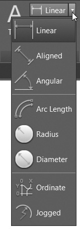
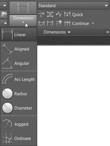
The most common dimension tools are located on the Dimension flyout menu on the Annotation panel on the Home tab of the ribbon for easy access (see Figure 13-1). These same tools and most of the other dimension tools are located on the Dimensions panel on the Annotate tab of the ribbon (see Figure 13-2).
Types of Dimensions
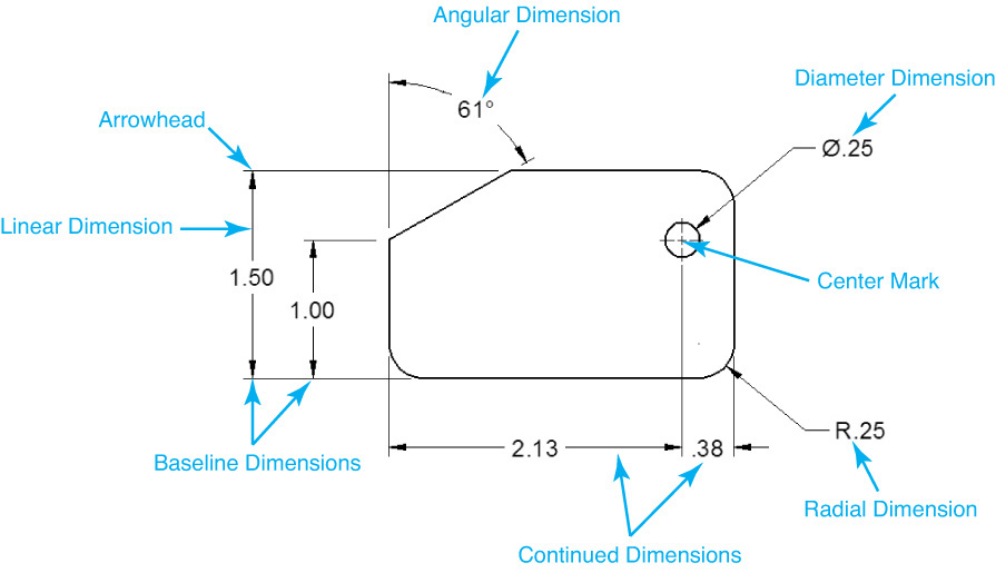
There are many types of dimension objects available in AutoCAD. Figure 13-3 shows some examples of the different types of dimension objects as well as some of the features found in a dimension object. The linear, radial, diameter, and angular dimensions are commonly used, but the type of dimensions you create will vary greatly based on your industry and discipline.
Note
Dimensions can be placed in either model space or layout (paper) space in AutoCAD. The decision of where to place dimensions (model or paper space) can be a hotly debated topic in the AutoCAD world. Regardless of how dimensioning is handled, the important thing is to maintain consistency among drawings for any given project. Your company’s CAD standards should provide clear guidelines for how dimensioning should be handled and where dimensions should be placed.
Dimension Associativity
In Chapter 2, you saw briefly how associativity works with dimensioning. Dimension objects are linked to the geometry and update automatically when the geometry changes. AutoCAD has different levels of associativity depending on a number of factors. Sometimes AutoCAD will “flake out” and association will be lost. When this happens, it is sometimes possible to manually reassociate dimensions using the REASSOCIATE command. Controlling dimension associativity is discussed later in this chapter.
Definition Points
When you place dimension objects, you first choose the type of dimension you want to create, and then either pick points or select an object to define the placement of the dimension object. Using either method, AutoCAD automatically creates point objects that define the distance. These defining points are called defpoints. AutoCAD measures the distance between these defpoints and uses that distance as the default dimension text. For example, to dimension a line, you create a linear dimension. AutoCAD places defpoints at each end of the line and measures the distance between those defpoints. You then choose a location for the placement of the dimension text.
defpoint: Point created when placing dimensions that defines the measurement value of the dimension.
Note
The Defpoints layer is unique in that it doesn’t plot, regardless of its Plot/Noplot layer setting. Also, once created, the Defpoints layer sometimes cannot be deleted with either the PURGE command or the Delete Layer button in the LAYER command.
When you create dimensions, AutoCAD automatically creates a layer called Defpoints. All defpoints are placed on the Defpoints layer.
Tip
If your drawing has a Defpoints layer, but no dimension objects, and you wish to get rid of the Defpoints layer but it will not purge, you can simply rename the layer. Once it is renamed, it will behave like any other layer and can be deleted or purged as needed.
Creating Horizontal and Vertical Dimensions
Vertical and horizontal dimensions are created with a single command, DIMLINEAR. The DIMLINEAR command measures the vertical or horizontal dimension between two definition points and allows you to pick the location of the dimension line.
Linear |
|
Ribbon & Panel: |
Home | Annotation
|
Menu: |
Dimension | Linear |
Command Line: |
DIMLINEAR |
Command Alias: |
DIMLIN |

Selecting Definition Points
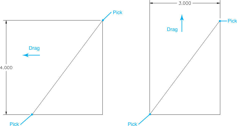
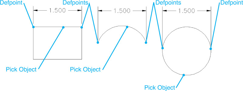
There are two ways to create a linear dimension: pick points or select an object. Using the pick point method, you select any two points in your drawing and then select the location of the dimension text. Where you place the dimension text determines whether a vertical or horizontal dimension is created. If you place the dimension text above or below the points, AutoCAD will create a horizontal dimension. Selecting to the left or right of the selected points will create a vertical dimension (see Figure 13-4).
Selecting an Object
You can also create a linear dimension by selecting a line, arc, or circle. When you start the DIMLINEAR command, AutoCAD prompts you to Specify first extension line origin or <select object>:. Press <Enter> to select a line, arc, or circle. When you select an object, AutoCAD will select the two points at the ends of the object as the definition points. Figure 13-5 shows the results of selecting different objects.
Note
When selecting an object, you can select only line, arc, or circle objects. Ellipses, text points, or spline curves are not allowed. When you select a polyline object, AutoCAD will dimension the line or arc segment of the polyline at the point you selected.
The DIMLINEAR Options
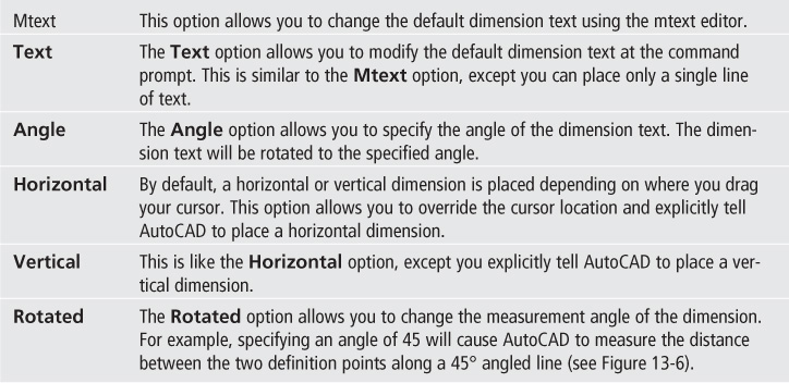
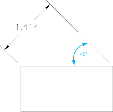
After you select the definition points, AutoCAD provides a number of options for creating and placing the dimensions. These options are listed below.
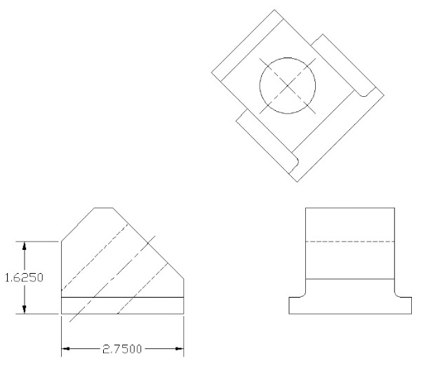
Exercise 13-1 Creating Linear Dimensions
![]() Open drawing EX13-1 in the student data files. Make sure object snaps are turned on and set to detect Endpoint and Center.
Open drawing EX13-1 in the student data files. Make sure object snaps are turned on and set to detect Endpoint and Center.
To access student data files, go to www.pearsondesigncentral.com.
![]() Start the DIMLINEAR command. AutoCAD prompts you to Specify first extension line origin or <select object>:.
Start the DIMLINEAR command. AutoCAD prompts you to Specify first extension line origin or <select object>:.
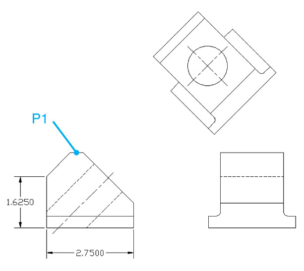
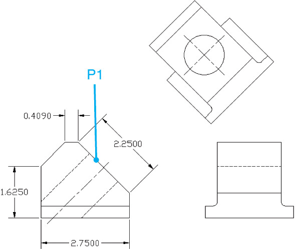
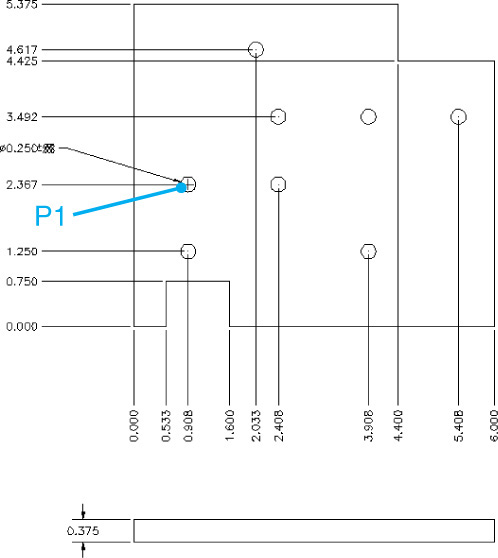
![]() Pick the endpoint P1 shown in Figure 13-7. AutoCAD prompts you to Specify second extension line origin:.
Pick the endpoint P1 shown in Figure 13-7. AutoCAD prompts you to Specify second extension line origin:.
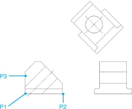
![]() Pick the endpoint P2 shown in Figure 13-7. AutoCAD prompts you to Specify dimension line location or
Pick the endpoint P2 shown in Figure 13-7. AutoCAD prompts you to Specify dimension line location or ![]() and starts dragging the dimension line.
and starts dragging the dimension line.
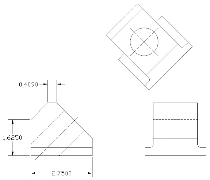
![]() Place the dimension line as shown in Figure 13-8. AutoCAD places the dimension and ends the DIMLINEAR command.
Place the dimension line as shown in Figure 13-8. AutoCAD places the dimension and ends the DIMLINEAR command.
![]() Restart the DIMLINEAR command. AutoCAD prompts you to Specify first extension line origin or <select object>:.
Restart the DIMLINEAR command. AutoCAD prompts you to Specify first extension line origin or <select object>:.
![]() Press <Enter>. AutoCAD prompts you to Select object to dimension.
Press <Enter>. AutoCAD prompts you to Select object to dimension.
![]() Pick the line at P3 shown in Figure 13-7. AutoCAD places the defpoints at the ends of the line and prompts you to Specify dimension line location or
Pick the line at P3 shown in Figure 13-7. AutoCAD places the defpoints at the ends of the line and prompts you to Specify dimension line location or ![]() .
.
![]() Place the dimension line as shown in Figure 13-8. AutoCAD places the dimension and ends the DIMLINEAR command.
Place the dimension line as shown in Figure 13-8. AutoCAD places the dimension and ends the DIMLINEAR command.
![]() Save your drawing as CH13_EXERCISE1. Your drawing should look like Figure 13-8.
Save your drawing as CH13_EXERCISE1. Your drawing should look like Figure 13-8.
Overriding Dimension Text
The DIMLINEAR command has two text options: Mtext and Text. These options allow you to override the default text associated with the dimension. By default, AutoCAD places the numerical distance between the two definition points as the dimension text. By using the Mtext and Text options, you can modify or even override the measured distance. For example, you may want to include a note or other additional text along with the default dimension, or you may want to type in a specific dimension instead of using the measured dimension value.
The <> Brackets
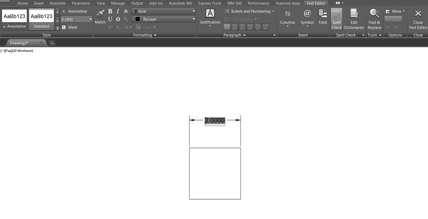
When you use the Mtext option, AutoCAD displays the multiline text editor with the default dimension text highlighted (see Figure 13-9). The default dimension text is the measured distance between the definition points. You can type any text before or after the default dimension text or you can delete it, but you cannot modify the value of the highlighted text. If you remove the default text, AutoCAD will ignore the measured distance and display only the text you specify.
Note
Just because you can overwrite dimension text doesn’t mean you should. When you overwrite the calculated dimension by either erasing or typing over the <> brackets, all dimension associativity is lost, so that if the drawing changes the dimension text remains the same and does not reflect the actual size of the object anymore. This situation should be avoided at all costs because eventually it will come back to haunt you.
If you delete the default dimension text, you can re-create it by typing <>. When AutoCAD sees the <> brackets, it will replace it with the measured distance between the definition points.
You can use the <> brackets with the Text option as well. When you use the Text option, AutoCAD will display the measured dimension as a default and allow you to type a single line of text. You can type whatever text you want, using the <> brackets as a placeholder for the measured distance between the definition points.
Tip
You can also use the DDEDIT command to edit dimension text. Even easier, you can type in ED to use its command alias.
Exercise 13-2 Modifying Dimension Text
![]() Continue from Exercise 13-1.
Continue from Exercise 13-1.
![]() Start the DIMLINEAR command. AutoCAD prompts you to Specify first extension line origin or <select object>:.
Start the DIMLINEAR command. AutoCAD prompts you to Specify first extension line origin or <select object>:.
![]() Press <Enter>. AutoCAD prompts you to Select object to dimension.
Press <Enter>. AutoCAD prompts you to Select object to dimension.
![]() Pick the line at P1 shown in Figure 13-10. AutoCAD places the defpoints at the ends of the line and prompts you to Specify dimension line location or
Pick the line at P1 shown in Figure 13-10. AutoCAD places the defpoints at the ends of the line and prompts you to Specify dimension line location or ![]() .
.
![]() Choose the Mtext option. AutoCAD displays the multiline text editor with the default dimension text highlighted. Delete the default dimension text, and type 1.00 in the mtext editor. Close the mtext editor. AutoCAD shows the dimension as 1.00.
Choose the Mtext option. AutoCAD displays the multiline text editor with the default dimension text highlighted. Delete the default dimension text, and type 1.00 in the mtext editor. Close the mtext editor. AutoCAD shows the dimension as 1.00.
![]() Select the line you just dimensioned to activate its grips. Select the grip at one endpoint, and drag it to a new location. Pick anywhere on the screen to place the end of the line. AutoCAD stretches the line, and the dimension moves along with it, but the value of the dimension text does not update.
Select the line you just dimensioned to activate its grips. Select the grip at one endpoint, and drag it to a new location. Pick anywhere on the screen to place the end of the line. AutoCAD stretches the line, and the dimension moves along with it, but the value of the dimension text does not update.
![]() Start the DDEDIT command and select the 1.00 dimension text. Delete the 1.00 text and type <>. AutoCAD replaces the <> brackets with the measured length of the line.
Start the DDEDIT command and select the 1.00 dimension text. Delete the 1.00 text and type <>. AutoCAD replaces the <> brackets with the measured length of the line.
![]() Select the line to activate its grips, and return the endpoint to its original location. AutoCAD stretches the line, and the dimension moves with it. The dimension text updates to show the change.
Select the line to activate its grips, and return the endpoint to its original location. AutoCAD stretches the line, and the dimension moves with it. The dimension text updates to show the change.
![]() Save your drawing. Your drawing should look like Figure 13-11.
Save your drawing. Your drawing should look like Figure 13-11.
Creating Aligned Dimensions
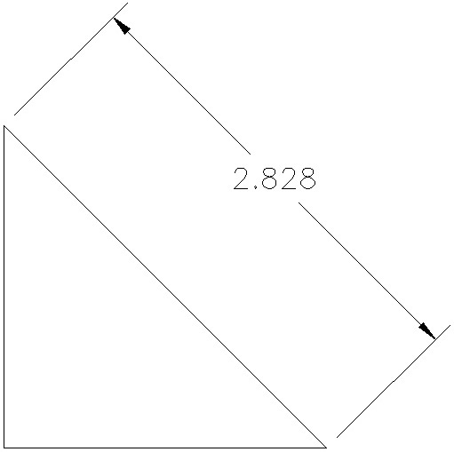
An aligned dimension is another type of linear dimension. However, although horizontal and vertical dimensions measure distances along either the X- or Y-axis, respectively, an aligned dimension measures the true distance between any two points. The dimension text is placed parallel to a line between the two points (see Figure 13-12). Aligned dimensions are created with the DIMALIGNED command.
Aligned |
|
Ribbon & Panel: |
Home | Annotation
|
Menu: |
Dimension | Aligned |
Command Line: |
DIMALIGNED |
Command Alias: |
DIMALI |

When using the DIMALIGNED command, you can select the two definition points, or you can select a line, arc, or circle. Once you specify the definition points, the Mtext, Text, and Angle options are available. These options are identical to the Mtext, Text, and Angle options in the DIMLINEAR command.
Exercise 13-3 Creating Aligned Dimensions
![]() Continue from Exercise 13-2.
Continue from Exercise 13-2.
![]() Start the DIMALIGNED command. AutoCAD prompts you to Specify first extension line origin or <select object>:.
Start the DIMALIGNED command. AutoCAD prompts you to Specify first extension line origin or <select object>:.
![]() Press <Enter>. AutoCAD prompts you to Select object to dimension.
Press <Enter>. AutoCAD prompts you to Select object to dimension.
![]() Pick the line at P1 shown in Figure 13-13. AutoCAD places the defpoints at the ends of the line and prompts you to Specify dimension line location or
Pick the line at P1 shown in Figure 13-13. AutoCAD places the defpoints at the ends of the line and prompts you to Specify dimension line location or ![]() .
.
![]() Place the dimension line as shown in Figure 13-13.
Place the dimension line as shown in Figure 13-13.
![]() Save your drawing. Your drawing should look like Figure 13-13.
Save your drawing. Your drawing should look like Figure 13-13.
Tip
You can also select the extension line origin points to define the angle of the aligned dimension. Typically, you would rely on object snaps to snap to endpoints or intersections.
Dimensioning Circles and Arcs
When dimensioning circles and arcs, you will typically be calling out either radius or diameter dimensions or, in the case of arcs, the length of an arc segment. AutoCAD provides a dimensioning command for each of these types of dimensions.
Radius |
|
Ribbon & Panel: |
Home | Annotation
|
Menu: |
Dimension | Radius |
Command Line: |
DIMRADIUS |
Command Alias: |
DIMRAD |

Radius Dimension
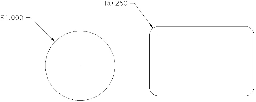
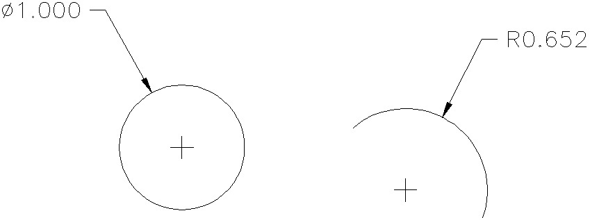
Radius dimensions are placed with the DIMRADIUS command. When you select this command, AutoCAD will prompt you to select an arc or circle. You can select circles, arcs, and polyline arc segments. Once you select an arc or circle, AutoCAD measures the radius of the arc and prompts you for the location of the text. You can place the text inside or outside the arc. AutoCAD will place a leader line perpendicular to the arc through the specified point on the arc and put a center mark in the center of the circle or arc. When you place the text, AutoCAD will automatically place an R prefix before the measured radius (see Figure 13-14). As with the DIMLINEAR and DIMALIGNED commands, you have the Mtext, Text, and Angle options for modifying the dimension text.
Jogged |
|
Ribbon & Panel: |
Home | Annotation
|
Menu: |
Dimension | Jogged |
Command Line: |
DIMJOGGED |
Command Alias: |
JOG |

Creating a Jogged Radius Dimension
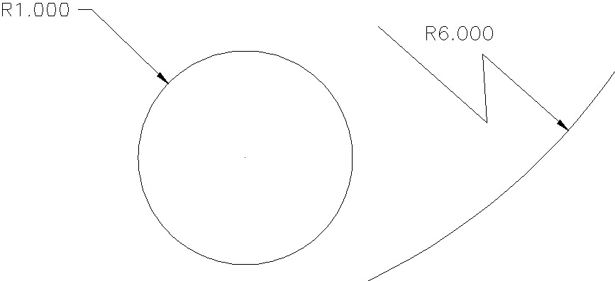
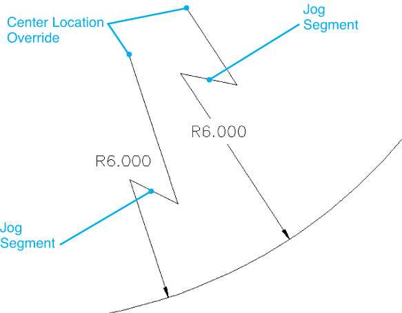
With the DIMRADIUS command, the leader line will always point perpendicular to the circle or arc segment. The start point of the leader will always be in line with the center point of the arc (see Figure 13-15). A jogged radius dimension is similar to a regular radius dimension except the leader line has an offset jog built into it. This allows you to specify a different center point for the leader. This can be useful when dimensioning large radii in which the center point lies outside your drawing area. Jogged radius dimensions are created with the DIMJOGGED command.
When you start the DIMJOGGED command, you are prompted to select a circle or arc. Once you select an object, AutoCAD prompts you to Specify center location override:. This is the location of the starting point (nonarrow end) of the leader line. The leader line is drawn from this point to a point on the circle or arc segment. You are then prompted for the location of the dimension text. Once you place the text, you can adjust the location of the jogged segment (see Figure 13-16).
Diameter |
|
Ribbon & Panel: |
Home | Annotation
|
Menu: |
Dimension | Diameter |
Command Line: |
DIMDIAMETER |
Command Alias: |
DIMDIA |

Diameter Dimension
Diameter dimensions are placed with the DIMDIAMETER command. The DIMDIAMETER command behaves just like the DIMRADIUS command. The only difference is that text shown is the diameter of the arc or circle, and AutoCAD places the diameter symbol Ø in front of the text.
It is possible to dimension an arc beyond its endpoints. AutoCAD automatically creates an arc extension line.
Exercise 13-4 Creating Radius and Diameter Dimensions
![]() Continue from Exercise 13-3.
Continue from Exercise 13-3.
![]() Start the DIMRADIUS command. AutoCAD prompts you to Select arc or circle:.
Start the DIMRADIUS command. AutoCAD prompts you to Select arc or circle:.
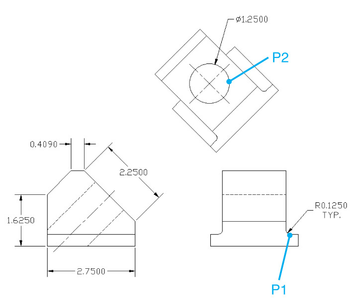
![]() Pick the arc at P1 shown in Figure 13-17. AutoCAD places the defpoints at the center of the arc and at the point you selected on the arc. You are then prompted to Specify dimension line location or
Pick the arc at P1 shown in Figure 13-17. AutoCAD places the defpoints at the center of the arc and at the point you selected on the arc. You are then prompted to Specify dimension line location or ![]() .
.
![]() Choose the Mtext option and type TYP. after the default dimension text. Close the mtext editor.
Choose the Mtext option and type TYP. after the default dimension text. Close the mtext editor.
![]() Place the dimension line as shown in Figure 13-17.
Place the dimension line as shown in Figure 13-17.
![]() Start the DIMDIAMETER command. AutoCAD prompts you to Select arc or circle:.
Start the DIMDIAMETER command. AutoCAD prompts you to Select arc or circle:.
![]() Pick the circle at P2 shown in Figure 13-17. AutoCAD places the defpoints at the center of the arc and at the point you selected on the circle. You are then prompted to Specify dimension line location or
Pick the circle at P2 shown in Figure 13-17. AutoCAD places the defpoints at the center of the arc and at the point you selected on the circle. You are then prompted to Specify dimension line location or ![]() .
.
![]() Place the dimension line as shown in Figure 13-17.
Place the dimension line as shown in Figure 13-17.
![]() Save your drawing. Your drawing should look like Figure 13-17.
Save your drawing. Your drawing should look like Figure 13-17.
Dimensioning the Length of an Arc
Similar to a linear dimension, AutoCAD can dimension the length of an arc using the DIMARC command. When using the DIMARC command, you select an arc segment, and AutoCAD measures the distance along the arc. By default, AutoCAD will dimension the entire length of the arc from endpoint to endpoint, but you can also opt to dimension a portion of the arc length. In addition to the Mtext, Text, and Angle options, the Partial option allows you to pick a start and endpoint along the arc segment and dimension only the portion of the arc between the two points.
Arc Length |
|
Ribbon & Panel: |
Home | Annotation
|
Menu: |
Dimension | Arc Length |
Command Line: |
DIMARC |
Command Alias: |
None |

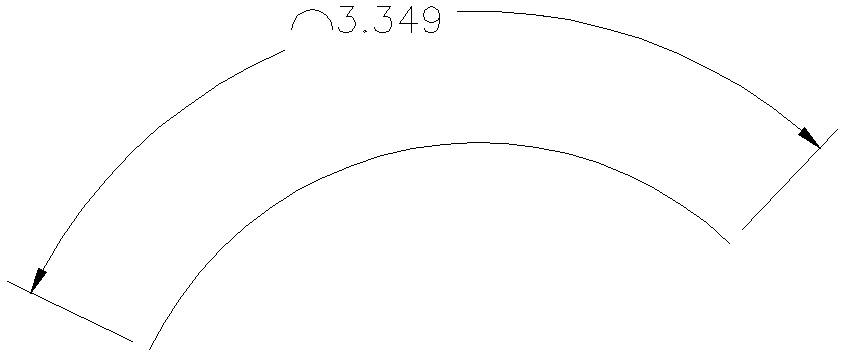
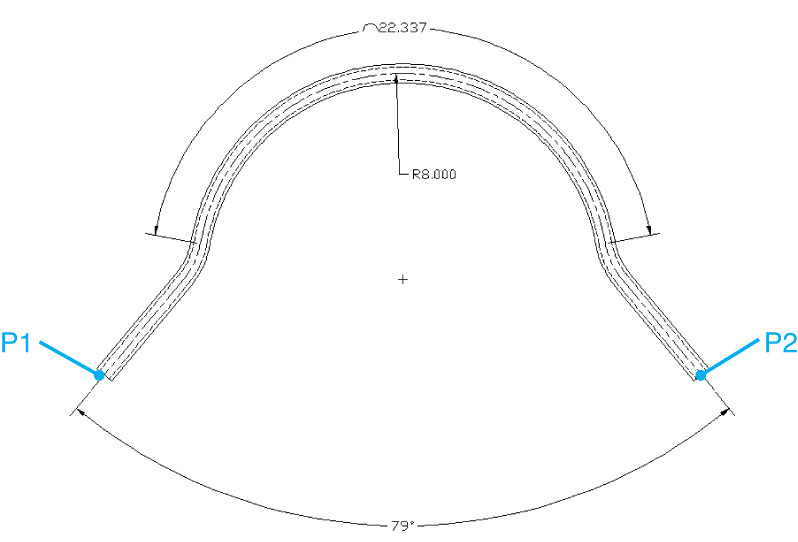
When you place an arc length dimension, AutoCAD automatically places the arc symbol ∩ in front of the dimension value (see Figure 13-18).
Exercise 13-5 Creating an Arc Length Dimension
![]() Open drawing EX13-5 in the student data files.
Open drawing EX13-5 in the student data files.
To access student data files, go to www.pearsondesigncentral.com.
![]() Start the DIMARC command. AutoCAD prompts you to Select arc or polyline arc segment:.
Start the DIMARC command. AutoCAD prompts you to Select arc or polyline arc segment:.
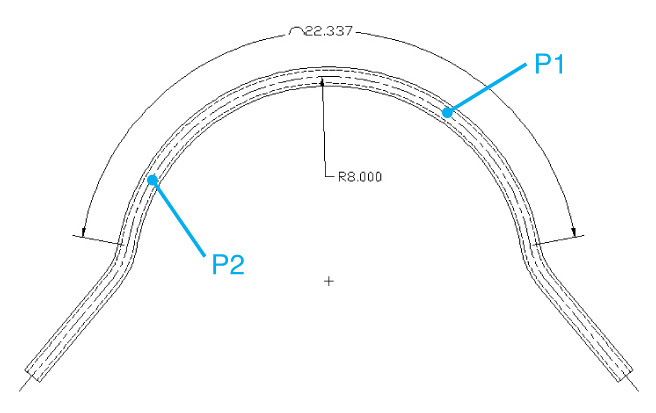
![]() Pick the arc at P1 shown in Figure 13-19. AutoCAD places the defpoints at the center of the arc and at the point you selected on the arc. You are then prompted to Specify dimension line location or
Pick the arc at P1 shown in Figure 13-19. AutoCAD places the defpoints at the center of the arc and at the point you selected on the arc. You are then prompted to Specify dimension line location or ![]() .
.
![]() Place the dimension line as shown in Figure 13-19.
Place the dimension line as shown in Figure 13-19.
![]() Start the DIMRADIUS command. AutoCAD prompts you to Select arc or circle:.
Start the DIMRADIUS command. AutoCAD prompts you to Select arc or circle:.
![]() Pick the arc at P2 shown in Figure 13-19. You are prompted to Specify arc length dimension location or
Pick the arc at P2 shown in Figure 13-19. You are prompted to Specify arc length dimension location or ![]() .
.
![]() Place the dimension line as shown in Figure 13-19.
Place the dimension line as shown in Figure 13-19.
![]() Save your drawing as CH13_EXERCISE5. Your drawing should look like Figure 13-19.
Save your drawing as CH13_EXERCISE5. Your drawing should look like Figure 13-19.
Creating Center Marks
When dimensioning arcs and circles, AutoCAD places marks at the center of the dimensions (see Figure 13-20). You may have a need to place center marks on arcs and circles that are not dimensioned. AutoCAD has a number of ways to create center marks. One option is to simply draw center marks using either the LINE or PLINE command. Another way is to use the DIMCENTER command.
Center Mark |
|
Ribbon & Panel: |
Annotate | Dimensions
|
Menu: |
Dimension | Center Mark |
Command Line: |
DIMCENTER |
Command Alias: |
None |

Note
When you use the DIMCENTER command, the resulting lines are not dimension objects but simply line segments.
The DIMCENTER command places orthogonal line segments at the center of a circle or arc segment. When you start the DIMCENTER command, AutoCAD prompts you to select a circle or an arc segment and then places center mark line segments.
Angular |
|
Ribbon & Panel: |
Home | Annotation
|
Pull-down Menu: |
Dimension | Angular |
Command Line: |
DIMANGULAR |
Command Alias: |
DIMANG |

For More Details
The DIMCEN system variable controls the size of center marks. Dimension variables are typically controlled through dimension styles, which are covered later in this chapter. For more information on the DIMCEN system variable, see Appendix D.
Angular Dimensions
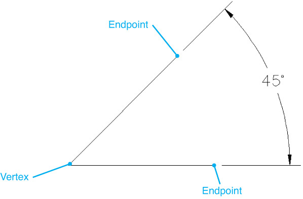
With linear dimensions, AutoCAD needs to have two definition points in order to calculate the dimension value. With radius and diameter dimensions, AutoCAD can calculate the dimension value directly from the arcs and circles. When dimensioning angles, AutoCAD needs to know three points in order to define the angular dimension: a center vertex and two endpoints (see Figure 13-21). Angular dimensions are placed with the DIMANGULAR command. When using this command, you have three options for defining angular dimension: selecting an arc or circle, selecting two intersecting lines, or picking three points to define the vertex and the two endpoints.
Selecting Objects
When you start the DIMANGULAR command, AutoCAD prompts you to Select arc, circle, line, or <specify vertex>. If you select an arc, AutoCAD uses the center and ends of the arc to determine the angular dimensions.
If you select a circle, AutoCAD uses the selection point as one endpoint of the angle and the center of the circle as the vertex. AutoCAD then prompts you for a second endpoint and allows you to place the dimension text.
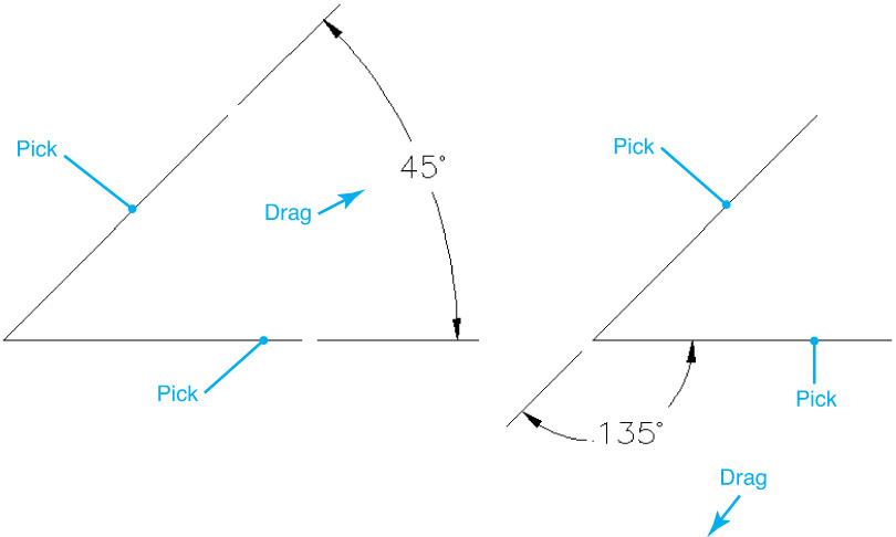
If you select a line segment, AutoCAD will ask you to select another line segment and will dimension the angle between endpoints of the first and second lines. AutoCAD will use the endpoints closest to the selection point of the line. Figure 13-22 shows the results of selecting two lines at various points.
Selecting Vertex and Angle Endpoints
To specify the vertex and angle endpoints, press <Enter> when AutoCAD prompts you to Select arc, circle, line, or <specify vertex>. AutoCAD will prompt you for a vertex point and then prompt you for two endpoints.
The Quadrant Option
The Quadrant option allows you to place dimension text outside of the angle being measured. The only way to access the Quadrant option is from the right-click menu after selecting the angle to measure when AutoCAD prompts you: Specify dimension arc line location or ![]() .
.
The Quadrant option prompts you to specify the quadrant that you want to dimension separate from specifying the dimension arc line location. If the dimension arc line is outside of the quadrant that is being measured, AutoCAD automatically creates an arc extension line using the current extension line settings.
Exercise 13-6 Creating an Angular Dimension
![]() Continue from Exercise 13-5.
Continue from Exercise 13-5.
![]() Start the DIMANGULAR command. AutoCAD prompts you to Select arc, circle, line, or <specify vertex>.
Start the DIMANGULAR command. AutoCAD prompts you to Select arc, circle, line, or <specify vertex>.
![]() Pick the line at P1 shown in Figure 13-23. AutoCAD prompts you to Select second line:.
Pick the line at P1 shown in Figure 13-23. AutoCAD prompts you to Select second line:.
![]() Pick the line at P2 shown in Figure 13-23. AutoCAD prompts you to Specify dimension arc line location or
Pick the line at P2 shown in Figure 13-23. AutoCAD prompts you to Specify dimension arc line location or ![]() .
.
![]() Place the dimension line as shown in Figure 13-23. Notice that the angle that is dimensioned varies with your cursor location.
Place the dimension line as shown in Figure 13-23. Notice that the angle that is dimensioned varies with your cursor location.
![]() Save your drawing. Your drawing should look like Figure 13-23.
Save your drawing. Your drawing should look like Figure 13-23.
Note
If you select two parallel lines, AutoCAD will show you the message Lines are parallel in the command line and end the command. If you select anything but a line segment for the second line, AutoCAD will display the message Object selected is not a line in the command line and prompt you to Select second line.
Creating Datum and Chain Dimensions
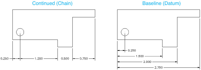
Datum and chain dimensioning refers to linear dimensions that share common extension lines. A datum dimension is also known as a baseline dimension, in which multiple features are measured from a common feature. Chain dimensions are also known as continued dimensions, in which linear dimensions continue end to end. Figure 13-24 shows examples of continued and baseline dimensions.
Continued Dimension
A continued dimension is similar to a baseline dimension. It requires an existing linear or angular dimension, and it allows you to place multiple dimension lines in a single command. The only difference is that while baseline dimensions measure dimensions from a common extension line, continued dimensions measure from the last placed dimension line. The result is a chain of dimensions, each one measured from the last. Continued (or chain) dimensions are created with the DIMCONTINUE command.
Continue |
|
Ribbon & Panel: |
Annotate | Dimensions
|
Menu: |
Dimension | Continue |
Command Line: |
DIMCONTINUE |
Command Alias: |
DIMCONT |

When you start the DIMCONTINUE command, AutoCAD will place the dimension line at the second extension line of the last linear or angular dimension placed in the drawing. If you want to continue the dimension from dimension, you can press <Enter> to select a different extension line. Like the DIMBASELINE command, the DIMCONTINUE command will repeat until you end the command. You also have the Undo and Select options to undo the last continued dimension or to select a different extension line to continue from.
Baseline Dimension
Baseline dimensions are measured from an extension line of an existing linear or angular dimension. When you place a baseline dimension, each dimension is measured from this extension line, and the dimension lines are spaced at a predefined distance. Baseline dimensions are created with the DIMBASELINE command.
Baseline |
|
Ribbon & Panel: |
Annotate | Dimensions
|
Menu: |
Dimension | Baseline |
Command Line: |
DIMBASELINE |
Command Alias: |
DIMBASE |

For More Details
The DIMDLI system variable controls the spacing of the baseline dimension lines. Dimension variables are typically controlled through dimension styles, which are covered later in this chapter. For more information on the DIMDLI system variable, see Appendix D.
The DIMBASELINE command requires an existing linear or angular dimension. By default, AutoCAD will use the first extension line of the last linear or angular dimension as the baseline. If you want to use a different extension line, you can press <Enter> to select a different extension line. If AutoCAD cannot locate or determine where the last dimension line is, it will prompt you to select an extension line to use for the baseline.
Once you’ve specified the extension line to use as the baseline, AutoCAD prompts you to pick a definition point for the next extension line. The DIMBASELINE command will continue to place baseline dimensions until you end the command. While placing baseline dimensions, you can use the Undo option to undo a dimension line placement or press <Enter> to select a different extension baseline.
Exercise 13-7 Creating Continued and Baseline Dimensions
![]() Open drawing EX13-7 in the student data files.
Open drawing EX13-7 in the student data files.
To access student data files, go to www.pearsondesigncentral.com.
![]() Start the DIMLINEAR command and place the horizontal dimension between P1 and P2 as shown in Figure 13-25.
Start the DIMLINEAR command and place the horizontal dimension between P1 and P2 as shown in Figure 13-25.
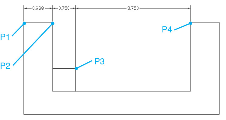
![]() Start the DIMCONTINUE command. AutoCAD starts dragging a dimension from the previous dimension. You are prompted to Specify a second extension line origin or
Start the DIMCONTINUE command. AutoCAD starts dragging a dimension from the previous dimension. You are prompted to Specify a second extension line origin or ![]() .
.
![]() Place the dimensions P3 and P4 as shown in Figure 13-25. Press <Esc> to exit the DIMCONTINUE command.
Place the dimensions P3 and P4 as shown in Figure 13-25. Press <Esc> to exit the DIMCONTINUE command.
![]() Start the DIMBASELINE command. AutoCAD starts dragging a dimension from the previous dimension. You are prompted to Specify a second extension line origin or
Start the DIMBASELINE command. AutoCAD starts dragging a dimension from the previous dimension. You are prompted to Specify a second extension line origin or ![]() .
.
![]() Press <Enter> to choose the Select option. AutoCAD prompts you to Select base dimension:.
Press <Enter> to choose the Select option. AutoCAD prompts you to Select base dimension:.
![]() Choose the extension line at P1 shown in Figure 13-26. AutoCAD prompts you to Specify a second extension line origin or
Choose the extension line at P1 shown in Figure 13-26. AutoCAD prompts you to Specify a second extension line origin or ![]() .
.
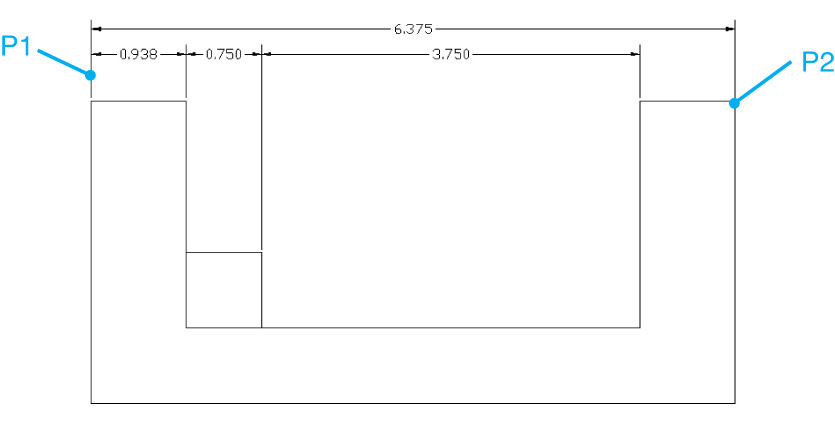
![]() Select the end of the line at point P2 shown in Figure 13-26. AutoCAD automatically spaces the dimension above the selected dimension.
Select the end of the line at point P2 shown in Figure 13-26. AutoCAD automatically spaces the dimension above the selected dimension.
![]() Save your drawing as CH13_EXERCISE7. Your drawing should look like Figure 13-26.
Save your drawing as CH13_EXERCISE7. Your drawing should look like Figure 13-26.
DIMASSOC System Variable
There are actually three levels of associativity for a dimension object. The DIMASSOC system variable controls which level of dimension associativity AutoCAD uses.
The DIMASSOC system variable can be set to a value of 0, 1, or 2. When set to 2 (the default setting), dimension defpoints are associated with objects in the drawing. For example, if you dimension between the two endpoints of a line, AutoCAD will create defpoints at the endpoints of the line, and these defpoints will be associated with the line object. If the line moves, the dimension will move along with it. If an endpoint of the line is moved (stretched, trimmed, extended, etc.), the defpoint associated with that endpoint will move, and the dimension will update.
When DIMASSOC is set to 1, AutoCAD still creates associative dimensions, but the defpoints are not associated with any particular geometry. To update a dimension, you must modify (move or stretch) the defpoints associated with the dimension explicitly. For example, if you dimension a line with DIMASSOC set to 1, AutoCAD will create defpoints at the ends of the line. But if you move the line, the dimension will not follow it. You would have to select and move the dimension along with the line to keep them together. If you move the end of the line (by stretching, trimming, extending, etc.), you will need to move the defpoint located at the end of the line as well in order for the dimension to update.
When DIMASSOC is set to 0, AutoCAD creates exploded dimensions with no associativity. No defpoints are created, and each part of the dimension is created as a separate object (lines and text).
Tip
Although it’s possible to create exploded dimensions, it’s considered bad practice in most CAD work environments. Exploded dimensions are difficult to manage and update and can lead to sloppy and inaccurate drawings.
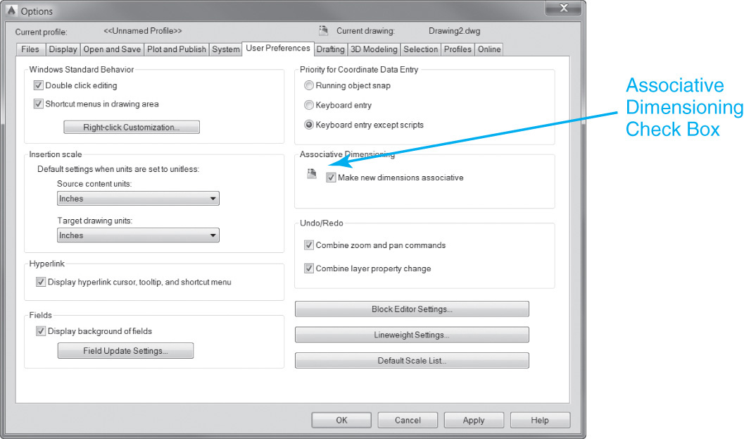
You can toggle the DIMASSOC variable with the Associative Dimensioning check box in the User Preferences tab of the Options dialog box (see Figure 13-27). When this box is checked, DIMASSOC is set to 2. With the check removed, DIMASSOC is set to 1.
Dimension Tools
AutoCAD provides a few handy dimension tools that allow you to automate tasks that used to be much more time-consuming. There are tools to evenly space stacked dimensions and to break dimension lines and extension lines that cross other dimensions, as well as that have the ability to create jog lines in linear dimensions when a distance is too long to fit on the specified sheet size.
Adjust Space |
|
Ribbon & Panel: |
Annotate | Dimensions
|
Menu: |
Dimension | Dimension Space |
Command Line: |
DIMSPACE |
Command Alias: |
None |

The Adjust Space Tool
The Adjust Space tool allows you to evenly space selected dimensions as shown in Figure 13-28. You can specify the spacing distance between dimension lines or let AutoCAD automatically determine a minimum spacing distance.
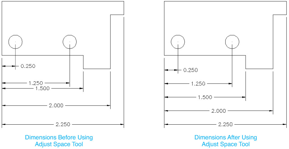
When you select the Adjust Space tool, AutoCAD prompts you to Select the base dimension: so that you can select the first dimension in the stack. After selecting a base dimension, AutoCAD then prompts you to Select dimensions to space:. Select the dimensions you want to space, and either enter a distance or press <Enter> to select the Auto option. The Auto option automatically spaces the dimensions based on the current dimension text height.
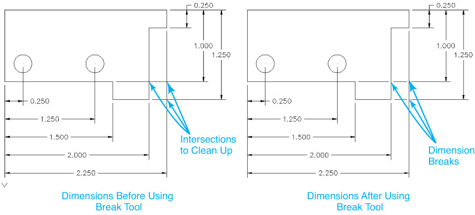
The Break Tool
The Break tool allows you to break dimension or extension lines where they intersect other dimensions or objects in your drawing as shown in Figure 13-29.
Break |
|
Ribbon & Panel: |
Annotate | Dimensions
|
Menu: |
Dimension | Dimension Break |
Command Line: |
DIMBREAK |
Command Alias: |
None |

Note
When you break a dimension either by selecting objects or by using the Auto option, the breaks will automatically update when the intersection point moves. If the objects are moved so that they no longer intersect, the break will disappear; if they are moved back, the break will automatically return to the original location.
When you select the Break tool, AutoCAD prompts you to Select dimension to add/remove break or ![]() so that you can select the dimension. After selecting the dimension, you have four options:
so that you can select the dimension. After selecting the dimension, you have four options:
• Select intersecting objects to use as cutting edges for the break. AutoCAD prompts for objects until you press <Enter>
• Use the Auto option to automatically trim around all intersecting objects
• Use the Manual option so that you have to manually pick break points
• Use the Remove option to remove all the breaks from selected dimensions or leaders
Tip
You can break more than one dimension at a time by selecting the Multiple option after the Break tool.
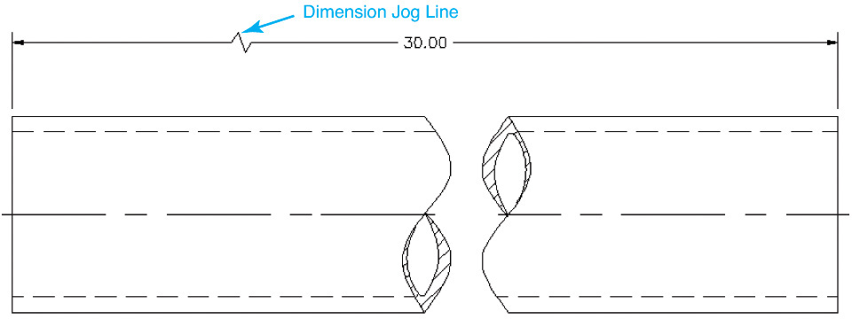
The Jog Line Tool
The Jog Line tool allows you to add a jog, or breakline, to linear dimensions to represent measurements whose values are not the same length as the dimension line. Jogged dimension lines are typically used when a sheet is too small to display the true length of a dimension line as shown in Figure 13-30.
Jog Line |
|
Ribbon & Panel: |
Annotate | Dimensions
|
Menu: |
Dimension | Jogged Linear |
Command Line: |
DIMJOGLINE |
Command Alias: |
None |

Note
The linear jog size can be specified on the Symbols and Arrows tab of the Modify Dimension Style dialog box explained later. The default is 1.5 × text height.
When you select the Jog Line tool, AutoCAD prompts you to Select dimension to add jog or ![]() so that you can select the dimension to add the jog. After selecting a dimension, AutoCAD then prompts you to Specify jog location (or press Enter):. You can either pick the location on the dimension line to locate the jog line or press <Enter> to place the jog line automatically based on the direction of the dimension definition points. The jog line is created closest to the first dimension definition point.
so that you can select the dimension to add the jog. After selecting a dimension, AutoCAD then prompts you to Specify jog location (or press Enter):. You can either pick the location on the dimension line to locate the jog line or press <Enter> to place the jog line automatically based on the direction of the dimension definition points. The jog line is created closest to the first dimension definition point.
You can change the jog location using grips. You can turn off a jog line or edit its height using the Properties palette.
Quick Dimensioning
When creating dimension objects, you may find that placing dimensions can be a somewhat tedious, repetitive process. Many times you may wish to simply place some dimensions on the drawing and then go back and adjust their placement and orientation to suit your drawing. AutoCAD helps automate the process of placing dimensions by allowing you to create multiple dimensions at once. The QDIM command (quick dimension) allows you to select multiple objects and then select a type of dimension to place. AutoCAD will then automatically detect definition points and place the specified dimensions based on those points.
Quick Dimension
When you start the QDIM command, AutoCAD will prompt you to Select geometry to dimension:. Once you have built your selection set of objects, press <Enter>, and AutoCAD will provide a number of options. These options are described below.
Quick Dimension |
|
Ribbon & Panel: |
Annotate | Dimensions
|
Menu: |
Dimension | Quick Dimension |
Command Line: |
QDIM |
Command Alias: |
None |

Continuous
The Continuous option places continuous dimensions from the outermost points of the selected geometry. When you select this option, AutoCAD will place the dimension objects and allow you to select a placement point for the dimensions. The dimensions will be either vertical or horizontal based on where you drag your cursor.
Staggered
The Staggered option places a series of staggered or nested linear dimensions, starting from the innermost pair of definition points. From there, it will place a linear dimension on the next outer level of points and continue outward until the geometry is dimensioned. Figure 13-31 shows some examples of staggered dimensions placed with the QDIM command.
datumpoint
The datumPoint option sets a base point for the Baseline and Ordinate dimension options. By default, when you use the Baseline option, it places the datum or base point of the dimensions on the definition point nearest to 0,0. The datumPoint option allows you to override this and place the datum point at any point in the drawing.
Baseline
The Baseline option creates a series of baseline dimensions starting either at 0,0 or at the point specified with the datumPoint option. Figure 13-32 shows you some examples of baseline dimensions.
Ordinate
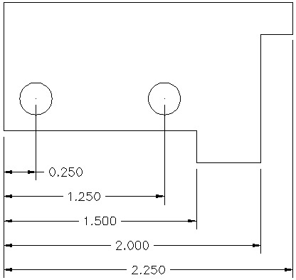
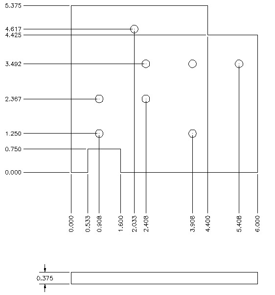
Ordinate dimensioning displays X- and Y-datum coordinates based on an origin, or datum point. The datum point is typically located at a key point on the geometry such as the corner of a part. The Ordinate option of the QDIM command creates a set of ordinate dimensions with the origin being either 0,0 or a point specified with the datumPoint option.
Tip
Ordinate dimensions can also be created with the DIMORDINATE command. However, the DIMORDINATE command does not allow you to set a 0,0 datum point. To use the DIMORDINATE command, you must first establish a user coordinate system (UCS) with its origin located at your desired datum point, which is beyond the scope of this text. Using the QDIM command with the datumPoint and Ordinate options is a much quicker way of creating ordinate dimensions.
Radius
The Radius option will search through your selection of objects and find any circles or arcs. You are then prompted for a location for the leaders. The leaders are placed in the same relative position on each arc or circle. Figure 13-33 shows an example of using the Radius option.
Diameter
The Diameter option works the same way as the Radius option. AutoCAD places diameter dimensions at the same relative points on each arc or circle.
Edit
The Edit option allows you to edit the definition points within the selection set. When you choose this option, AutoCAD will show you all the definition points found in the selection set. You can add or delete definition points prior to placing your dimensions.
seTtings
The seTtings option allows you to set the preference for determining definition points. By default, AutoCAD will look for endpoints of objects. You can set it to Intersection or Endpoint.
Exercise 13-8 Creating Quick Dimensions
![]() Open drawing EX13-8 in the student data files.
Open drawing EX13-8 in the student data files.
To access student data files, go to www.pearsondesigncentral.com.
![]() Start the QDIM command. AutoCAD prompts you to Select geometry to dimension:.
Start the QDIM command. AutoCAD prompts you to Select geometry to dimension:.
![]() Type ALL<Enter> to select all the geometry in the drawing. AutoCAD prompts you to Specify dimension line position or
Type ALL<Enter> to select all the geometry in the drawing. AutoCAD prompts you to Specify dimension line position or ![]() .
.
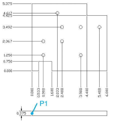
![]() Choose the datumPoint option and pick the endpoint P1 shown in Figure 13-34. AutoCAD prompts you to Specify dimension line position or
Choose the datumPoint option and pick the endpoint P1 shown in Figure 13-34. AutoCAD prompts you to Specify dimension line position or ![]() .
.
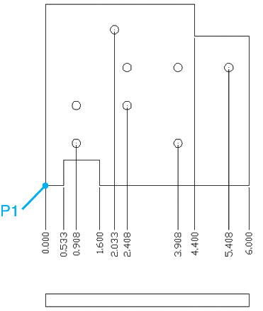
![]() Choose the Ordinate option. AutoCAD prompts you to Specify dimension line position or
Choose the Ordinate option. AutoCAD prompts you to Specify dimension line position or ![]() .
.
![]() Place the X-datum dimensions as shown in Figure 13-34. AutoCAD prompts you to Specify dimension line position or
Place the X-datum dimensions as shown in Figure 13-34. AutoCAD prompts you to Specify dimension line position or ![]() .
.
![]() Restart the QDIM command. AutoCAD defaults to the Ordinate option. Place the Y-datum dimensions shown in Figure 13-35.
Restart the QDIM command. AutoCAD defaults to the Ordinate option. Place the Y-datum dimensions shown in Figure 13-35.
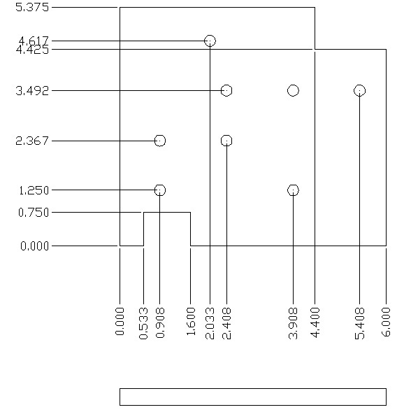
![]() Save your drawing as CH13_EXERCISE8. Your drawing should look like Figure 13-35.
Save your drawing as CH13_EXERCISE8. Your drawing should look like Figure 13-35.
Managing Dimension Styles
So far, we’ve looked at how to create and place dimension objects. Creating and placing dimension objects is only part of the process. In this section, you’ll examine how to control the look of dimension objects through dimension styles.
Dimension Style |
|
Ribbon & Panel: |
Home | Annotation
|
Menu| |
Dimension | Dimension Style... |
Command Line: |
DIMSTYLE |
Command Alias: |
DDIM |

A dimension style is a collection of dimension settings that is assigned a name and is applied as a group to dimension objects. Dimension styles control the look and behavior of dimension objects, such as the type of arrowhead used, the text style used in the dimensions, tolerance values and formatting, and the overall scale of the dimension.
Dimension styles work similarly to text styles or layers: you set a dimension style current and then any new objects are created using the settings contained within that style. Dimension styles are managed with the DIMSTYLE command.
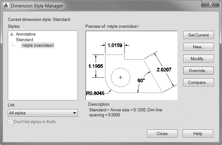
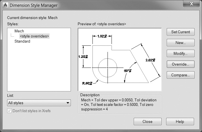
When you start the DIMSTYLE command, AutoCAD displays the Dimension Style Manager dialog box (see Figure 13-36). From this dialog box, you can create dimension styles, modify dimension styles, compare dimension styles, and set a dimension style current. The Styles: list shows dimension styles defined in your drawing. The List options allow you to control which dimension styles are shown in the Styles: list. You can choose to show all dimension styles or only the ones currently used in the drawing. You can also choose to show or hide dimension styles contained in referenced drawings.
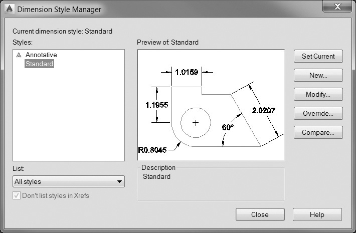
The Preview area shows a preview image of the current dimension style and tells you which dimension style is current. The buttons along the right-hand side of the dialog box allow you to create, modify, override, and compare dimension styles.
Creating a Dimension Style
AutoCAD comes with two predefined dimension styles: Annotative and Standard. Standard is AutoCAD’s default dimension style. Both can be modified, renamed, or even deleted if one is not the current style. The settings for the dimension styles are defined in the template file used to create the drawing. To create a new dimension style, choose the New... button. AutoCAD will display the Create New Dimension Style dialog box (see Figure 13-37).
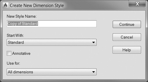
When you create a new dimension style, AutoCAD will create a copy of an existing dimension style as the starting point. In the Create New Dimension Style dialog box, you specify the name for the new dimension style and tell AutoCAD which style to copy as the starting point. You can also create a dimension style that applies only to a certain type of dimension. For example, you might want all your dimension text to align with the dimension line, except for radial and diameter dimensions, where you might want the text to be horizontal. These styles are known as child dimension styles and appear as a substyle of the parent dimension style.
Tip
When you select a child dimension style in the Dimension Style Manager dialog box, the Preview area shows you only the dimension settings that are different from the parent style, and the Description area lists the differences between the parent and child dimension styles.
Exercise 13-9 Creating a New Dimension Style
![]() Continue from Exercise 13-8.
Continue from Exercise 13-8.
![]() Start the DIMSTYLE command. AutoCAD displays the Dimension Style Manager dialog box. Choose New... to display the Create New Dimension Style dialog box.
Start the DIMSTYLE command. AutoCAD displays the Dimension Style Manager dialog box. Choose New... to display the Create New Dimension Style dialog box.
![]() Type Mech in the New Style Name: box, and make sure the Start With: box is set to Standard and the Use for: box is set to All dimensions. Choose Continue to create the new dimension style. AutoCAD displays the New Dimension Style dialog box.
Type Mech in the New Style Name: box, and make sure the Start With: box is set to Standard and the Use for: box is set to All dimensions. Choose Continue to create the new dimension style. AutoCAD displays the New Dimension Style dialog box.
![]() Choose OK to accept the dimension style settings. AutoCAD returns you to the Dimension Style Manager dialog box. The new dimension style is listed in the Styles: list. Choose the Close button to end the DIMSTYLE command.
Choose OK to accept the dimension style settings. AutoCAD returns you to the Dimension Style Manager dialog box. The new dimension style is listed in the Styles: list. Choose the Close button to end the DIMSTYLE command.
![]() Start the DIMLINEAR command and place the dimension shown at P1 in Figure 13-38.
Start the DIMLINEAR command and place the dimension shown at P1 in Figure 13-38.
![]() Save your drawing.
Save your drawing.
Modifying an Existing Dimension Style
To modify a dimension style, select the style name from the Dimension Style Manager, and choose the Modify... button. This will display the Modify Dimension Style dialog box (see Figure 13-39). This dialog box is divided into seven different tabs that contain the settings for various aspects of your dimensions. These tabs are described in the following sections.
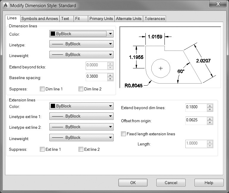
Lines Settings
The Lines tab (see Figure 13-39) controls the dimension and extension lines within a dimension object. Figure 13-40 shows how these various settings map to dimension objects. The Dimension lines area allows you to set the color, linetype, and lineweight of the dimension lines as well as the spacing between dimension lines when creating baseline dimensions. The Extend beyond ticks: setting is available only when certain types of arrowheads are specified. For example, when an architectural tick is used, the Extend beyond ticks: setting controls how far past the tick to extend the dimension line. You can suppress the dimension line on either side of the text. This comes in handy when dimensioning in tight areas where the dimension lines tend to obscure dimension text.
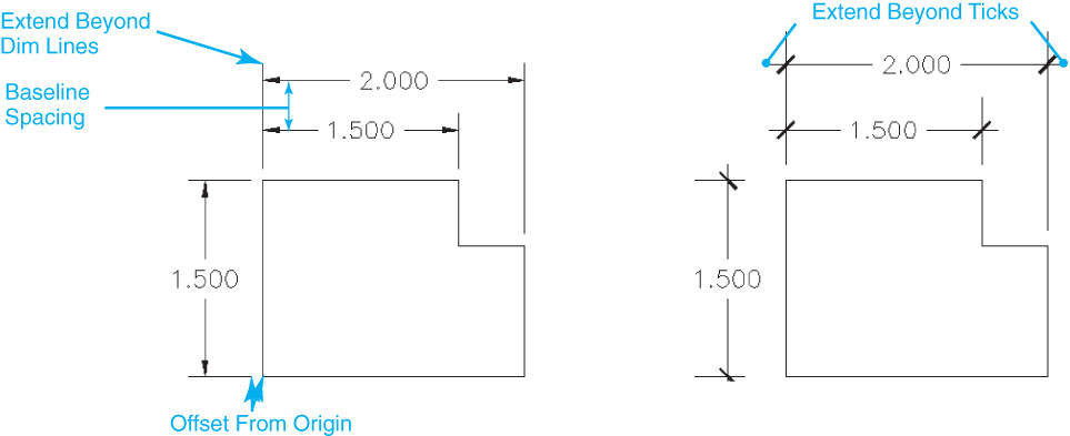
The Extension lines area has similar controls for extension lines. You can set the color, linetype, and lineweight of the extension lines as well as control the length of the extension line and the gap between the extension line and the object you are dimensioning.
Checking the Fixed length extension lines check box will create extension lines that are all the same length specified in the Length: box regardless of their origin point locations. The fixed length is calculated using the distance from the second extension line origin point (second pick point) to the dimension line location point (third pick point) minus the distance specified in the Offset from origin: box.
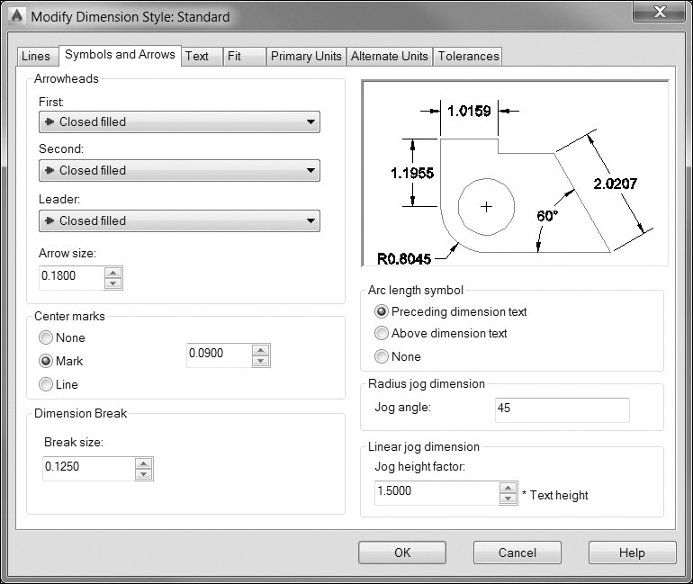
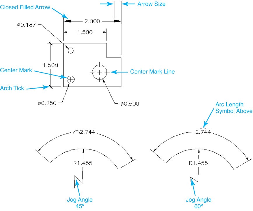
Symbols and Arrows
The Symbols and Arrows tab (see Figure 13-41) allows you to set the size and type of arrowheads used in dimensions. You can set different arrowheads for the first and second dimension lines as well as a separate arrowhead for leaders. The Center marks area allows you to set the size and type of center marks. This affects how center marks are shown in radial and diameter dimensions and also controls how center mark lines are created with the DIMCENTER command. The Arc length symbol area controls where the arc length symbol is displayed with the DIMARC command, and the Jog angle: setting controls the angle of the jogged segment in the DIMJOGGED command. Figure 13-42 shows examples of settings in the Symbols and Arrows tab.
Note
The Leader: arrowhead setting is used only by the old-style QLEADER command. Use the Multileader Style Manager introduced to control the arrowhead for the default leader type.
The Jog height factor: setting controls the height of the jog created by the Jog Line tool explained earlier.
Text Settings
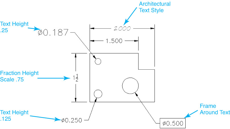
The Text tab (see Figure 13-43) controls how text is placed and how it looks. The Text appearance area allows you to set the text style used. The ... button displays the Style dialog box to allow you to create and modify text styles. The Text color: and Fill color: buttons control the color of the text and the color of the text background. You can also draw a box around the text by turning on the Draw frame around text option.
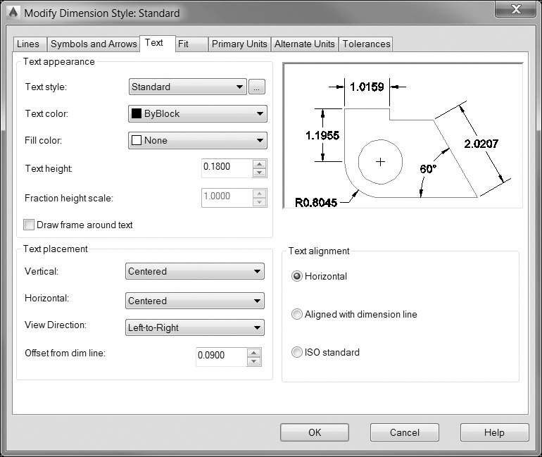
The Text height and Fraction height scale: settings control text height. The Fraction height scale is a scale factor applied to numerator and denominator text in a fraction. For example, if the Text height is set to .125 and the Fraction height scale is set to .5, the size of the numerator and denominator would be .0625, making the overall height of the fraction .125. Figure 13-44 shows examples of the Text appearance settings.
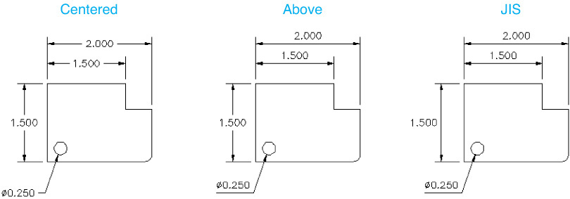
The Text placement area controls how text is placed in regard to the dimension lines and extension lines. The Offset from dim line: setting controls the gap between the dimension line and the dimension text. The Vertical: setting allows you to place the text above, below, or centered on the dimension line. You can also choose JIS, which places the dimension text to conform to the Japanese Industrial Standard. Figure 13-45 shows the effects of the Vertical: setting.
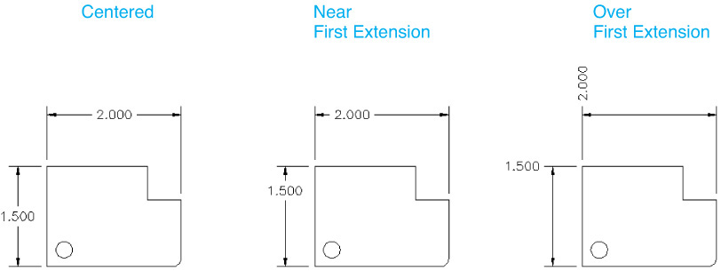
The Horizontal: setting controls where the text is placed in reference to the extension lines. You can place the text near the first or second extension line, or have the text drawn over the first or second extension line. Figure 13-46 shows the effects of the Horizontal: setting.
The View Direction: setting controls whether text reads from left-to-right or from right-to-left.
The Text alignment area controls whether text is always displayed horizontally or aligned with the dimension line. The ISO standard setting allows you to align text with one dimension line when text is inside the extension lines, but align it horizontally when it is outside the extension lines.
Fit and Scale Settings
The Fit tab (see Figure 13-47) controls the behavior and scale of dimension objects. The Fit options control how dimensions behave when AutoCAD cannot place both the dimension lines and text between the extension lines. Figure 13-48 shows examples of each of these settings.
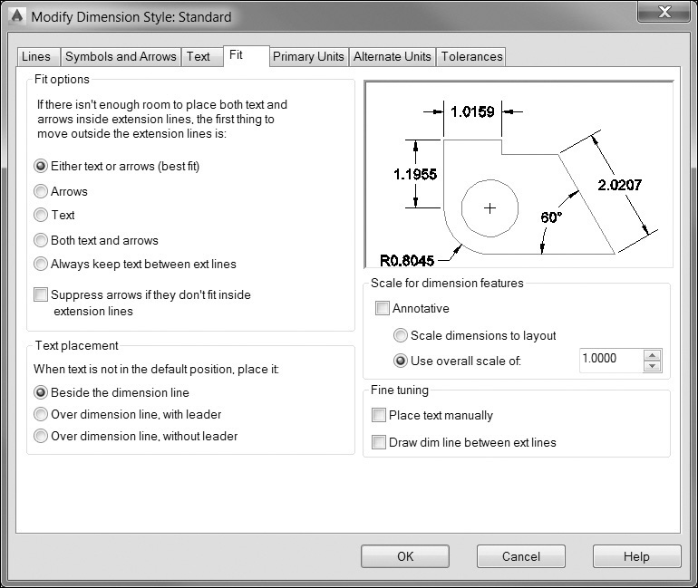
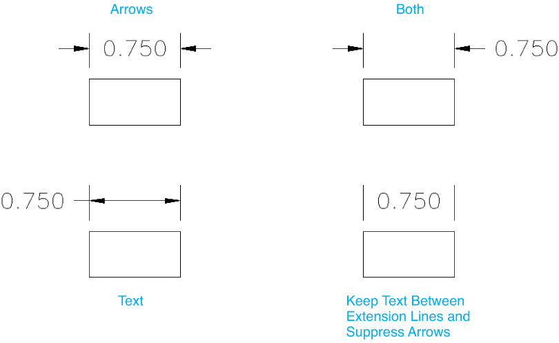
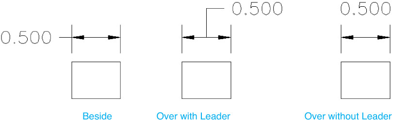
The Text placement area controls where text is placed when it is not in its default position. You can choose to have AutoCAD move the text beside the dimension line (outside the extension line), over the dimension line with a leader line running between the text and the dimension line, or over the dimension line without a leader. Figure 13-49 shows the effect of each of these options.
Chapter 1 discussed annotation scale factors. For example, if you have a drawing plotted at a scale of 1/8″ = 1-0″, you need to scale all your model space annotation by a factor of 96. This ensures that as the drawing is scaled down for plotting, the annotation objects appear at the correct size because they have been scaled up. The Scale for dimension features area controls the overall annotation scale of dimension objects.
The Annotative scale setting utilizes the AutoCAD Annotation Scale feature located on the right side of the status bar so that dimension features are scaled automatically when dimensions are added to your drawing and you have calculated a scale factor.
Note
It’s important to note that the Scale for dimension features settings affect only the size of dimension objects, not the values of the dimensions themselves.
For More Details
See page 8 in Chapter 1 for a detailed description of the Annotation Scale feature.
The Scale dimensions to layout setting will automatically scale all your dimension features to match the scale of the layout viewport. This feature requires that you add dimensions through the paper space viewport so that AutoCAD knows what scale you are currently working in.
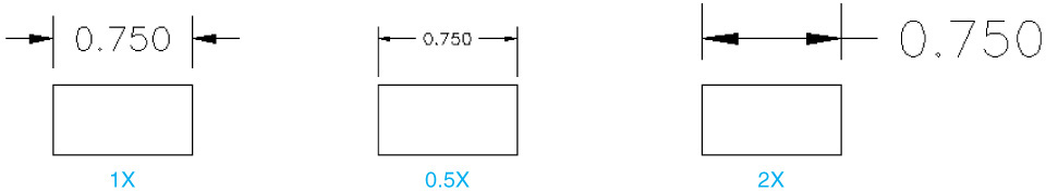
The Use overall scale of: setting is a manual scale factor that is applied to all dimension features. For example, if your text and arrowheads are set to a height of .125 and the overall scale is set to 2, AutoCAD will draw your text and arrowheads at a size of .25. Figure 13-50 shows an example of setting the overall dimension scale factor.
For More Details
See Chapter 14 for a detailed description of using paper space layouts and the different scale options for annotation features.
The Fine tuning area gives you some additional options for controlling the look of your dimension. When turned on, the Place text manually box adds an additional prompt when creating dimensions, which allows you to specify a location for the dimension text after you locate the dimension line.
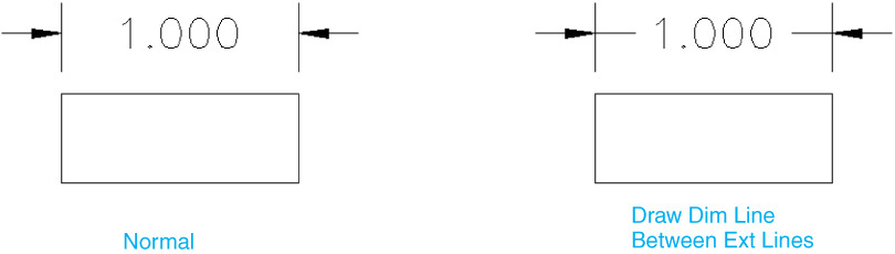
The Draw dim line between ext lines option will force a dimension line to be placed between the extension lines, regardless of the location of the dimension text. Figure 13-51 shows some examples of turning on this option.
Primary Units Tab
The Primary Units tab (see Figure 13-52) controls the formatting of the dimension text. The Linear dimensions area allows you to control how units are displayed; the Angular dimensions area controls the display of angular dimensions. The options are listed next.
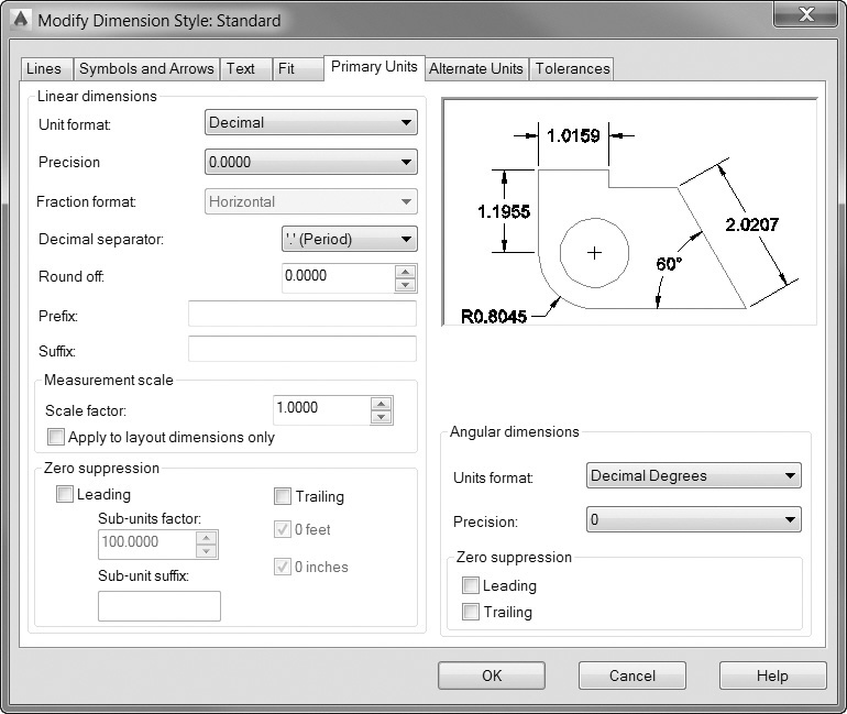
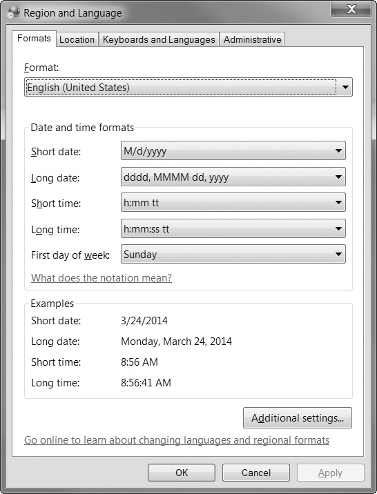
Unit Format
This option sets the units format for all dimension types except angular. This is typically set to match the units of your drawing. In addition to the standard AutoCAD unit settings, you can also choose the Windows Desktop units, which use the settings contained in the Region and Language options in the Windows Control Panel (see Figure 13-53).
In the Angular dimensions area, the Units format list allows you to control how angular dimensions are displayed. You can choose from Decimal Degrees, Degrees Minutes Seconds, Gradians, or Radian units.
Note
Although it is common to set the dimension units of a dimension style the same as the display units used in the drawing, it is not required. As an example, you might have Decimal display units set in the drawing and Architectural units set in a dimension style. The separate unit settings also make it possible to create additional dimension styles with distinct dimension unit settings so that you can use different dimension standards in the same drawing.
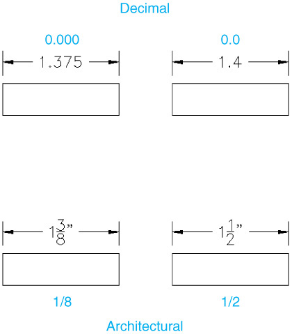
This option controls the number of decimal places in the dimension text. This setting controls only how the dimension text is displayed; it does not change the drawing geometry or affect the actual measured value of the dimension. There are two settings: one for linear dimensions and one for angular dimensions. Figure 13-54 shows some examples of this setting.
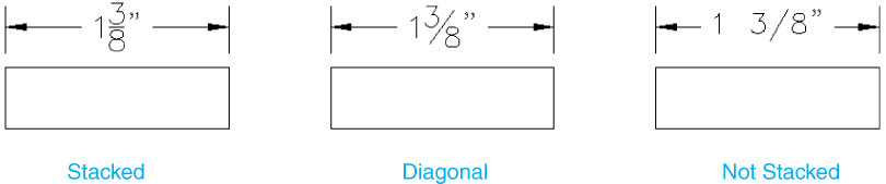
Fraction Format
This controls how fractions are displayed. This option is available only when the Unit format is set to either Architectural or Fractional. This format is used in conjunction with the Fraction height scale in the Text tab. Figure 13-55 shows examples of these settings.
Decimal Separator
When the Unit format is set to Decimal, this option sets the character used for the decimal separator.
Round Off
This option sets the rounding rules for all dimension types except angular. If you enter a value of 0.25, all distances are rounded to the nearest 0.25 unit. If you enter a value of 1.0, all dimension distances are rounded to the nearest integer. The number of digits displayed after the decimal point depends on the Precision setting. Like the Precision setting, this setting affects only how dimensions are displayed; it does not change the geometry or the actual measured value of the dimension.
The Prefix option allows you to set a prefix in the dimension text. The specified text is placed in front of the default dimension text. You can enter any text you want or use control codes to display special symbols. For example, entering the control code %%c displays the diameter symbol.
Suffix
The Suffix option works the same as the Prefix option except the specified text is placed after the default dimension text. For example, specifying the inch character (″) would place a ″ mark after each dimension.
Measurement Scale
The Measurement scale area allows you to define a scale factor for the default dimension text values. The Scale factor option sets a scale factor for linear dimension measurements. The value of any linear dimension is multiplied by this scale factor, and the resulting value is used as the default dimension text. For example, if you set a measurement scale factor of 2, the dimension text for a 1-inch line is displayed as 2 inches. The value does not apply to angular dimensions and is not applied to rounding values or to plus or minus tolerance values.
When the Apply to layout dimensions only option is turned on, AutoCAD will apply the measurement scale value only to dimensions created in layout (paper space) viewports.
Note
• When you enter a prefix, it replaces any default prefixes such as those used in diameter and radius dimensioning. If you specify tolerance values, the prefix is added to the tolerance text as well as to the regular dimension text.
• Do not confuse the Measurement scale with the Use overall scale of setting located on the Fit tab discussed earlier. The Measurement scale factor changes the numerical value of a dimension so that it no longer represents the actual length in the drawing. The Use overall scale of setting, or dimension scale, affects only the appearance of dimension features such as arrowheads and text size. The numerical dimension value always reflects its true length.
Zero Suppression
These options control the display of leading and trailing zeros in dimension text. For example, when set to decimal units, turning on the Leading option means that a dimension value of 0.5000 would be shown as .5000. With the Trailing option turned on, a dimension of 12.5000 would be displayed as 12.5. There are separate settings for both linear dimensions and angular dimensions.
The 0 feet and 0 inches options control the display of zeros in feet and inches dimensions. For example, when the 0 feet option is turned on, 0′-8″ would be displayed as 8″. With 0 inches turned on, 12′-0″ would be displayed as 12′.
The Sub-units factor and Sub-unit suffix settings allow you to specify a subunits factor and suffix so that when a dimension value is less than 1, you can switch to smaller units instead of displaying a leading zero.
Alternate Units Tab
The Alternate Units tab (see Figure 13-56) allows you to show dimensions in two different formats. A typical example of this is to show both inch and millimeter dimensions such as 2.00 [50.8 mm]. The Alternate Units tab contains settings that are similar to the Primary Units tab. To enable alternate units, select the Display alternate units box. Once this is selected, the remaining options are enabled.
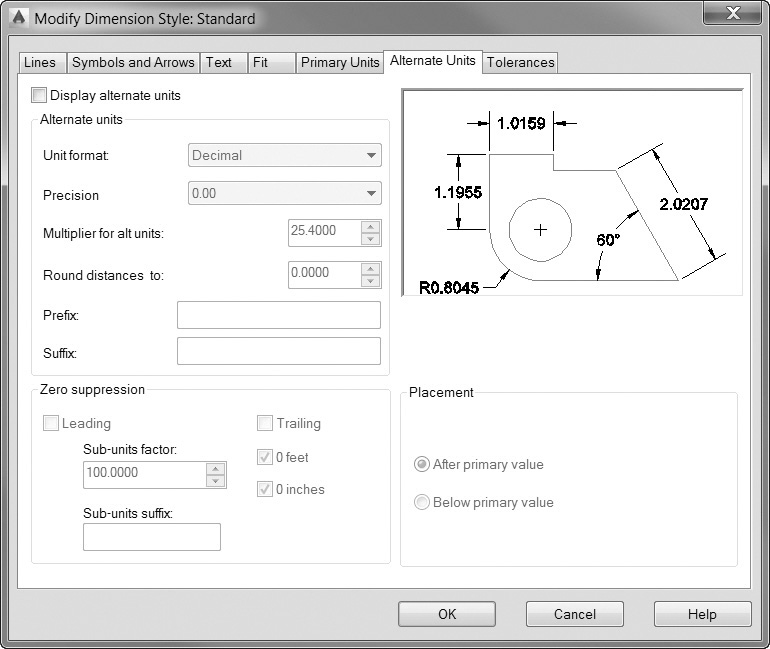
The Unit format and Precision options work the same as the Primary Units tab settings. When using fractional unit formats (Architectural and Fractional), you can choose between stacked or unstacked fractions.
Multiplier for Alternate Units and Round Distances To
The Multiplier for alt units: setting specifies the conversion factor between the primary units and the alternate units. For example, to convert inches to millimeters, specify a multiplier of 25.4. The value has no effect on angular dimensions. The Round distances to: setting allows you to apply a rounding value to the alternate dimensions. This rounding value is independent of the primary units round-off value.
Prefix and Suffix and Zero Suppression
The Prefix and Suffix values work the same as for the primary units. To place an mm notation after the alternate dimensions, set the suffix to mm. The Zero suppression settings also work the same as the Primary Units tab settings.
Placement
This controls where the alternate units are displayed. You can choose between After primary value and Below primary value.
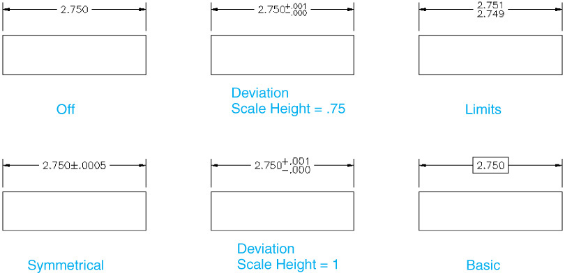
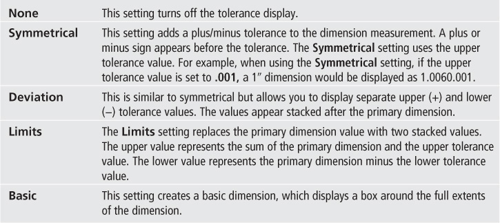
The Tolerances Tab
The Tolerances tab allows you to control the display and values of tolerances for both primary and alternate units. The Zero suppression and Precision settings work the same way as the primary and alternate units settings but control only the tolerance values. The Upper and Lower values control the upper and lower limits of the tolerance settings.
Method
The Method setting controls how the tolerances are displayed. These settings are described next. Figure 13-57 shows an example of each setting.
Scaling for Height
The Scaling for height setting controls the relative size of the tolerance text. The value is a scale factor, which is multiplied by the primary unit text height. For example, if you set a Scaling for height value of .5, the tolerance text would be half the size of the primary units. This is primarily used with the Deviation and Limits methods.
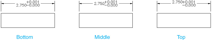
Vertical Position
This option controls the vertical location of the primary dimension text in relation to the tolerance text. You can choose either Top, Middle, or Bottom. Figure 13-58 shows examples of the Vertical position setting.
Exercise 13-10 Modifying an Existing Dimension Style
![]() Continue from Exercise 13-9. Start the DIMSTYLE command to display the Dimension Style Manager dialog box.
Continue from Exercise 13-9. Start the DIMSTYLE command to display the Dimension Style Manager dialog box.
![]() Choose the Mech dimension style, and choose the Modify... button. This will display the Modify Dimension Style dialog box.
Choose the Mech dimension style, and choose the Modify... button. This will display the Modify Dimension Style dialog box.
![]() In the Symbols and Arrows tab, set the Arrow size to .125.
In the Symbols and Arrows tab, set the Arrow size to .125.
![]() In the Text tab, choose the ... button next to the Text style list. This displays the Text Style dialog box. Choose New and create a text style named DIM using the ROMANS.SHX font. Choose Apply and then Close to close the Text Style dialog box. AutoCAD returns you to the Text tab of the Modify Dimension Style dialog box.
In the Text tab, choose the ... button next to the Text style list. This displays the Text Style dialog box. Choose New and create a text style named DIM using the ROMANS.SHX font. Choose Apply and then Close to close the Text Style dialog box. AutoCAD returns you to the Text tab of the Modify Dimension Style dialog box.
![]() Choose the Dim text style you just created in the Text style list, and set the Text height to .125.
Choose the Dim text style you just created in the Text style list, and set the Text height to .125.
![]() Choose OK to save the dimension style changes and return to the Dimension Style Manager dialog box. Select the Mech dimension style, and choose Set Current to set the dimension style current. Choose the Close button to end the DIMSTYLE command. Any dimensions that have this style are updated.
Choose OK to save the dimension style changes and return to the Dimension Style Manager dialog box. Select the Mech dimension style, and choose Set Current to set the dimension style current. Choose the Close button to end the DIMSTYLE command. Any dimensions that have this style are updated.
![]() Select the dimensions created in Exercises 13-8 and 13-9, and change their dimension styles to Mech by selecting the Mech style from the Dimension Style drop-down list on the expanded Annotation panel on the Home tab of the ribbon.
Select the dimensions created in Exercises 13-8 and 13-9, and change their dimension styles to Mech by selecting the Mech style from the Dimension Style drop-down list on the expanded Annotation panel on the Home tab of the ribbon.
![]() Save your drawing. Your drawing should resemble Figure 13-59.
Save your drawing. Your drawing should resemble Figure 13-59.
Modifying Dimension Styles Versus Overriding Dimension Styles
When modifying dimensions, any changes made to the dimension style will affect all the dimensions that use that style. There may be times when you want to change the settings for a single dimension without making changes to the dimension style. In this case, a dimension override is what you need.
A dimension override allows you to make changes to dimension settings without applying them to the dimension style. Once you make a dimension override, any new dimensions will be placed with the settings of the dimension override until that override is changed or deleted. The dimension objects created with the override will retain the override setting until the dimension style is reapplied to the dimension.
Note
A dimension override is similar to hard-coding object properties. For example, Chapter 6 showed how an object can have color, linetype, lineweight, and transparency settings that are different from the layer setting.
Overriding a Dimension Style
To create a dimension override, choose the Override... button from the Dimension Style Manager dialog box. When you choose this button, AutoCAD displays the Override Current Style dialog box (see Figure 13-60). This dialog box is the same as the Modify Dimension Style dialog box and allows you to make changes to the current dimension style settings. The difference is that the changes are not applied to the dimension style, but are stored in a <style overrides> setting that appears as a child style of the parent dimension (see Figure 13-61).
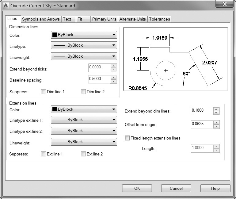
Once you create an override, the override settings are set current and are applied to all new dimensions.
Dimension Variables
Another way to create a dimension override is to change the dimension variables directly. The dimension variables are system variables that control the dimension settings. When you make changes to the dimension style, its corresponding dimension variable is also set accordingly. A dimension style is basically a collection of these dimension variable settings. AutoCAD’s dimension variables are listed in Appendix D. To change a dimension variable, just type the variable name and set the value. When you change a dimension variable, AutoCAD creates a dimension style override.
Saving an Override to a Style
If you decide you want to keep the override setting, you can save the setting to the current dimension style, making the changes permanent. To make the dimension overrides permanent, right-click on the <style overrides> in the Dimension Style Manager dialog box in the DIMSTYLE command, and choose Save to current style in the menu. Doing this will apply the dimension override settings to all the dimensions that use the current style.
Note
When you save a style override to a new dimension style, any dimensions created with the style overrides keep their original dimension style and the override settings. They are not changed to the new dimension style.
You can also save the dimension override settings to a new dimension style. To do this, right-click on the <style overrides> in the Dimension Style Manager dialog box in the DIMSTYLE command, and choose Rename. You can then type in a name for the new dimension style. When you press <Enter>, AutoCAD will save the dimension style overrides to a new dimension style and move that style to the top level in the style list.
Deleting an Override
There are two ways to delete a style override. One way is to set another dimension style current. AutoCAD will display an Alert box stating that the overrides will be deleted (see Figure 13-62). Choose Yes to delete the current style override.
Note
When you delete a style override, any dimensions created with the style overrides keep their override settings.
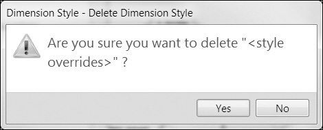
Another way to delete an override is to select the override name in the Dimension Style Manager dialog box and press the <Del> key on your keyboard. You can also right-click on the override name and choose Delete from the menu. AutoCAD will ask whether you’re sure you want to delete the override. Choose Yes to delete the override.
Exercise 13-11 Overriding a Dimension Style
![]() Continue from Exercise 13-10.
Continue from Exercise 13-10.
![]() Start the DIMSTYLE command. AutoCAD displays the Dimension Style Manager dialog box. Select the Mech dimension style and choose the Override... button. AutoCAD displays the Override Current Style dialog box.
Start the DIMSTYLE command. AutoCAD displays the Dimension Style Manager dialog box. Select the Mech dimension style and choose the Override... button. AutoCAD displays the Override Current Style dialog box.
![]() In the Tolerances tab, set the Method to Deviation. Set the Upper Value to .005 and the Lower Value to 0. Set the Scaling for height to .5 and turn on the Leading zero suppression. Choose OK to finish creating the overrides. AutoCAD returns you to the Dimension Style Manager dialog box. You should see the override listed as a child style of the Mech dimension style (see Figure 13-63). Choose Close to end the DIMSTYLE command.
In the Tolerances tab, set the Method to Deviation. Set the Upper Value to .005 and the Lower Value to 0. Set the Scaling for height to .5 and turn on the Leading zero suppression. Choose OK to finish creating the overrides. AutoCAD returns you to the Dimension Style Manager dialog box. You should see the override listed as a child style of the Mech dimension style (see Figure 13-63). Choose Close to end the DIMSTYLE command.
![]() Start the DIMDIAMETER command, and select the circle shown at P1 in Figure 13-64. Place the dimension as shown. The new dimension has the settings of the override while the existing dimensions remain unchanged.
Start the DIMDIAMETER command, and select the circle shown at P1 in Figure 13-64. Place the dimension as shown. The new dimension has the settings of the override while the existing dimensions remain unchanged.
![]() Save your drawing. Your drawing should look like Figure 13-64.
Save your drawing. Your drawing should look like Figure 13-64.
Comparing Dimension Styles
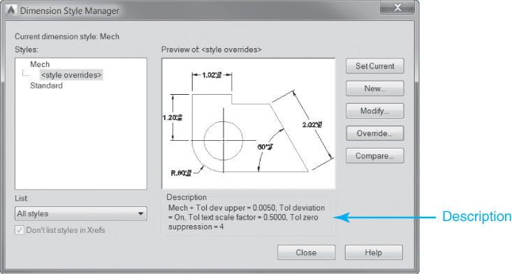
If you have a dimension style override or more than one dimension style, it is often helpful to know the differences between these styles. AutoCAD can compare two dimension styles and tell you which settings are different. When you select a dimension style in the Dimension Style Manager dialog box, AutoCAD will give you a description of the dimension style. If that style was based on an existing dimension style, AutoCAD will list the changes in the Description area (see Figure 13-65).
Another way to compare dimensions is to choose the Compare... button in the Dimension Style Manager dialog box. When you choose this button, AutoCAD will display the Compare Dimension Styles dialog box (see Figure 13-66).
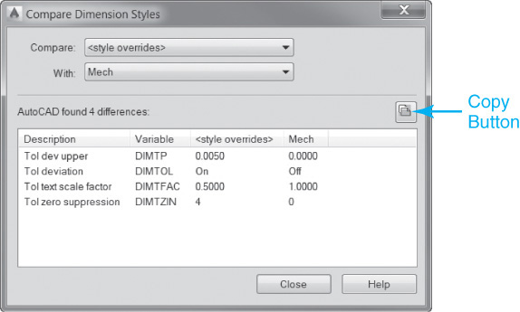
To compare two dimension styles, select one dimension style in the Compare: list and one style in the With: list. AutoCAD will display the differences in the bottom portion of the dialog box. To see a listing of all the settings for a given dimension style, select the style in the Compare: list and choose <none> in the With: list. AutoCAD will list all the dimension settings for that style. You can copy the list of results to the Windows Clipboard by choosing the Copy button (see Figure 13-66). The list is copied as tab-separated text, which can then be pasted into another Windows application.
Creating Leaders
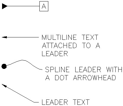
Leaders are used for a variety of items when annotating a drawing, such as manufacturing notes, detail bubbles, etc. In general, a leader consists of an end symbol (arrowhead, dot, circle, etc.), a leader line (either curved or straight), and a callout (mtext, block, tolerance, etc.). Figure 13-67 shows some different examples of leaders. Leaders are created with the MLEADER command.
The Multileader Tool
By default, when you start the MLEADER command, AutoCAD prompts you to Specify leader arrowhead location or ![]() so that you first select the arrowhead location. AutoCAD then prompts you to Specify leader landing location or
so that you first select the arrowhead location. AutoCAD then prompts you to Specify leader landing location or ![]() . Picking a point creates the landing, or tail of the leader, and puts you in the multiline text editor so you can begin adding text.
. Picking a point creates the landing, or tail of the leader, and puts you in the multiline text editor so you can begin adding text.
Multileader |
|
Ribbon & Panel: |
Home | Annotation
|
Menu: |
Dimension | Multileader |
Command Line: |
MLEADER |
Command Alias: |
MLA |

It is possible to create a leader by locating either the arrowhead, the landing, or text first. You can specify which option to use via the command options when you start the MLEADER command or via a right-click menu. The method you specify remains in effect for subsequent leaders.
Note
AutoCAD’s MLEADER command replaces the QLEADER command, which created AutoCAD quick leaders. It is still possible to create quick leaders by entering QLEADER or LE at the keyboard.
You can change the multileader properties by selecting Options when you start the MLEADER command:
• Leader type Allows you to switch between straight line segments and a spline
• Leader landing Turns the leader landing (tail) on or off
• Content type Allows you to specify whether to use text, a block, or nothing
• Maxpoints The maximum number of pick points used to create a leader. Default value is two points
• First angle Allows you to constrain the angle of the first line to a specific angle increment
• Second angle Allows you to constrain the angle of the second line to a specific angle increment
You must use the Exit option to exit the Options settings and begin drawing leaders.
For More Details
See the next section in this chapter for more on creating geometric dimension and tolerance callouts. See Chapter 16 for more on creating and using blocks.
After you create a leader, the easiest way to edit it is by using grips. Grips can be used to relocate the arrowhead location and resize a leader tail by selecting special arrow grips. Leaders are associative just like dimensions; that is, if you move the text, the leader line will follow.
Note
The MLEADEREDIT command can also be used to add and remove leader lines. The command alias is MLE.
The Leaders Panel
The Leaders panel shown in Figure 13-68 provides quick access to all the commands and options discussed so far plus some additional useful multileader tools.
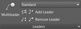
Using the Leaders panel, you can create new multileaders, add and remove leader lines, align multiple leaders, combine multiple block–type multileaders into a single multileader, and manage multileader styles.
The Add Leader Tool
You might be wondering about the word multi in the multileader name. The Add Leader tool allows you to add one or more leaders and arrowheads to an existing multileader object so that it points to multiple features. All the additional leader lines remain associated with the original leader so that if the text moves, so do the leader lines.
Add Leader |
|
Ribbon & Panel: |
Home | Annotation
|
Command Line: |
None |
Command Alias: |
None |

When you select the Add Leader tool, AutoCAD prompts you to Specify leader arrowhead location: so that you can select as many arrowhead locations as needed. You must press <Enter> to end the command.
Tip
It is also possible to add and remove multileaders by selecting the multileader and right-clicking to display the shortcut menu in Figure 13-69.
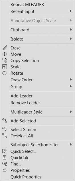
Remove Leader |
|
Ribbon & Panel: |
Home | Annotation |
|
|
Command Line: |
None |
Command Alias: |
None |

The Remove Leader Tool
The Remove Leader tool allows you to remove one or more leaders from an existing multileader.
Align |
|
Ribbon & Panel: |
Home | Annotation |
|
|
Menu: |
None |
Command Line: |
MLEADERALIGN |
Command Alias: |
MLA |

When you select the Remove Leader tool, AutoCAD prompts you to Select a multileader: so you can select the multileader to update. AutoCAD then prompts you to Specify leaders to remove: so that you can continue to remove leaders until you press <Enter> to end the command.
The Multileader Align Tool
The Multileader Align tool allows you to quickly align a group of leaders along a line that you specify as shown in Figure 13-70.
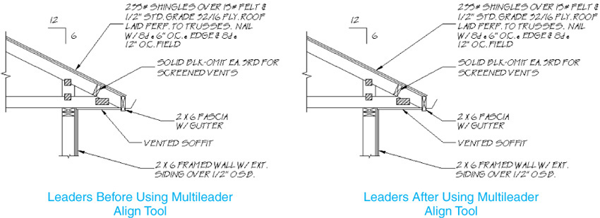
You can control the leader spacing by selecting Options when you start the Multileader Align tool:
• Distribute Distributes leaders evenly (default)
• Make leader segments Parallel Makes angle portion of leader lines parallel
Ribbon & Panel: |
Home | Annotation
|
Menu: |
None |
Command Line: |
MLEADERCOLLECT |
Command Alias: |
MLC |

• Specify Spacing Allows you to specify the spacing distance
• Use current spacing
The Multileader Collect Tool
The Multileader Collect tool allows you to collect and combine multiple blocks so that they are attached to one landing line as shown in Figure 13-71.
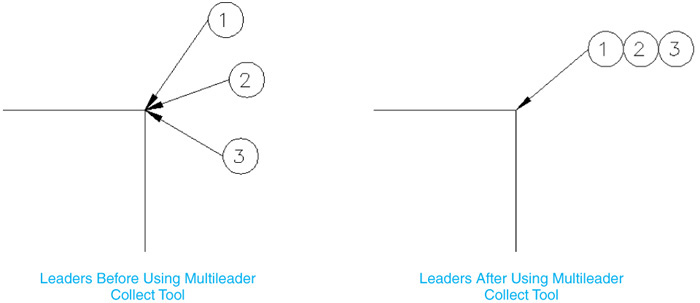
Using the Multileader Collect tool, blocks can be collected horizontally, vertically, or within a user-defined area.
Multileader Style |
|
Ribbon & Panel: |
Home | Annotation
|
Menu: |
None |
Command Line: |
MLEADERSTYLES |
Command Alias: |
MLS |
Multileader Style
The Multileader Style Manager shown in Figure 13-72 allows you to control the multileader format and display options using a multileader style in a similar fashion to text styles, table styles, and dimension styles.
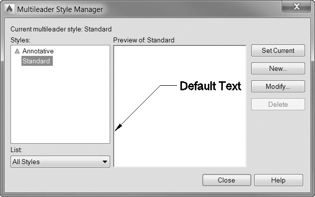
Selecting the New... or Modify... button displays the Modify Multileader Style dialog box shown in Figure 13-73.
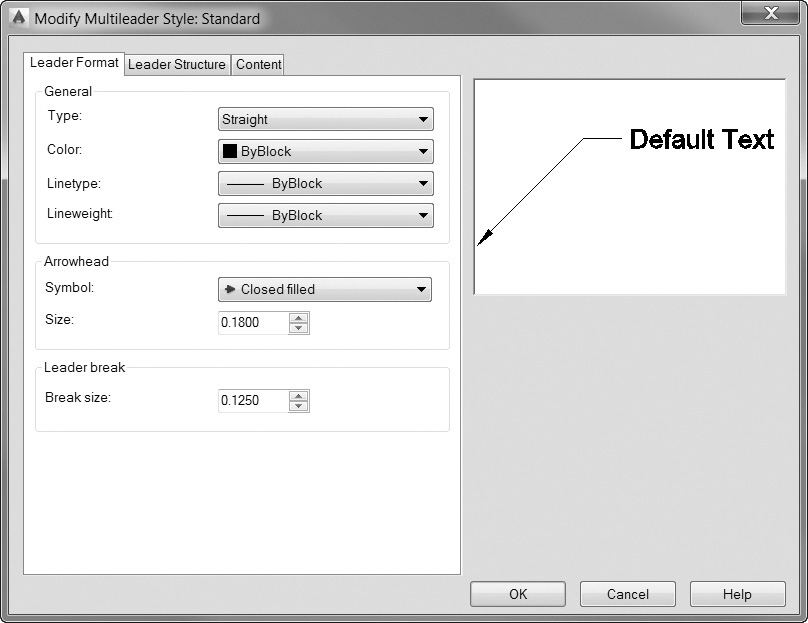
The Leader Format tab (Figure 13-73) allows you to specify the type of leader line to use (straight or spline), control general properties (color, linetype, and lineweight), as well as specify the arrowhead type and size. The Leader break setting determines the break size for the selected multileader when the DIMBREAK command is used.
The Leader Structure tab (see Figure 13-74) allows you to control constraints such as the maximum number of points and the first and second segment angles. You can also turn the landing (tail) on and off, as well as specify its length. The Scale area allows you to take advantage of Annotative scaling, use the layout viewport scale, or specify the scale explicitly so text and arrows are created the correct size.
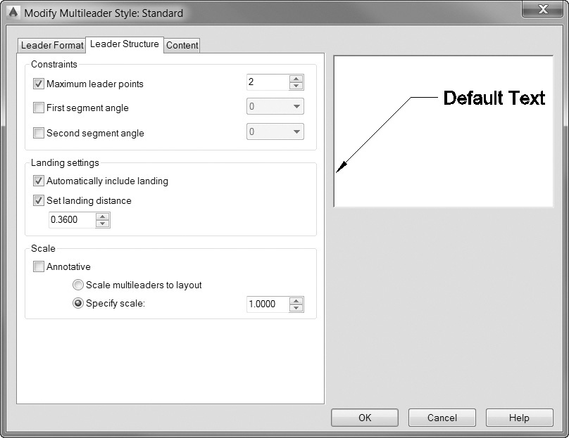
The Content tab (see Figure 13-75) allows you to indicate whether to use text, blocks, or nothing when creating leaders using the Multileader type: drop-down list. If you are using text, the Text options and Leader connection areas are enabled so that you can control default text, text style, angle, color, and height. The Leader connection area allows you to control where the text is attached and specify the gap distance between the end of the landing and the beginning of the text.
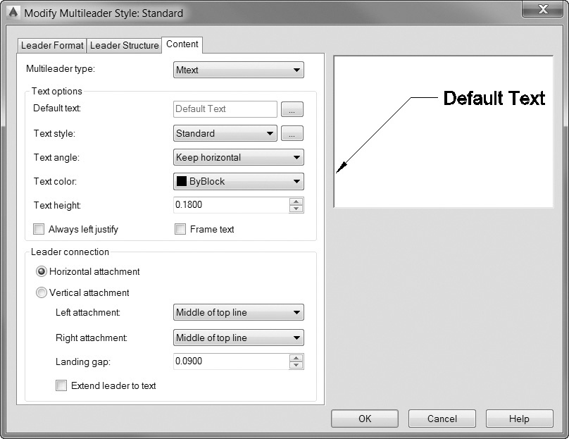
If you specify a block as the Multileader type, the Text options and Leader connection areas change to Block options so that you can specify a block name, where the block will be attached, its color, and scale.
When possible, you should try to use multileader styles to control the appearance of multiline leaders in your drawings.
Note
AutoCAD provides a number of predefined annotation blocks that allow you to quickly create detail callouts, circles, boxes, and other standard items that include attribute information. See Chapter 16 for more information about blocks and attributes.
Tip
The Properties palette also provides access to all the multileader settings discussed in this section for easy updating after a multileader is created.
Exercise 13-12 Creating a Leader
![]() Continue from Exercise 13-11.
Continue from Exercise 13-11.
![]() Display the Multileader Style Manager dialog box. Select the Modify... button, and on the Leader Format tab of the Modify Multileader Style dialog box, set the Arrowhead to Dot and the Size: to 0.125.
Display the Multileader Style Manager dialog box. Select the Modify... button, and on the Leader Format tab of the Modify Multileader Style dialog box, set the Arrowhead to Dot and the Size: to 0.125.
![]() On the Content tab, set the Text height: to 0.125 and the Text style: to Dim.
On the Content tab, set the Text height: to 0.125 and the Text style: to Dim.
![]() Choose OK to save the change, and close the Multiline Style Manager dialog box by selecting Close.
Choose OK to save the change, and close the Multiline Style Manager dialog box by selecting Close.
![]() Start the MLEADER command. AutoCAD prompts you to Specify leader arrowhead location or
Start the MLEADER command. AutoCAD prompts you to Specify leader arrowhead location or ![]() .
.
![]() Pick the points P1 and P2 shown in Figure 13-76 and press <Enter> to end the point placement. AutoCAD starts the multiline text editor.
Pick the points P1 and P2 shown in Figure 13-76 and press <Enter> to end the point placement. AutoCAD starts the multiline text editor.
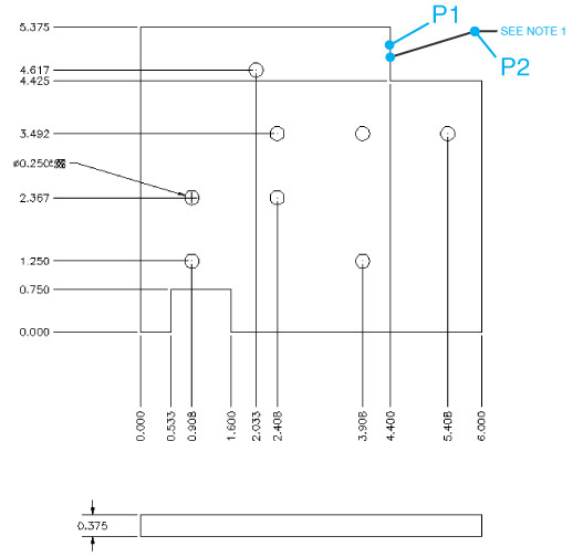
![]() Type SEE NOTE 1 and select Close Text Editor or click anywhere outside the multiline text editor to end the MLEADER command.
Type SEE NOTE 1 and select Close Text Editor or click anywhere outside the multiline text editor to end the MLEADER command.
![]() Save your drawing. Your drawing should look like Figure 13-76.
Save your drawing. Your drawing should look like Figure 13-76.
Creating Geometric Dimension and Tolerance Symbols (GD&T)
Geometric dimensioning and tolerancing (GD&T) is a method of specifying geometry requirements in mechanical engineering drawings. GD&T callouts use a series of symbols and numbers to convey specifications for mechanical parts and assemblies. Figure 13-77 shows an example of a GD&T callout (also called a feature control frame). GD&T is used primarily in mechanical design environments such as automotive, aerospace, electronic, and other manufacturing industries.
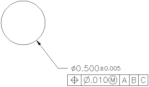
GD&T symbols denote acceptable variations in form, profile, orientation, location, and runout of a feature. You add GD&T callout symbols in feature control frames. These frames contain all the tolerance information for a single dimension. In AutoCAD, GD&T control feature frames are created with either the LEADER or TOLERANCE command. The LEADER command creates GD&T callouts with a leader attached to them, whereas the TOLERANCE command creates callouts without leaders.
Tolerance |
|
Ribbon & Panel: |
Annotate | Dimensions
|
Menu: |
Dimension | Tolerance |
Command Line: |
TOLERANCE |
Command Alias: |
TOL |

For More Details
Geometric tolerancing is covered by ASME Y14.5M—1994, which supersedes ANSI Y14.5M—1982. See Appendix A for more on drafting standards.
When you create a GD&T callout, AutoCAD displays the Geometric Tolerance dialog box (see Figure 13-78). With this dialog box, you can construct GD&T callouts. To construct a callout, work from left to right to specify the symbols and tolerance values that apply to the feature you are dimensioning. When you select the Sym box, AutoCAD displays the Symbol dialog box (see Figure 13-79).
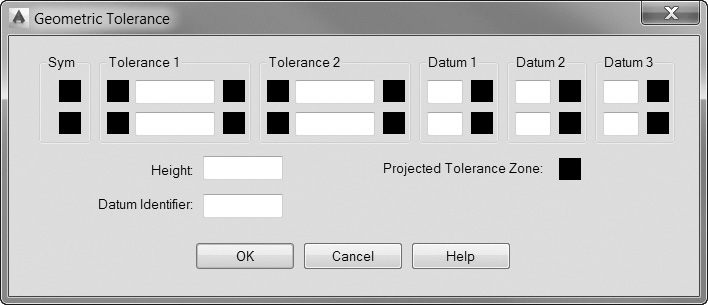
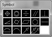
GDT Font
The GDT font used in the TOLERANCE command, as well as other mechanical callout symbols, can be found in the GDT.SHX font file. The GDT.SHX font uses geometric symbols for the lowercase letters a–z, and the capital Roman simplex letters for the uppercase letters A–Z. The symbols used in the GDT.SHX font are shown in Figure 13-80 along with their corresponding lowercase letter representation.
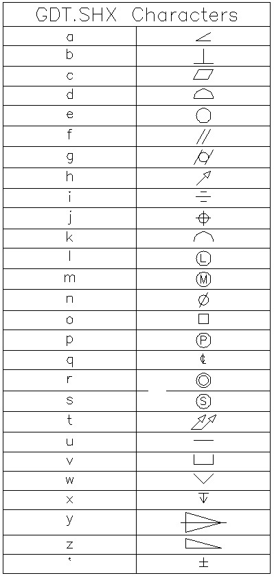
Inspection Dimensions
Inspection dimensions allow you to communicate how often manufactured parts should be checked to ensure that the tolerances of a part stay within the range specified in the dimension value. This is done using an inspection label, dimension value, and inspection rate as shown in Figure 13-81.
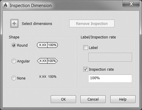
Inspect |
|
Ribbon & Panel: |
Annotate | Dimensions
|
Menu: |
Dimension | Inspection |
Command Line: |
DIMINSPECT |
Command Alias: |
None |

Note
You can add inspection dimensions to any type of dimension.
The dimension value is the value of the dimension before the inspection dimension is added. It can contain tolerances, text, and the measured value. The label and inspection rate fields are added using the Inspection tool explained below.
The DIMINSPECT command allows you to add or remove inspection dimensions and control their appearance including the shape, label, and inspection rate via the Inspection Dimension dialog box shown in Figure 13-81.
The Shape area allows you to control the type of inspection dimension shape used. You can switch between round, angular, and none.
The Label check box allows you to add a text label to the inspection dimensions. The label is located on the far left of the inspection dimension as shown in Figure 13-82.
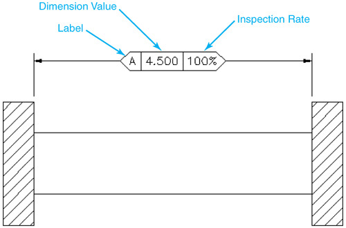
The Inspection rate check box allows you to indicate the frequency that the dimension should be inspected and is typically expressed as a percentage. The inspection rate is located on the far right of the inspection dimension as shown in Figure 13-82.
Tip
You can change the shape, label, and inspection rate of an inspection dimension after it is created using the Properties palette under the Miscellaneous category.
Modifying Dimensions
When you use associative dimensions and make changes to your geometry, the dimensions will change right along with it. However, you may need to modify dimension objects for a number of other reasons: to relocate the dimension text, to flip the arrowheads to the other side of the dimension line, or to modify the dimension text. In this section, you’ll look at some ways to make changes to dimension objects.
Dimensions are objects, just as lines, arcs, circles, and text are objects. As such, they can be moved, copied, rotated, and so on just like other objects. However, unlike other objects, dimensions contain multiple parts (text, dimension lines, extension lines, etc.), and each part can be modified. In the next sections, you’ll take a look at some different methods of modifying dimensions.
Grip Editing Dimensions
Grip editing is one of the easiest ways to modify dimensions. When you select a dimension object, AutoCAD will display grip edit points at the definition points, the ends of the dimension lines, and the insertion point of the dimension text. By selecting and moving these grips, you can quickly and easily modify dimension objects. Many grips are multifunctional so that if you hover your cursor over a grip, a shortcut menu similar to the one shown in Figure 13-83 is displayed. It provides access to many different dimension commands and options.
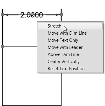
Note
Take care when you use grip editing on dimension definition points. If you have associate dimensioning turned on (DIMASSOC set to 2), modifying the definition points of a dimension will drop the association between the dimension and its object. When this happens, AutoCAD will display a message at the command line stating: Dimension extension disassociated. This occurs only when modifying the definition points; modifying the dimension line or text grips has no effect on associativity.
Note
If you select a grip so that it is active (red), you can use the <Ctrl> key to cycle through all of the commands and options on the Multifunctional Grip menu. The current command or option is displayed at the command line as you cycle through.
Tip
The Move Text Only option found on the dimension text Multifunctional Grip menu is the only way to break text free from a dimension so that you can move it alone without affecting the dimension line appearance and configuration.
Right-Click Shortcut Menu
AutoCAD’s right-click context menu also provides some editing abilities with dimensions. To activate the right-click menu, first select the dimension object(s) to activate its grips and then right-click anywhere on the drawing to display the menu. When dimensions are selected, the right-click menu will display the dimension-related menu options described in the following sections.
Dimension Style
This submenu allows you to apply a different dimension style to the selected dimensions. When you choose this option, you can select from a list of currently defined dimension styles. If you’ve made changes to the dimension and want to save those changes to a new style, choose the Save as New Style option. AutoCAD will display the Save as New Dimension Style dialog box, where you can type a new dimension style name or choose an existing dimension style name to overwrite.
Precision
This submenu allows you to modify the precision setting of the dimension text. The options for this menu change depending on the units set in the object’s dimension style.
Remove Style Overrides
This submenu removes any dimension style overrides applied to the dimension.
Annotative Object Scale
This submenu is enabled only if you are using the Annotation Scale feature for dimensions. When enabled, this option displays a submenu with options to add or remove annotation scales so the same dimension can be used for multiple-scale drawings. It is also possible to align multiple-scale representations so they are in the same location using the Synchronize Multiple-scale Positions option.
For More Details
See page 8 in Chapter 1 for a detailed description of the Annotation Scale feature.
Exercise 13-13 Relocating Dimension Text
![]() Open drawing EX13-13 in the student data files. This drawing has a number of overlapping dimensions.
Open drawing EX13-13 in the student data files. This drawing has a number of overlapping dimensions.
To access student data files, go to www.pearsondesigncentral.com.
![]() Select the dimension shown at P1 in Figure 13-84. Hover your cursor over the text grip to display the Multifunctional Grip menu, and select Move with Leader. AutoCAD will start dragging the dimension text. Place the dimension text as shown in Figure 13-85.
Select the dimension shown at P1 in Figure 13-84. Hover your cursor over the text grip to display the Multifunctional Grip menu, and select Move with Leader. AutoCAD will start dragging the dimension text. Place the dimension text as shown in Figure 13-85.
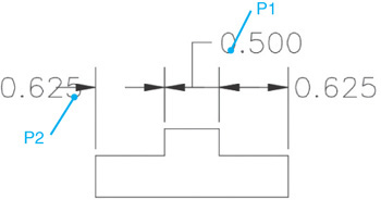
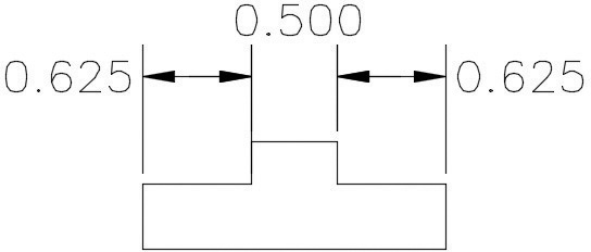
![]() Select the arrowhead shown at P2 in Figure 13-84. Hover your cursor over the arrowhead grip to display the Multifunctional Grip menu, and select Flip Arrow. The arrowhead flips to the other side of the extension line.
Select the arrowhead shown at P2 in Figure 13-84. Hover your cursor over the arrowhead grip to display the Multifunctional Grip menu, and select Flip Arrow. The arrowhead flips to the other side of the extension line.
![]() Save your drawing as CH13_EXERCISE13.
Save your drawing as CH13_EXERCISE13.
Modifying Dimension Text and Extension Lines
Sometimes it is necessary to modify dimension text and extension lines after a dimension has been created. The following sections provide an overview of some of the available tools and methods to replace, relocate, and modify dimension text, as well as change the angle of dimension extension lines in order to create oblique dimensions.
The DDEDIT Command
The DDEDIT command works on dimension objects as well as regular text and mtext objects. Simply select the dimension object when you are prompted to Select annotation object:. AutoCAD will display the dimension text in the multiline text editor. AutoCAD’s default dimension text will appear highlighted. You can place additional text before or after the default text, or replace it altogether.
Oblique |
|
Ribbon & Panel: |
Annotate | Dimensions
|
Menu: |
Dimension | Oblique |
Command Line: |
DIMEDIT |
Command Alias: |
DIMED |

If you delete the default dimension text, you can restore it by typing <> brackets in the mtext editor. AutoCAD will replace the <> brackets with the measured distance between the definition points.
Tip
If alternate dimensions are turned off, you can show the alternate dimension text by placing the square brackets [] along with the default brackets text <>. This works only if the default dimension text is present.
The Oblique Tool
The Oblique tool allows you to adjust the angle of the extension lines for linear dimensions using the Oblique option of the DIMEDIT command. The Oblique tool is useful when extension lines conflict with other features of the drawing or you need to dimension an isometric drawing.
Align Text |
|
Ribbon & Panel: |
Annotate | Dimensions |
Menu: |
Dimension | Align Text |
Command Line: |
DIMTEDIT |
Command Alias: |
DIMTED |
When you start the Oblique tool, AutoCAD prompts you to Select objects: so you can select one or more dimensions and press <Enter>. AutoCAD then prompts you to Enter obliquing angle (press Enter for none): so you can enter the desired oblique angle.
Align Text Tools
The Align Text tools allow you to relocate or rotate dimension text using any of the DIMTEDIT command options described in the following table.
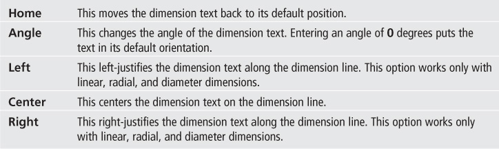
Exercise 13-14 Editing Dimension Text and Extension Lines
![]() Open drawing EX13-14 in the student data files.
Open drawing EX13-14 in the student data files.
To access student data files, go to www.pearsondesigncentral.com.
![]() Select the Oblique tool from the expanded Dimensions panel on the Annotate tab of the ribbon.
Select the Oblique tool from the expanded Dimensions panel on the Annotate tab of the ribbon.
![]() Select the dimensions shown at P1 and P2 in Figure 13-86, and press <Enter>. AutoCAD prompts you to Enter obliquing angle (press ENTER for none):.
Select the dimensions shown at P1 and P2 in Figure 13-86, and press <Enter>. AutoCAD prompts you to Enter obliquing angle (press ENTER for none):.
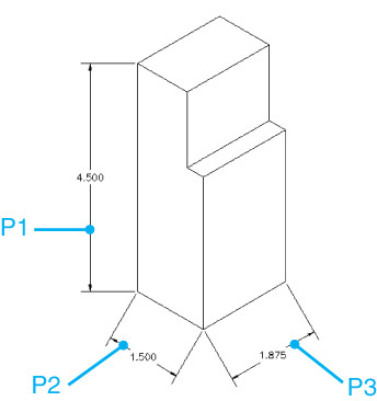
![]() Type 30, and press <Enter>. AutoCAD adjusts the angle of the extension lines.
Type 30, and press <Enter>. AutoCAD adjusts the angle of the extension lines.
![]() Select the Oblique tool again. Select the dimension shown at P3 in Figure 13-86, and press <Enter>.
Select the Oblique tool again. Select the dimension shown at P3 in Figure 13-86, and press <Enter>.
![]() Set the oblique angle to 150. AutoCAD adjusts the extension line angle.
Set the oblique angle to 150. AutoCAD adjusts the extension line angle.
![]() Select the Text Angle tool from the expanded Dimensions panel on the Annotate tab of the ribbon. AutoCAD prompts you to Select dimension:. Select the dimension text shown at P1 in Figure 13-86.
Select the Text Angle tool from the expanded Dimensions panel on the Annotate tab of the ribbon. AutoCAD prompts you to Select dimension:. Select the dimension text shown at P1 in Figure 13-86.
![]() AutoCAD prompts you to Specify angle for dimension text:. Enter –30 for the dimension text angle. AutoCAD rotates the dimension text.
AutoCAD prompts you to Specify angle for dimension text:. Enter –30 for the dimension text angle. AutoCAD rotates the dimension text.
![]() Restart the Text Angle tool, and select the dimension shown at P2 in Figure 13-86. Enter 30 for the dimension text angle. AutoCAD rotates the dimension text.
Restart the Text Angle tool, and select the dimension shown at P2 in Figure 13-86. Enter 30 for the dimension text angle. AutoCAD rotates the dimension text.
![]() Restart the Text Angle tool, and select the dimension shown at P3 in Figure 13-86. Enter –30 for the dimension text angle. AutoCAD rotates the dimension text.
Restart the Text Angle tool, and select the dimension shown at P3 in Figure 13-86. Enter –30 for the dimension text angle. AutoCAD rotates the dimension text.
![]() Start the DDEDIT command, and select the dimension text P1. AutoCAD displays the multiline text editor with the default dimension text shown. Highlight the dimension text, and set the oblique angle to 30. Choose OK to close the text editor.
Start the DDEDIT command, and select the dimension text P1. AutoCAD displays the multiline text editor with the default dimension text shown. Highlight the dimension text, and set the oblique angle to 30. Choose OK to close the text editor.
![]() Repeat step 11 with the text at points P2 and P3. Set the oblique angle to 30 and –30, respectively.
Repeat step 11 with the text at points P2 and P3. Set the oblique angle to 30 and –30, respectively.
![]() Save your drawing as CH13_EXERCISE14. Your drawing should resemble Figure 13-87.
Save your drawing as CH13_EXERCISE14. Your drawing should resemble Figure 13-87.
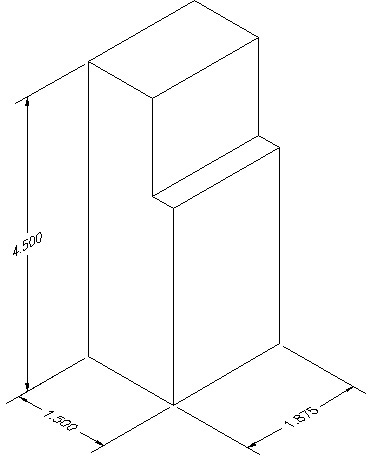
Reassociating Dimensions
The association between a dimension object and other drawing objects can be somewhat precarious. There are times when, in the course of editing object geometry, the original drawing objects may be redefined or modified in such a way that the objects’ association with a dimension object is lost. This may happen when polylines are exploded, when objects are trimmed or broken, or when multiple objects are joined. You may want to change the association to have the dimension be associated with another drawing object. AutoCAD provides a way to change dimension associativity with the DIMREASSOCIATE command.
Reassociate |
|
Ribbon & Panel: |
Annotate | Dimensions
|
Menu: |
Dimension | Reassociate Dimensions |
Command Line: |
DIMREASSOCIATE |
Command Alias: |
None |

When you start the DIMREASSOCIATE command, AutoCAD asks you to select a dimension object. When you select a dimension object, AutoCAD places an X at the first definition point and asks you to specify a new location for it. You can simply pick a new location for the definition point or skip to the next definition point by pressing <Enter>. Depending on the type of dimension, AutoCAD will continue to prompt you for a new location for each definition point until the dimension is completely defined.
Note
The DIMREASSOCIATE command works only with dimension objects. If a dimension is exploded or created when the DIMASSOC system variable is set to 0, the dimension text, lines, and arrows are no longer dimension objects and cannot be reassociated.
If you want to reassociate the dimension with a new object, use the Select object option and select a new object to associate with your dimension. The type of object you select will depend on the type of dimension you select.
Exercise 13-15 Reassociating a Dimension
![]() Continue from Exercise 13-14.
Continue from Exercise 13-14.
![]() Select the dimension shown at P1 in Figure 13-88. The grips for the dimension appear.
Select the dimension shown at P1 in Figure 13-88. The grips for the dimension appear.
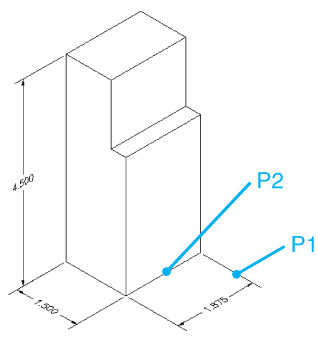
![]() Select the definition point grip shown at P1, and drag it off the object. AutoCAD displays the message Dimension extension disassociated at the command line. The dimension is no longer associated with the geometry.
Select the definition point grip shown at P1, and drag it off the object. AutoCAD displays the message Dimension extension disassociated at the command line. The dimension is no longer associated with the geometry.
![]() Start the DIMREASSOCIATE command. Select the dimension you just modified, and press <Enter>. AutoCAD places an X at the first defpoint and prompts you to Specify first extension line origin or
Start the DIMREASSOCIATE command. Select the dimension you just modified, and press <Enter>. AutoCAD places an X at the first defpoint and prompts you to Specify first extension line origin or ![]() .
.
![]() Choose the Select object option and select the line shown at P2 in Figure 13-88. AutoCAD reassociates the dimension with the selected line.
Choose the Select object option and select the line shown at P2 in Figure 13-88. AutoCAD reassociates the dimension with the selected line.
![]() Save your drawing.
Save your drawing.
Applying Dimension Styles
When working with multiple dimension styles, you may need to apply the settings on one style to an existing dimension. AutoCAD provides a number of ways to do this.
The Dimension Style Lists
One of the simplest ways to control the dimension styles in a drawing is via the Dimension Style list on the expanded Annotation panel on the Home tab of the ribbon (see Figure 13-89).
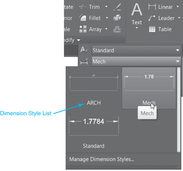
Selecting a dimension style from the Dimension Style drop-down list when no objects are selected will set the dimension style current so that any new dimensions will be created using that style. If one or more dimensions are selected so that their grips are displayed, selecting a different dimension style from the list will change the object’s associated dimension styles to the new dimension style.
You can also control dimension styles via the Dimension Style list on the Dimensions panel on the Annotate tab of the ribbon (see Figure 13-90).
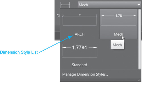
Properties Palette
A dimension style is simply an object property that applies only to dimension objects. Like other object properties, the Properties palette allows you to change the style of any selected dimension objects (see Figure 13-91). In addition to changing the style, you can also change the value of any style settings within the selected dimensions. This effectively creates dimension overrides for these dimension objects.
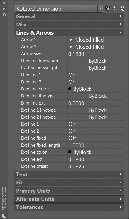
Match Properties
Because dimension styles are just a property of dimension objects, the MATCHPROP command can be used to match the dimension style properties of an existing dimension object. When you start the MATCHPROP command, you are prompted to select a source object and then the destination object(s). The properties of the source object are applied to the destination objects.
When you use the MATCHPROP command, by default, all valid properties of the source object are applied to the destination objects, including layer, color, linetype, transparency, etc. To control which properties are applied, choose the Settings option of the MATCHPROP command. This will display the Property Settings dialog box (see Figure 13-92). This allows you to select which properties you want to apply to the destination objects. To apply only the dimension style properties, place a check in the Dimension box and remove the checks from all other boxes. Selecting only the Dimension option will filter the properties so that only the dimension style properties of the source object are applied to the destination objects.
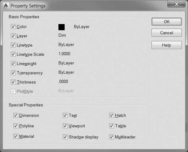
Tip
It is possible to use the MATCHPROP command between drawings so you can select the source object in a drawing other than the destination object(s). This is a handy way to copy dimension style settings from one drawing to another without re-creating it from scratch or using DesignCenter.
Exercise 13-16 Using Match Properties to Update Dimension Styles
![]() Open drawing EX13-16 in the student data files.
Open drawing EX13-16 in the student data files.
To access student data files, go to www.pearsondesigncentral.com.
![]() Start the MATCHPROP command. AutoCAD prompts you to Select source object:.
Start the MATCHPROP command. AutoCAD prompts you to Select source object:.
![]() Select the leader shown at P1 in Figure 13-93. This dimension has a dimension style override for the arrowhead. AutoCAD prompts you to Select destination object(s) or
Select the leader shown at P1 in Figure 13-93. This dimension has a dimension style override for the arrowhead. AutoCAD prompts you to Select destination object(s) or ![]() .
.
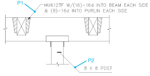
![]() Choose the Settings option. AutoCAD displays the Property Settings dialog box. In the Special Properties area, remove the check from all the settings except Dimension. Press OK to close the dialog box. AutoCAD prompts you to Select destination object(s) or
Choose the Settings option. AutoCAD displays the Property Settings dialog box. In the Special Properties area, remove the check from all the settings except Dimension. Press OK to close the dialog box. AutoCAD prompts you to Select destination object(s) or ![]() .
.
![]() Select the leader shown at P2 in Figure 13-93. AutoCAD updates the leader to match the source object and prompts you to Select destination object(s) or
Select the leader shown at P2 in Figure 13-93. AutoCAD updates the leader to match the source object and prompts you to Select destination object(s) or ![]() . Press <Enter> to end the MATCHPROP command.
. Press <Enter> to end the MATCHPROP command.
Update |
|
Ribbon & Panel: |
Annotate | Dimensions
|
Menu: |
Dimension | Update |
Command Line: |
-DIMSTYLE/ Apply |
Command Alias: |
None |

![]() Save your drawing as CH13_EXERCISE16.
Save your drawing as CH13_EXERCISE16.
The Dimension Update Tool
If you’ve created dimension style overrides and want to apply those overrides to an existing dimension, AutoCAD provides a tool for applying dimension styles (including overrides) to existing dimension objects.
When you choose this tool, AutoCAD lists the current dimension style, along with any overrides, at the command line and prompts you to Select objects:. Once you select the dimension object, AutoCAD applies the current dimension style settings, including overrides, to the selected dimensions.
Note
The Dimension Update tool is not technically a command. It is actually the Apply option of the -DIMSTYLE command, which is the command line version of the -DIMSTYLE command. When you select this tool, AutoCAD starts the -DIMSTYLE command and automatically selects the Apply option.
Chapter Summary
AutoCAD provides many different dimension types and settings to meet a wide array of industry standards. There are unidirectional dimensions for mechanical-type drawings and aligned dimensions for architectural standards. You can automatically insert a diameter or radial dimension with standard industry symbols by simply selecting circles or arcs. Linear dimensions can read either the actual length of objects or the distance between two points. Automatically stack dimensions using a specified spacing or chain strings of dimensions together using single pick points.
By default in AutoCAD, dimensions are associated with the geometry they are pointing to so that if the object changes, the dimensions update automatically to reflect the new size. Dimensions that are associated will even move with an object automatically when the object is moved in the drawing. Dimension associativity can be turned off, but it is not recommended because of all the benefits obtained by leaving it on.
Maintaining the appearance of dimensions on drawings so that they match industry standards is managed using dimension styles in AutoCAD. The Dimension Style Manager allows you to set and maintain the multitude of AutoCAD dimension settings. Dimension styles with different industry standards can be set up and stored in AutoCAD template (DWT) files so that they are instantly available when you start a new drawing. Occasionally, there is the need for an oddball dimension setting. Dimension overrides allow you to change a few dimension settings for a small number of dimensions without updating all of the dimensions in your drawing. Overrides can be set up in the Dimension Style Manager, or they can be applied directly to objects you select using the Properties palette. It is also possible to apply an override by using the Dimension Update tool to update any dimensions you select.
The Multileader tool allows you to quickly add feature notes with arrows to your drawings with a minimum of two pick points. The default is the arrowhead location and then location of the text, but it can be set to go the other direction. Multiple leader arrows can be added or removed with minimal effort. Multileader styles allow you to set up different leader types including splines and built-in part number bubbles, to name but a few.
As you have seen, controlling the appearance of dimensions and leader notes is a rather complex undertaking. There are literally hundreds of different dimension settings and controls to manage in order to get things to look just right. Fortunately, AutoCAD provides the ability to update and even match dimension styles to other existing dimensions in the current drawing or even between different drawings. This saves you the time-consuming process of going step-by-step through the Dimension Style Manager.
Chapter Test Questions
Multiple Choice
Circle the correct answer.
1. When using the DIMLINEAR command, which of the following is not a valid selection object?
a. Line
b. Arc
c. Ellipse
d. Circle
a. Is a linear dimension between the endpoints of an arc
b. Measures the true distance along an arc segment
c. Cannot be used on circles
d. None of the above
3. To create a dimension with angled (oblique) extension lines you would:
a. Use the DIMOBLIQUE command
b. Use the DIMEDIT command and select the Oblique option
c. Use grips to drag the extension lines to the desired angle
d. None of the above; you cannot create angled extension lines
4. A dimension style override:
a. Allows you to make temporary changes to a dimension style
b. Is applied to all dimensions with the current dimension style
c. Cannot be saved to a dimension style
d. None of the above
5. Setting the DIMASSOC system variable to 1:
a. Creates exploded dimensions
b. Creates dimensions that are not associated with other drawing objects
c. Creates dimensions that are associated with other drawing objects
d. You cannot set DIMASSOC to 1
6. In the Fit tab of the Modify Dimension Style dialog box, the Use overall scale of setting:
a. Controls the overall size of all elements of a dimension object
b. Controls the value of dimension text
c. Does not apply to dimensions placed in model space
d. All of the above
7. The Angle option of the DIMLINEAR command:
a. Creates an angular dimension instead of a linear dimension
b. Creates extension lines at the specified angle
c. Controls the angle of the dimension line
d. Controls the angle of the dimension text
8. To flip a dimension arrowhead:
a. Select the arrowhead and choose Flip Arrow from the Multifunctional Grip menu
b. Delete the dimension and re-create it picking different defpoints
c. Use the MIRROR command
d. You cannot flip dimension arrowheads once they are placed
9. A baseline dimension:
a. Creates dimensions that are aligned end to end
b. Creates dimensions that are referenced from a common extension line
c. Must be placed first before any other linear dimensions are created
d. None of the above
a. Automatically have the Ø symbol placed in front of the dimension text
b. Can be used with either arcs or circles
c. Cannot be used on an ellipse
d. All of the above
Matching
Write the number of the correct answer on the line.
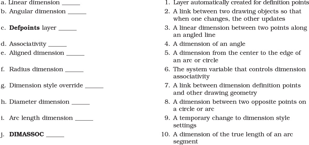
True or False
Circle the correct answer.
1. True or False: The Defpoints layer will never plot.
2. True or False: Dimensions cannot be exploded.
3. True or False: Dimension arrowheads can be flipped around the extension line.
4. True or False: The color and linetype of dimension lines are always BYLAYER.
5. True or False: You can override the default dimension text.
6. True or False: Centerline marks are created only with radius and diameter dimensions.
7. True or False: The QDIM command creates only linear dimensions.
8. True or False: Dimension style overrides are automatically applied to all existing dimension objects.
9. True or False: The DDEDIT command can be used to modify dimension objects.
10. True or False: The DIMRADIUS command can be used to dimension an ellipse.
Chapter Projects
![]() Project 13-1: Classroom Plan, continued from Chapter 8 [BASIC]
Project 13-1: Classroom Plan, continued from Chapter 8 [BASIC]
1. Open drawing P8-1 from Chapter 8.
2. Create a text style named ARCH and assign it the TrueType font Stylus_BT.
3. Create a dimension style called ARCH. Use the settings shown in Figures 13-100 through 13-104.
4. Set the Annotation Scale to 1/2″ = 1′-0″ on the status bar.
5. Add the dimensions shown in Figure 13-94.
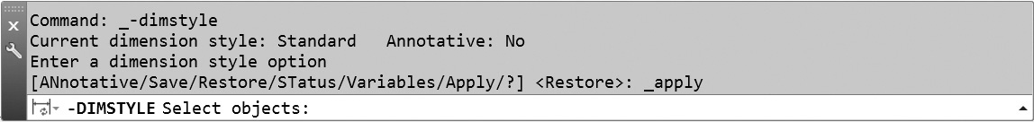
6. Save your drawing as P13-1.
![]() Project 13-2: B-Size Mechanical Border, continued from Chapter 11 [INTERMEDIATE]
Project 13-2: B-Size Mechanical Border, continued from Chapter 11 [INTERMEDIATE]
1. Open the template file Mechanical B-Size.DWT from Chapter 11.
2. Create a dimension style called Mech based on the Standard dimension style. Use the settings shown in Figures 13-95 through 13-99.
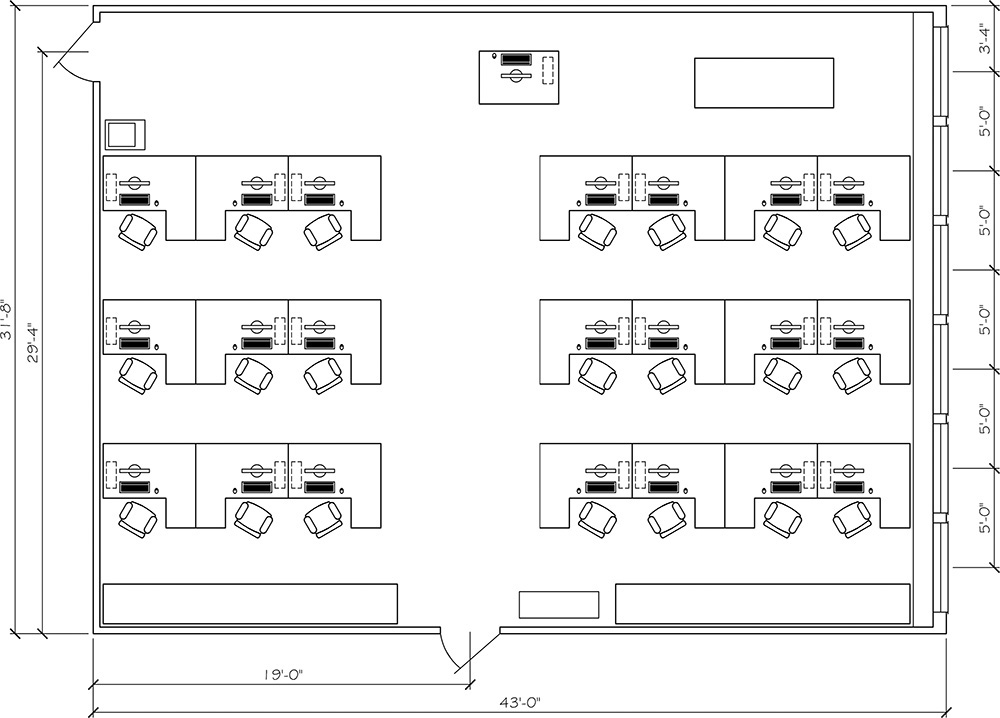
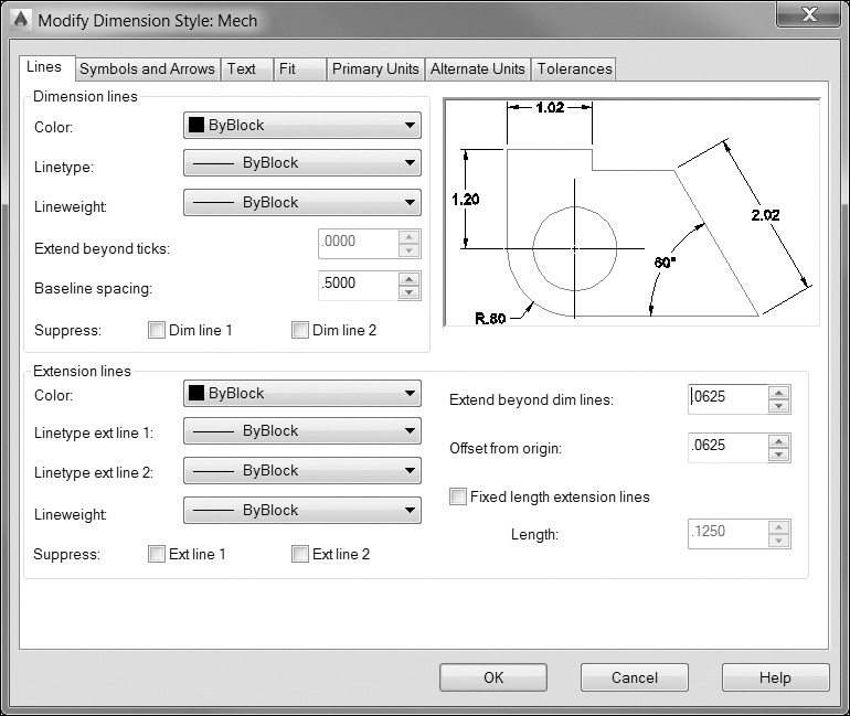
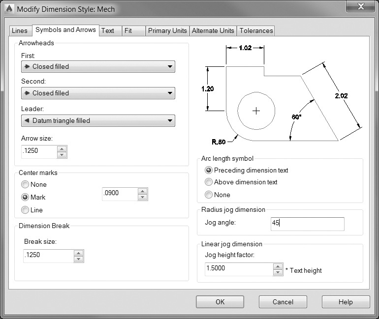
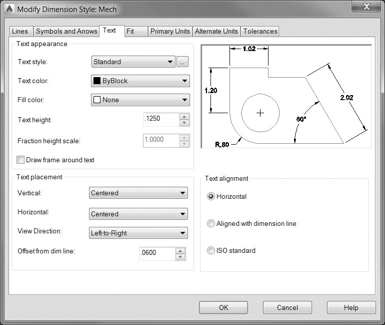
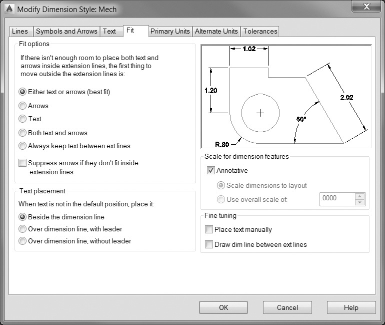
3. Save the drawing to a template file called Mechanical B-Size.DWT with the following description:
Mechanical Drawing Template:
B-Size - 17.0 × 11.0
Decimal Units - 0.000
Decimal Angles - 0.0
Dimension Style – Mech
![]() Project 13-3: Architectural D-Size Border, continued from Chapter 11 [ADVANCED]
Project 13-3: Architectural D-Size Border, continued from Chapter 11 [ADVANCED]
1. Open the template file Architectural D-Size.DWT from Chapter 11.
2. Create a text style named ARCH and assign it the TrueType font Stylus_BT.
3. Create a dimension style named ARCH with the settings shown in Figures 13-100 through 13-104.
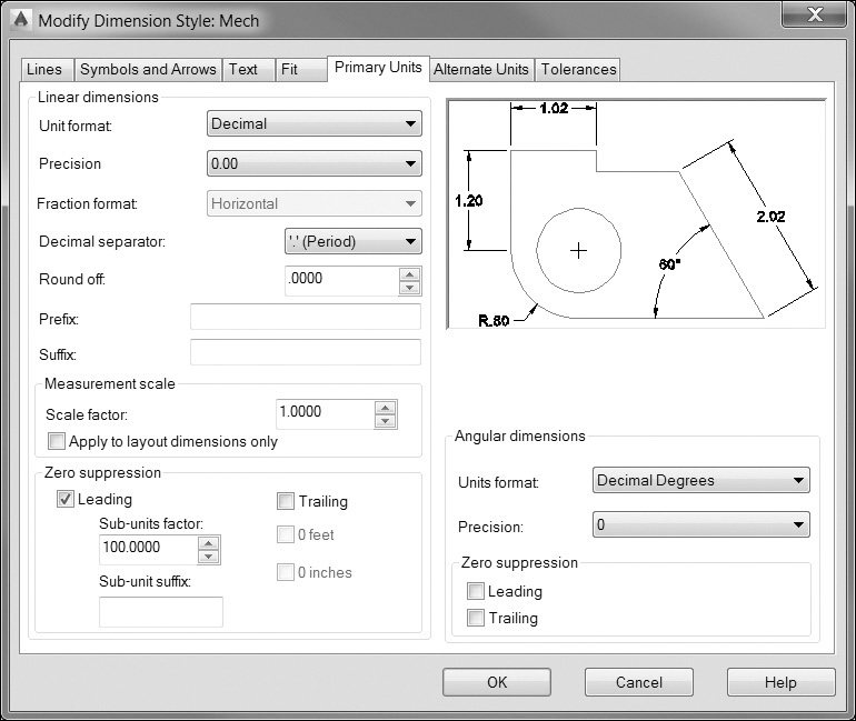
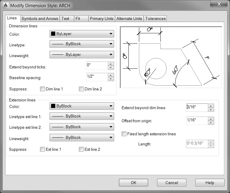
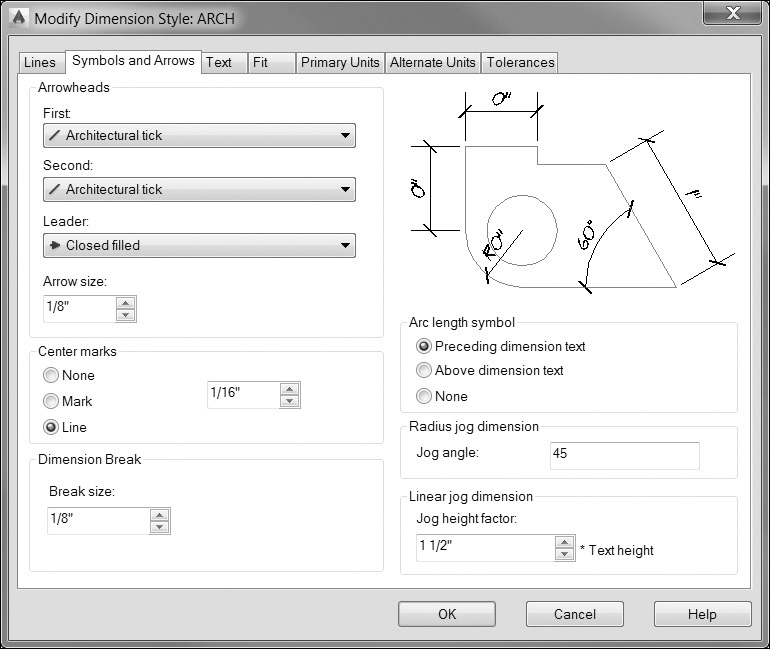
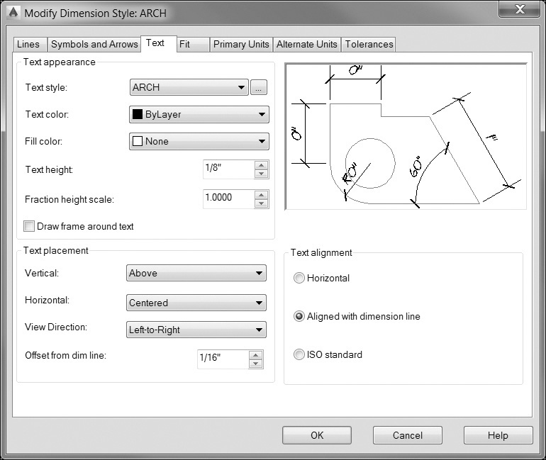
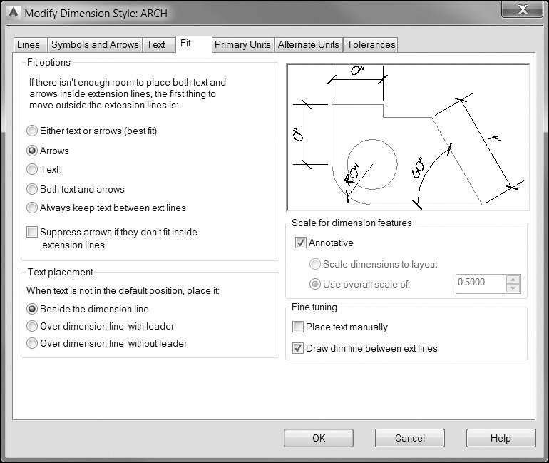
4. Dimension the graphic scales as shown in Figure 13-105 using the dimension style Standard on the layer A-Anno-Dims.
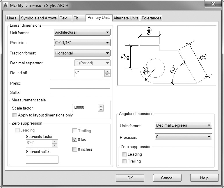
5. Save the drawing to a template file as Architectural D-Size.DWT.
![]() Project 13-4: Optical Mount—English Units, continued from Chapter 8 [INTERMEDIATE]
Project 13-4: Optical Mount—English Units, continued from Chapter 8 [INTERMEDIATE]
1. Open drawing P8-2 from Chapter 8.
2. Create a dimension style called Mech based on the Standard dimension style. Use the settings shown in Figures 13-95 through 13-99. Hint: You can use DesignCenter to drag and drop the dimension style from the mechanical drawing templates.
3. Set the Annotation Scale to 2:1 on the status bar.
4. Add the dimensioning shown in Figure 13-106. Hint: Use the QDIM command to create ordinate dimensioning.
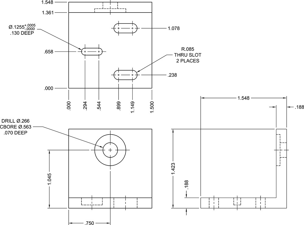
5. Save the drawing as P13-4.
![]() Project 13-5: Residential Architectural Plan, continued from Chapter 11 [ADVANCED]
Project 13-5: Residential Architectural Plan, continued from Chapter 11 [ADVANCED]
1. Open drawing P11-5 from Chapter 11.
2. Create a dimension style called ARCH. Use the settings shown in Figures 13-100 through 13-104. On the Fit tab, select the Annotative scale setting check box in the Scale for dimension features area to turn on annotation scaling.
3. Set the Annotation Scale to 1/4″ = 1′-0″ on the status bar.
4. Add the dimensions shown in Figure 13-107.
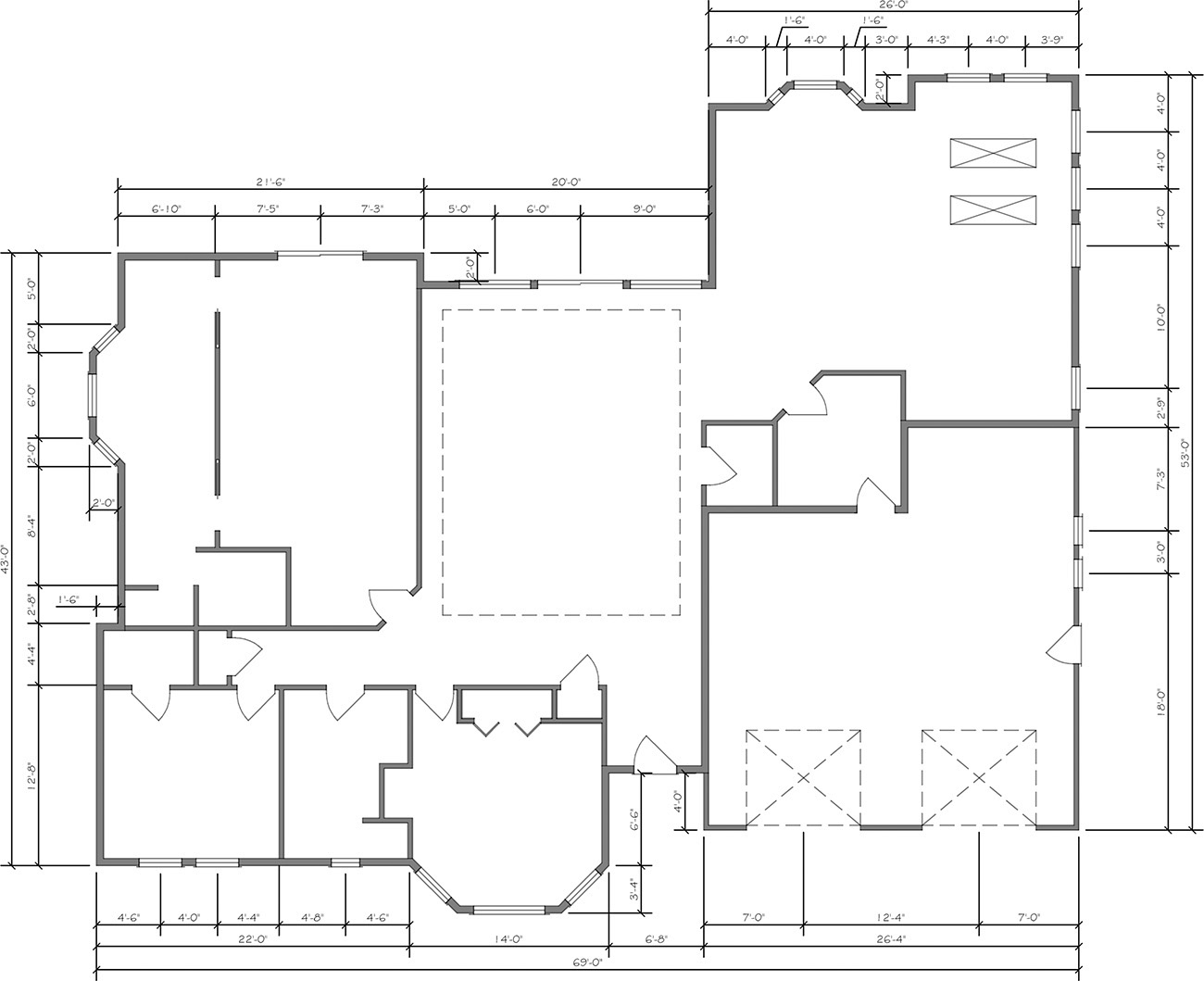
5. Save your drawing as P13-5.