
Chapter 16. Blocks and Block Attributes
• Create and insert blocks
• Understand the difference between a block definition and a block reference
• Explore the different types of blocks
• Create unit blocks that can be inserted with different x and y scale factors
• Manage block object properties such as layer, color, linetype, and lineweight
• Understand the significance of creating blocks on Layer 0
• Insert drawing files as blocks using Windows Explorer
• Create a drawing file (DWG) out of an internal block
• Create and update block attributes
• Extract block attributes to an AutoCAD table or external file
• Use DesignCenter to insert blocks
• Use and customize tool palettes
• Introduction to dynamic blocks
• Use Content Explorer to browse DWG files to locate and insert drawing information
Introduction
Blocks, also referred to as symbols, are one of the most valuable features in AutoCAD. A block is a named collection of AutoCAD objects treated as a single complex object that can be inserted in a drawing one or more times. Blocks provide the following benefits and features:
• Provide the ability to reuse drawing information repeatedly in one or more drawings
• Increase drawing uniformity and consistency
• Promote and help maintain drafting standards
• Reduce amount of time and effort to update and revise drawings
• Add intelligence to drawings
Blocks can be made from practically any type of AutoCAD objects including lines, circles, text, dimensions, and even hatching. They may be as simple as a single line or as complex as a complete drawing. There are three basic types of blocks as shown in Figure 16-1:
• Annotation Detail bubbles, section marks, door/window tags
• Schematic Electrical symbols, plumbing symbols, weld symbols
• Real-Size Furniture, doors/windows, plumbing fixtures
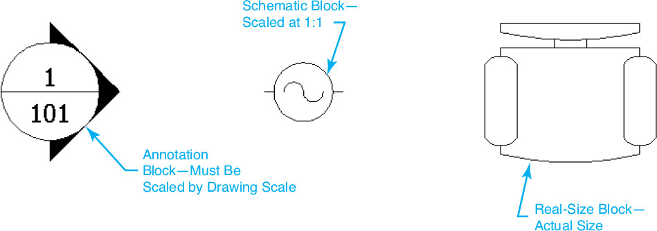
Annotation blocks need to be scaled up or down when they are inserted to account for the drawing scale, just like text and dimensions. For instance, a detail bubble drawn with a 1/2″-diameter circle as shown in Figure 16-1 would have to be scaled up by 48 in a drawing with the scale of 1/4″ = 1′-0″ in order to plot at the correct size.
Tip
It is possible to make a block annotative so it scales up or down automatically using the current annotation scale.
Schematic blocks are created at the size they will plot so that you can create schematic drawings at a scale of 1:1. For instance, the electrical symbol in Figure 16-1 is drawn with a 1/4″ diameter so that it can easily be located in a schematic drawing created on a 1/4″ or 1/8″ grid layout.
Real-size blocks are created at the actual size that the objects exist in the real world so that they can be used to accurately lay out a drawing. For instance, a 2′-0″ wide chair is drawn 24″ wide so that when it is located on a floor plan it represents the actual furniture.
It is even possible to attach dynamic intelligent text referred to as a block attribute that can be updated when a block is inserted or anytime later.
block attribute: A dynamic text-like object that can be included in a block definition to store alphanumeric data.
Note
Like other complex objects, a block can be converted back into its original subobjects using the EXPLODE command. Using the EXPLODE command with blocks is examined later in this chapter.
Existing block attributes can be extracted directly to an AutoCAD table so that you can automatically create schedules, parts lists, bills of materials, and other tabular type information. In fact, block attributes can even be extracted to an external text file, spreadsheet, or database so that the attribute information can be shared with others, used to generate reports, and used to perform other tasks.
As you can see, blocks are very useful. The following sections explain how to exploit the power of blocks and block attributes in your AutoCAD drawings.
Creating Blocks
The named group of AutoCAD objects that make up a block is referred to as a block definition.
block definition: A user-defined collection of drawing objects assigned a base point and a name that is stored centrally in a drawing.
Create Block |
|
Ribbon & Panel: |
Insert Block Definition
|
Menu: |
Draw Block | Make... |
Command Line: |
BLOCK BMAKE |
Command Alias: |
B |

Every time a block is inserted in a drawing it refers back to the centrally located block definition. In fact, when a block is inserted in a drawing, it is referred to as a block reference because it refers back to the block definition to determine its appearance and other properties.
block reference: An instance of a block definition inserted in a drawing that references the central block definition drawing data.
Note
It is possible to create blocks that are made up of other blocks. Creating a block within a block is a concept referred to as block nesting because one block is nested inside another block.
All that is stored with the block reference is the block’s insertion point, scale (x, y, and z), and rotation angle. The rest of the information is derived from the block definition. This arrangement provides a couple of advantages. One advantage is that the drawing size is reduced because the block definition is centrally stored in one place, regardless of how many references of the block exist in a drawing. The other advantage is that if you update a block definition, all references to that block definition in a drawing are automatically updated, regardless of how many references there are.
Creating a new block definition is easy. You simply draw the objects you want the block to consist of using standard drawing techniques and then start the BLOCK command so you can select the objects and give them a descriptive name that you can reference later.
The BLOCK Command
The BLOCK command creates a block definition using the objects you select with the name specified via the Block Definition dialog box shown in Figure 16-2.
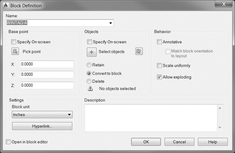
The Name: list box is where you enter the desired block name. The name can be up to 255 characters long and can include letters, numbers, or blank spaces. Typically, you want to use a descriptive name that reflects the block’s contents and/or usage.
Note
Do not use the block names AVE_RENDER, DIRECT, LIGHT, OVERHEAD, RM_SDB, or SH_SPOT. These names are reserved for special AutoCAD objects.
Selecting an existing block name from the list will redefine all references to that block in the drawing if you make any changes. Redefining blocks is explained later in this chapter.
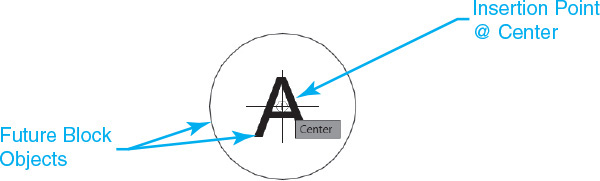
The Base point area allows you to specify an insertion point for the block. This point is used to locate the block in the drawing when it is inserted later. The default insertion point is 0,0,0. You can either enter the x, y, and z coordinate values directly in their respective text boxes or pick a point in your drawing by selecting the Pick point button. The Pick point button temporarily closes the Block Definition dialog box so that you can pick a point in the drawing as shown in Figure 16-3.
Tip
Typically, you should rely on object snaps to snap to a key point on the objects that comprise the block. For instance, you might select the center point if you were creating a detail bubble block or the endpoint at a corner of a desk block.
The Objects area allows you to select the objects to include in the new block definition if there are none already selected in the drawing, as well as to indicate what to do with the selected objects after the block definition is created.
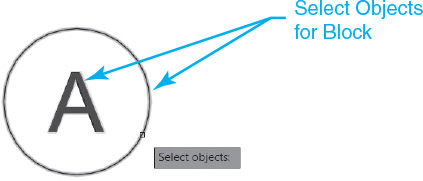
The Select objects button closes the Block Definition dialog box temporarily so you can select objects in the drawing as shown in Figure 16-4.
Note
If no objects are selected, the No objects selected warning shown in Figure 16-2 is displayed at the bottom of the Objects area. Otherwise, the number of objects that are currently selected is displayed.
You can use any standard selection process. When you finish selecting objects, press <Enter> to redisplay the Block Definition dialog box and continue defining the block. Pressing the <Esc> key when selecting objects will deselect the objects so that nothing is selected and redisplay the Block Definition dialog box.
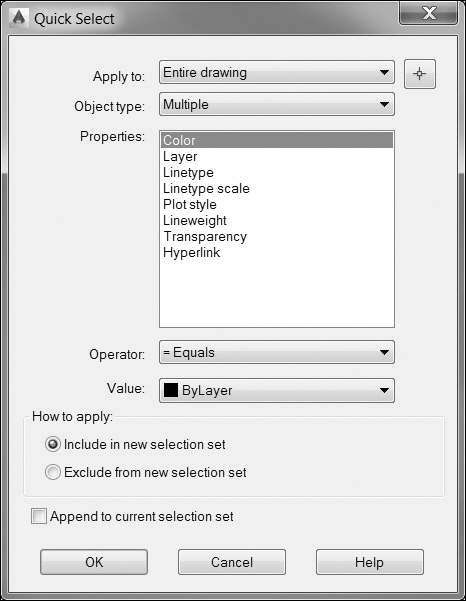
The QuickSelect button closes the Block Definition dialog box temporarily and displays the Quick Select dialog box shown in Figure 16-5 so you can select objects by filtering one or more object properties.
The other three options in the Objects area directly below the Select objects button determine what happens to the selected objects after the block is created:
• Retain Retains the original selected objects in the drawing without doing anything
• Convert to block (default) Converts the selected objects to a block reference “in-place”
• Delete Deletes all the selected objects after the block is created so that they no longer exist
Tip
If you use the Delete option by accident, you can use the OOPS command to undelete the block subobjects. Type OOPS if <Enter> immediately after the block is created in order to return the original block subobjects to your drawing.
The Settings area at the bottom left is where you specify different settings for the block.
The Block unit list box lists the different possible insertion units for the block. If you insert a block that is created with different block drawing units than the insertion scale units currently set for the drawing, the block is automatically scaled up or down according to the scale factor equivalent of the ratio between the different unit systems.
Note
The insertion scale units are set via the Drawing Units dialog box, which can be displayed by selecting Units from the Drawing Utilities menu on the big A application menu or using the UNITS command.
The Hyperlink... button displays the Insert Hyperlink dialog box so that you can associate a hyperlink with the block definition. Hyperlinks can be attached to almost any AutoCAD object so that it is possible to link objects to websites and even other documents.
The Behavior area at the top right is where you control what happens after a block is inserted.
The Annotative check box indicates whether or not the block can be scaled up and down automatically using the current annotation scale.
The Scale uniformly check box indicates whether or not the block reference can be nonuniformly scaled when it is inserted so that the x, y, and z scales are not all equal.
The Allow exploding check box indicates whether or not the block reference can be exploded when it is inserted or afterward.
Note
The block definition is created in the current drawing only. To use the block in any other drawing, you must first export it to a separate drawing file using the WBLOCK command explained later in this chapter.
The Description text box allows you to input a text description for the block that appears in the DesignCenter block drawing content management tool discussed later in this chapter.
The Open in block editor check box opens the current block definition in the Block Editor after you select OK. The Block Editor is described briefly later in this chapter.
After you have entered a name for the block, selected one or more objects, and specified the desired settings described above, select OK to close the dialog box and create the block.
Block Object Properties
When you insert a block, the block reference assumes the current object properties (layer, color, linetype, lineweight) just like other AutoCAD objects. Be aware that the current properties are assigned to the overall complex block reference only. The object properties of the subobjects that make up the block are determined by how the objects were originally created before they were made into a block.
There are three different techniques for controlling the properties of a block’s subobjects that result in the following effects when the block is inserted:
• Create subobjects on Layer 0 with the color, linetype, and lineweight set to ByLayer
• Create subobjects on any layer other than 0
• Create subobjects using the ByBlock property set for color, linetype, or lineweight
Creating Blocks on Layer 0
Creating block subobjects on Layer 0 with object properties set to ByLayer is the most popular approach to creating blocks because it provides the most flexibility. Blocks with subobjects created on Layer 0 have the special ability to assume the current object properties when they are inserted. This allows you to create one block that can be used in multiple scenarios based on the layer that is current when the block is inserted.
Hard-Coding a Block’s Object Properties
Creating block subobjects on any layer other than 0 locks the subobjects on the layer on which they were created so that the subobjects always maintain their original properties regardless of what layer or other properties are current when the block is inserted. This approach provides the least amount of flexibility because the block’s subobjects are always located on the layer on which they were created regardless of the current layer and object properties in the drawing when the block is inserted. However, this hard-coded approach can have its uses, especially if standards dictate that a particular layer should be maintained for the life of a drawing.
Using the ByBlock Object Property
The ByBlock property allows you to create block subobjects that will assume the current color, linetype, lineweight, or transparency property when the block is inserted. Normally, a block and its subobjects ignore the color, linetype, lineweight, and transparency properties when the block is inserted. If you create a block subobject with any of these properties set to ByBlock, the subobject will assume the current setting for the property during the insertion process. For instance, setting a line’s color property to ByBlock and including it in a block definition forces the line to assume the current color when the block is inserted. If the current color setting is red, then the line subobject is red. The same logic applies to the linetype and lineweight properties.
![]() Start a new drawing using the acad.dwt drawing template.
Start a new drawing using the acad.dwt drawing template.
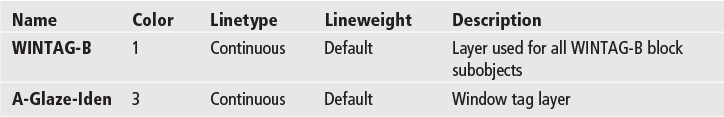
![]() Create the following layers:
Create the following layers:
![]() Create the “A” window tag shown in Figure 16-6 on Layer 0.
Create the “A” window tag shown in Figure 16-6 on Layer 0.
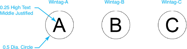
![]() Create the “B” window tag shown in Figure 16-6 on layer WINTAG-B.
Create the “B” window tag shown in Figure 16-6 on layer WINTAG-B.
![]() Create the “C” window tag shown in Figure 16-6 on Layer 0 with the color, linetype, and lineweight properties all set to ByBlock.
Create the “C” window tag shown in Figure 16-6 on Layer 0 with the color, linetype, and lineweight properties all set to ByBlock.
![]() Start the BLOCK command to display the Block Definition dialog box.
Start the BLOCK command to display the Block Definition dialog box.
![]() Enter the name WINTAG-A in the Name: list box.
Enter the name WINTAG-A in the Name: list box.
![]() Select the Pick point button in the Base point area.
Select the Pick point button in the Base point area.
![]() Select the center point of the “A” window tag circle using the Center object snap.
Select the center point of the “A” window tag circle using the Center object snap.
![]() Select the Select objects button in the Objects area.
Select the Select objects button in the Objects area.
![]() Select the “A” window tag circle and text, and press <Enter> to return to the Block Definition dialog box.
Select the “A” window tag circle and text, and press <Enter> to return to the Block Definition dialog box.
![]() Make sure that the Convert to block button is selected.
Make sure that the Convert to block button is selected.
![]() Select the Annotative check box in the Behavior area.
Select the Annotative check box in the Behavior area.
![]() Select OK to create the block.
Select OK to create the block.
![]() Repeat steps 6 through 14 to create blocks named WINTAG-B and WINTAG-C for the “B” window tag and the “C” window tag, respectively.
Repeat steps 6 through 14 to create blocks named WINTAG-B and WINTAG-C for the “B” window tag and the “C” window tag, respectively.
![]() Save the drawing as CH16_EXERCISE1.
Save the drawing as CH16_EXERCISE1.
Inserting Blocks
As mentioned earlier, when you insert a block, it creates a block reference. Remember that the information about the objects that make up the block and what the block looks like is determined by the block definition explained in the previous section. All that you need to specify when inserting a block is the following:
• Block name
• Insertion point
• x, y, and z scale
• Rotation angle
In fact, besides the standard object properties such as layer, color, linetype, and transparency discussed later, this constitutes the majority of the information that is stored with the block reference. This is evident when you list a block reference using the AutoCAD LIST command:
BLOCK REFERENCE Layer: “0”
Space: Model space
Handle = a4
Block Name: “WINTAG-A”
at point, X = 0.0000 Y = 0.0000 Z = 0.0000
X scale factor: 1.0000
Y scale factor: 1.0000
rotation angle: 0
Z scale factor: 1.0000
InsUnits: Inches
Unit conversion: 1.0000
Scale uniformly: No
Allow exploding: Yes
Remember that a block reference assumes the object properties that are current when the block is inserted just like any other AutoCAD object. However, how the object properties affect the appearance of the block reference is dependent on how the block was created as explained earlier in the section “Creating Blocks.”
Insert Block |
|
Ribbon & Panel: |
Insert Block
|
Menu: |
Insert Block... |
Command Line: |
INSERT |
Command Alias: |
I |

The INSERT Command
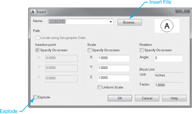
The INSERT command allows you to insert a block reference by specifying the block name, insertion point, scale, and rotation angle via the Insert dialog box shown in Figure 16-7.
The Name: list box lists the names of all the blocks defined in a drawing that can be inserted.
The Browse... button displays the standard Select Drawing File dialog box so you can select a block or drawing file to insert.
The Path: label specifies the path to the block if you select an external drawing file using the Browse... button above.
The Locate using Geographic Data check box will insert the block using geographic data as the reference. This option is enabled only if both the block and the current drawing have geographic data.
The Preview window displays a preview of the specified block to insert. A lightning bolt icon in the lower-right corner of the preview indicates that the block is dynamic.
The Insertion point area allows you to specify the insertion point for the block. You can either pick a point in the drawing after you select OK (default), or you can specify the coordinate position in the X:, Y:, and Z: text boxes. The Specify On-screen check box toggles between the two methods.
The Scale area allows you to specify the x, y, and z scale factors for the inserted block. You can either enter the scale factors in the X:, Y:, and Z: text boxes (default), or you can enter the scale factors after you select OK. The Specify On-screen check box toggles between the two methods.
Note
It is possible to insert an external drawing file (DWG) file from anywhere on your computer or network using the Browse... button. Inserting external drawing files is explained in detail later in this chapter.
The Uniform Scale check box forces a single scale value for the X-, Y-, and Z-axes. When the Uniform Scale check box is selected, the y and z scales default to the value specified for x.
The Rotation area allows you to specify the rotation angle for the inserted block in the current UCS. You can either enter the rotation angle in the Angle: text box (default), or you can enter the rotation angle after you select OK. The Specify On-screen check box toggles between the two methods.
The Block Unit area displays information about the block units. The Unit: label indicates the insert units for the block. The Factor: displays the unit scale factor, which is calculated based on the insert units of the block and the drawing units. Neither of these settings can be changed in the Insert dialog box.
The Explode check box explodes the block immediately after it is inserted. It is possible to specify a uniform scale factor only when the Explode check box is selected.
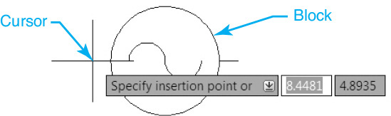
After all the desired settings have been specified, select OK to insert the block as shown in Figure 16-8.
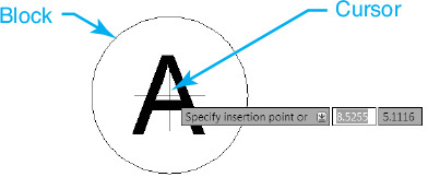
Figure 16-8 shows a block being inserted using the default settings, which prompt you to Specify insertion point or ![]() on-screen during the insertion process.
on-screen during the insertion process.
If the Specify On-screen check box is selected for the Scale settings, AutoCAD prompts you to Enter X scale factor, specify opposite corner, or ![]() so that you can either enter the desired scale for the X-axis at the keyboard or pick a corner point in your drawing that dynamically defines both the x and y scales. The default scale factor is always 1.
so that you can either enter the desired scale for the X-axis at the keyboard or pick a corner point in your drawing that dynamically defines both the x and y scales. The default scale factor is always 1.
If you enter an x scale and press <Enter>, AutoCAD then prompts you to Enter Y scale factor <use X scale factor>: ![]() . You can either press <Enter> so that the x and y scales are equal, or you can enter a different scale factor to create a nonuniformly scaled block. Nonuniformly scaled blocks are discussed in the next section.
. You can either press <Enter> so that the x and y scales are equal, or you can enter a different scale factor to create a nonuniformly scaled block. Nonuniformly scaled blocks are discussed in the next section.
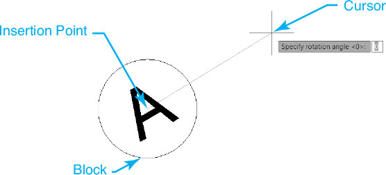
If the Specify On-screen check box is selected for the Rotation settings, AutoCAD prompts you to Specify rotation angle <0>: so that you can either enter the desired rotation angle at the keyboard or pick a point in your drawing that dynamically defines the angle using the insertion point as the angle base point as shown in Figure 16-9.
Exercise 16-2 Inserting Blocks
![]() Continue from Exercise 16-1.
Continue from Exercise 16-1.
![]() Set the current layer to A-Glaze-Iden via the Layers drop-down list.
Set the current layer to A-Glaze-Iden via the Layers drop-down list.
![]() Set the current color to Blue via the Properties panel on the Home tab of the ribbon.
Set the current color to Blue via the Properties panel on the Home tab of the ribbon.
![]() Use the INSERT command to insert the WINTAG-A, WINTAG-B, and WINTAG-C blocks anywhere in the drawing so that you can see all three block references in the drawing window.
Use the INSERT command to insert the WINTAG-A, WINTAG-B, and WINTAG-C blocks anywhere in the drawing so that you can see all three block references in the drawing window.
![]() Compare how the object properties are different for each block reference.
Compare how the object properties are different for each block reference.
![]() Turn on the Automatically add scales to annotative objects when the annotation scale changes button on the right side of the status bar.
Turn on the Automatically add scales to annotative objects when the annotation scale changes button on the right side of the status bar.
![]() Change the Annotation Scale to 1:2.
Change the Annotation Scale to 1:2.
![]() Insert one of the WINTAG blocks.
Insert one of the WINTAG blocks.
![]() Change the Annotation Scale to 2:1.
Change the Annotation Scale to 2:1.
![]() Insert another WINTAG block.
Insert another WINTAG block.
![]() Save the drawing.
Save the drawing.
Nonuniformly Scaled Unit Blocks
If the Uniform Scale check box was not selected when the block was created, you can specify different x, y, and z scale factors when a block is inserted so that the block can be scaled along a single axis. In fact, this is a technique that is used to create what are known as unit blocks.
unit block: A block or symbol drawn within a 1 × 1 unit square that is inserted in the drawing with different x and y scales to achieve different final sizes.
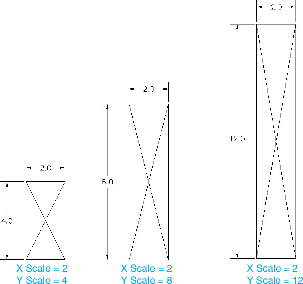
Unit blocks can be scaled along one axis so that one block definition can serve multiple purposes. A classic example is a structural lumber section, which is typically represented by a nominally sized rectangle with a cross through it (see Figure 16-10). Creating the lumber section as a unit block allows you to specify different x and y scales when the block is inserted so that different lumber sizes can be created as shown in Figure 16-10.
Exercise 16-3 Nonuniformly Scaled Unit Blocks
![]() Start a new drawing using the acad.dwt drawing template.
Start a new drawing using the acad.dwt drawing template.
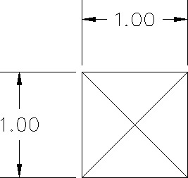
![]() Create the unit block drawing shown in Figure 16-11.
Create the unit block drawing shown in Figure 16-11.
![]() Use the BLOCK command to create a block named STUD that consists of the line work created in step 2 with a base point at the lower left-hand corner.
Use the BLOCK command to create a block named STUD that consists of the line work created in step 2 with a base point at the lower left-hand corner.
![]() Start the INSERT command to display the Insert dialog box.
Start the INSERT command to display the Insert dialog box.
Note
The lumber sizes used in the examples in this section are shown as nominal sizes and not actual sizes for the sake of simplicity.
![]() Select STUD from the Name: list box.
Select STUD from the Name: list box.
![]() Make sure the Specify On-screen check box is unselected in the Scale area.
Make sure the Specify On-screen check box is unselected in the Scale area.
![]() Set the X: scale to 2.0.
Set the X: scale to 2.0.
![]() Set the Y: scale to 4.0.
Set the Y: scale to 4.0.
![]() Select OK to insert the 2 × 4 stud anywhere in your drawing.
Select OK to insert the 2 × 4 stud anywhere in your drawing.
![]() Start the INSERT command to display the Insert dialog box.
Start the INSERT command to display the Insert dialog box.
![]() Select STUD from the Name: list box if not selected.
Select STUD from the Name: list box if not selected.
![]() Set the X: scale to 2.0.
Set the X: scale to 2.0.
![]() Set the Y: scale to 8.0.
Set the Y: scale to 8.0.
![]() Select OK to insert the 2 × 8 stud anywhere in your drawing.
Select OK to insert the 2 × 8 stud anywhere in your drawing.
![]() Start the INSERT command to display the Insert dialog box.
Start the INSERT command to display the Insert dialog box.
![]() Select STUD from the Name: list box if not selected.
Select STUD from the Name: list box if not selected.
![]() Set the X: scale to 2.0.
Set the X: scale to 2.0.
![]() Set the Y: scale to 12.0.
Set the Y: scale to 12.0.
![]() Select OK to insert the 2 × 12 stud anywhere in your drawing.
Select OK to insert the 2 × 12 stud anywhere in your drawing.
![]() Your drawing should look like Figure 16-10.
Your drawing should look like Figure 16-10.
![]() Save the drawing.
Save the drawing.
Exploding Blocks
As mentioned earlier in the Introduction, a block reference is considered a complex object just like a polyline, boundary hatch, or dimension. If the Allow exploding check box was selected when the block was created, you can explode a block back into its original individual subobjects either after it is inserted using the EXPLODE command or when it is inserted by selecting the Explode check box in the Insert dialog box shown in Figure 16-7.
Tip
Typically, you do not want to explode blocks because you lose all the advantages of using them in the first place. Not only can you no longer automatically update an exploded block using the techniques explained later in this chapter, but you also increase the size of the drawing because each subobject is added as a new object and is no longer simply a reference.
Inserting a Drawing File as a Block
It is possible, and actually quite common, to insert an entire drawing file (DWG) as a block. When you insert a drawing file, a block definition with the same name as the file is automatically created using all the information in the drawing file.
Note
When you insert a drawing file as a block, only model space information is included. Objects located in paper space are ignored.
There are a couple of ways to insert a drawing file as a block. To insert a drawing file via the Insert dialog box explained earlier, select the Browse... button shown in Figure 16-7 to display the Select Drawing File dialog box shown in Figure 16-12.
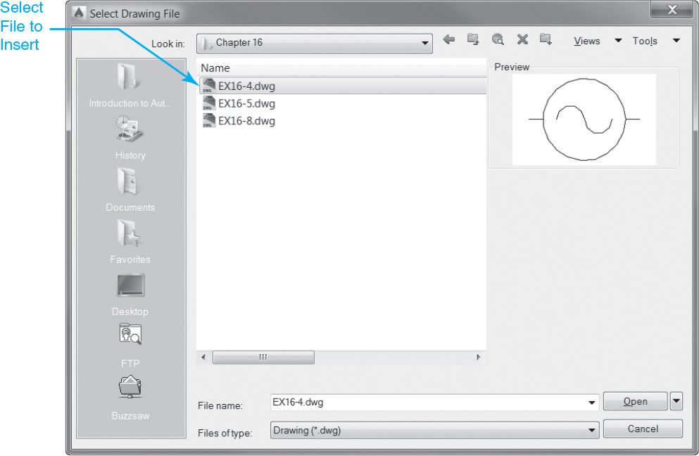
Find the file you want to insert and select the Open button. A block definition with the same name as the drawing file is added to the Name list box, and it becomes the current block to insert as shown in Figure 16-13.
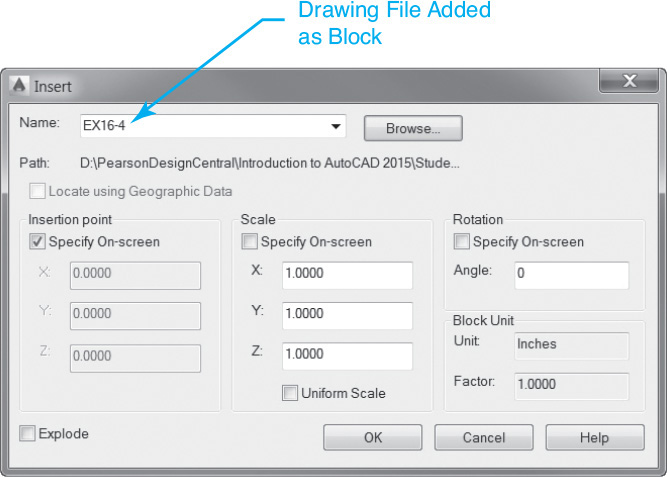
Once a drawing has been selected and it has been made a block definition, the exact same settings can be specified. You can select OK to insert the block.
Note
When you insert a drawing file, all the nongraphical named information defined in the drawing, such as layers, linetypes, text styles, dimension styles, etc., comes along for the ride so that any named information defined in the original drawing becomes part of the current drawing.
Tip
By default, the insertion base point for a drawing file inserted as a block is the coordinate location 0,0,0 in the original drawing file. You can change the insertion base point by opening the drawing file and using the BASE command to set it to another location. Don’t forget to save the drawing.
Exercise 16-4 Inserting a Drawing File as a Block
![]() Continue from Exercise 16-3.
Continue from Exercise 16-3.
![]() Start the INSERT command to display the Insert dialog box.
Start the INSERT command to display the Insert dialog box.
![]() Select the Browse... button to display the Select Drawing File dialog box and locate the EX16-4.DWG drawing file in the student data files.
Select the Browse... button to display the Select Drawing File dialog box and locate the EX16-4.DWG drawing file in the student data files.
To access student data files, go to www.pearsondesigncentral.com.
![]() Select the EX16-4.DWG file, and select the Open button to return to the Insert dialog box.
Select the EX16-4.DWG file, and select the Open button to return to the Insert dialog box.
![]() Select OK to insert the block anywhere in the drawing as shown in Figure 16-14.
Select OK to insert the block anywhere in the drawing as shown in Figure 16-14.
![]() Save the drawing.
Save the drawing.
Using Windows Explorer to Insert a Drawing File
You can use Windows® Explorer to drag and drop a drawing file directly into the current drawing. You can start Windows Explorer a number of ways including by double-clicking on the My Computer icon on the Windows desktop, by right-clicking on the Windows Start button and selecting Explore from the menu, or even by typing the EXPLORE command in AutoCAD.
In order to use drag-and-drop techniques, you must be able to have both AutoCAD and Explorer visible on your computer at the same time, as shown in Figure 16-15.
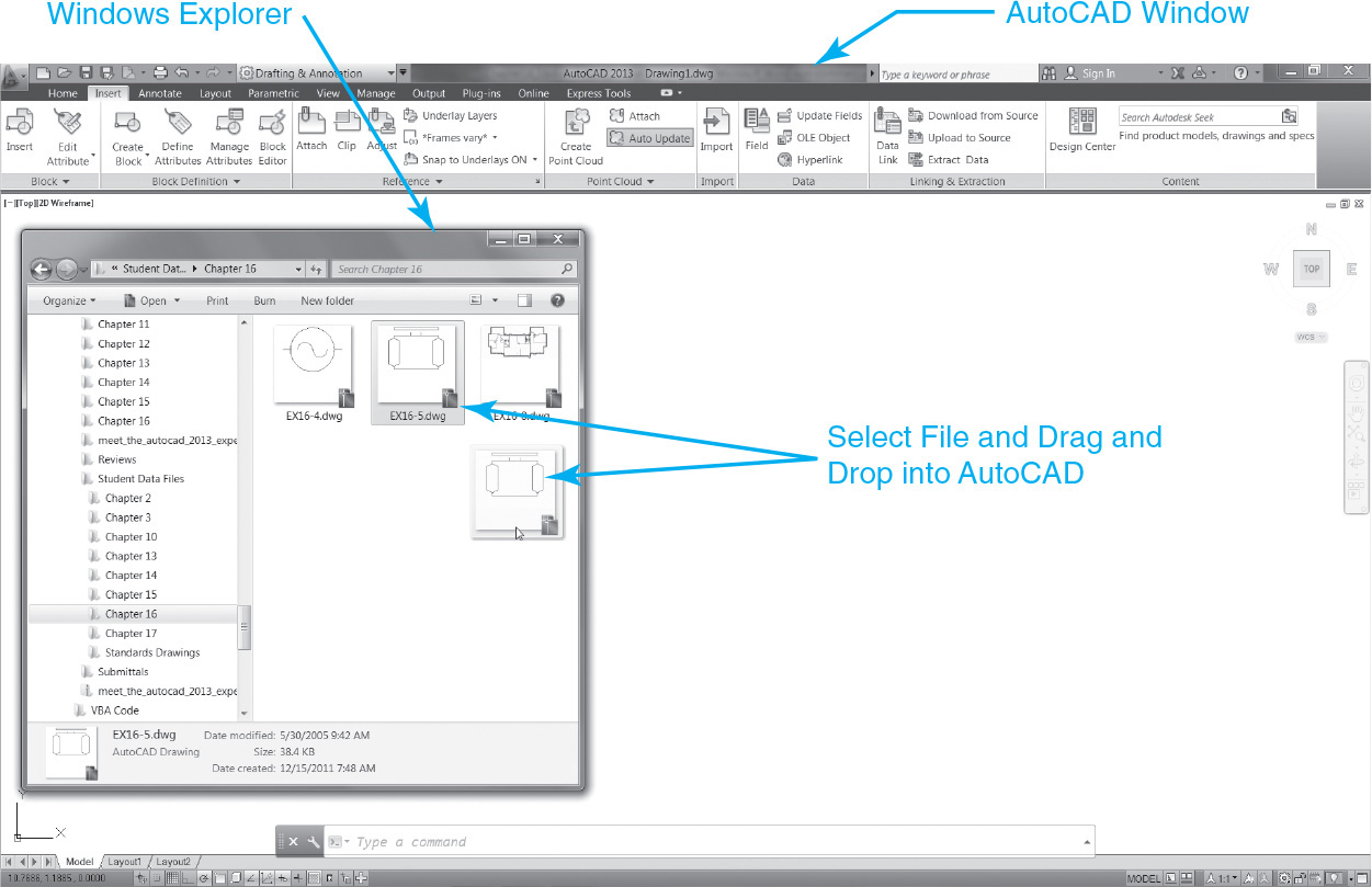
If you select a file with the left mouse button and drag and drop it into your drawing, the same insertion point, scale factor, and rotation angle command prompts are displayed as if the Specify On-screen check boxes were selected in the Insert dialog box described earlier.
If you select a file with the right mouse button and drag and drop it into your drawing, the shortcut menu shown in Figure 16-16 is displayed.
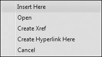
Using the shortcut menu, you can elect to do one of the following:
• Insert Here Inserts the file as a block the same as above
• Open Opens the drawing file in a new window
• Create Xref Attaches the drawing as an xref
• Create Hyperlink Here Creates a hyperlink to the drawing on the object you select
• Cancel Cancels drag-and-drop operation
Exercise 16-5 Using Windows Explorer to Insert a Drawing File
![]() Continue from Exercise 16-4.
Continue from Exercise 16-4.
![]() Start Windows Explorer using one of the techniques explained above.
Start Windows Explorer using one of the techniques explained above.
![]() Set up your computer display so that the AutoCAD drawing window and Windows Explorer window are both visible, similar to the display shown in Figure 16-15.
Set up your computer display so that the AutoCAD drawing window and Windows Explorer window are both visible, similar to the display shown in Figure 16-15.
![]() In Windows Explorer, locate the EX16-5.DWG drawing file in the student data files.
In Windows Explorer, locate the EX16-5.DWG drawing file in the student data files.
To access student data files, go to www.pearsondesigncentral.com.
![]() Select the EX16-5.DWG drawing file with your left mouse button, and drag and drop it into the current drawing.
Select the EX16-5.DWG drawing file with your left mouse button, and drag and drop it into the current drawing.
![]() Select the EX16-5.DWG drawing file with your right mouse button, and drag and drop it into the current drawing.
Select the EX16-5.DWG drawing file with your right mouse button, and drag and drop it into the current drawing.
![]() Select Insert Here from the shortcut menu.
Select Insert Here from the shortcut menu.
![]() Select an insertion point in the drawing, and press <Enter> three times to accept the defaults for the x scale (1), y scale (1), and rotation angle (0).
Select an insertion point in the drawing, and press <Enter> three times to accept the defaults for the x scale (1), y scale (1), and rotation angle (0).
![]() Save the drawing.
Save the drawing.
Exporting Blocks
As mentioned earlier in the “Creating Blocks” section, by default, a block definition is stored only in the drawing in which it is created. In order to use the block in another drawing, you must first export it to a drawing file (DWG). You can then insert it using the techniques explained above.
The WBLOCK Command
The WBLOCK command, short for “write block,” writes a block definition to an external drawing file (DWG) with the file name and location you specify using any of the following methods:
• Write an existing block definition that is already defined internally in a drawing
• Create a new block definition and write the block to an external drawing file
• Create a new block definition using all the information in the drawing, and write the block to an external drawing file
Write Block |
|
Ribbon & Panel: |
Insert | Block Definition
|
Menu: |
None |
Command Line: |
WBLOCK |
Command Alias: |
W |

Starting the WBLOCK command displays the Write Block dialog box shown in Figure 16-17. The Source area is the main area of the dialog box used to specify how to create the block.
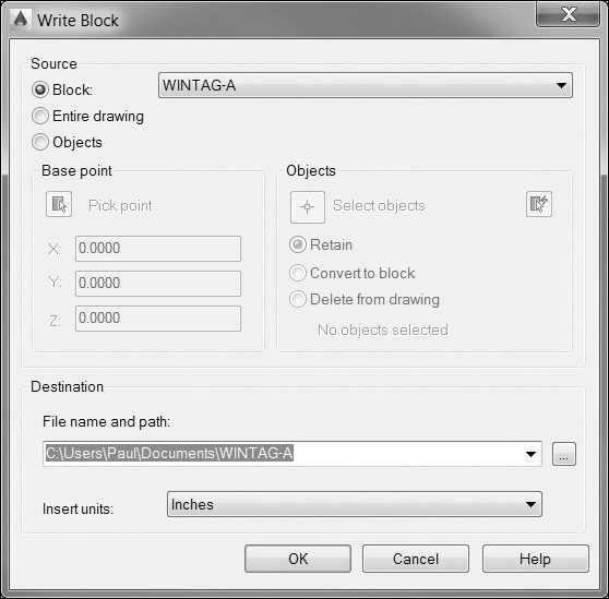
The Block option allows you to select a block that has already been defined in the drawing from the list on the right. This option and the list are disabled if there are no blocks defined in the drawing. The Entire drawing option creates a block out of the entire drawing and writes it out to a file.
Tip
Using WBLOCK to create a block out of the entire drawing and write it to a file is an old trick used to quickly purge a drawing of all its unreferenced drawing information such as layers, linetypes, text styles, dimension styles, other blocks, and so on, so that the file size is reduced.
The Objects option allows you to create a new block on the fly and write it out to an external file using the exact same techniques as the BLOCK command explained earlier in the chapter. See the earlier section “Creating Blocks” for complete, detailed information about creating a block from scratch.
The Base point area allows you to specify a base point for the block. The default value is 0,0,0.
The Select objects button closes the Write Block dialog box temporarily so you can select objects in the drawing as shown earlier in Figure 16-4. The QuickSelect button closes the Write Block dialog box temporarily and displays the Quick Select dialog box shown earlier in Figure 16-5 so you can select objects by filtering on one or more object properties.
The other three options in the Objects area directly below the Select objects button determine what happens to the selected objects after the block is created:
• Retain (default) Retains the original selected objects in the drawing without doing anything
• Convert to block Converts the selected objects to a block reference “in-place”
• Delete from drawing Deletes all the selected objects after the block is created so that they no longer exist
The Destination area is where you specify the file name and location and the units of measurement to be used when the block is inserted.
The File name and path: text box allows you to enter the file name and path where the block will be saved.
Selecting the [...] button displays the standard Browse for Drawing File dialog box so you can select a file or specify another drive and folder location. The selected file and location are displayed in the File name and path: text box above when you exit the dialog box by selecting the Save button.
The Insert units: list box lists the different possible insertion units for the block. If you insert a block that is created with different block drawing units from the insertion scale units currently set for the drawing, the block is automatically scaled up or down according to the scale factor equivalent of the ratio between the different unit systems.
Exercise 16-6 Using the WBLOCK Command to Export a Block
![]() Continue from Exercise 16-5.
Continue from Exercise 16-5.
![]() Start the WBLOCK command to display the Write Block dialog box.
Start the WBLOCK command to display the Write Block dialog box.
![]() Select the Block option in the Source area at the top of the dialog box.
Select the Block option in the Source area at the top of the dialog box.
![]() Select the WINTAG-A block from the Block list box.
Select the WINTAG-A block from the Block list box.
![]() Set the File name and path: setting in the Destination area to a folder location of your choice using the WINTAG-A.DWG file name, and select OK to export the block.
Set the File name and path: setting in the Destination area to a folder location of your choice using the WINTAG-A.DWG file name, and select OK to export the block.
![]() Draw a “D” window tag similar to the others with the same circle diameter and text height somewhere in the drawing.
Draw a “D” window tag similar to the others with the same circle diameter and text height somewhere in the drawing.
![]() Start the WBLOCK command to display the Write Block dialog box again.
Start the WBLOCK command to display the Write Block dialog box again.
![]() Select the Objects option in the Source area at the top of the dialog box.
Select the Objects option in the Source area at the top of the dialog box.
![]() Select the Pick point button in the Base point area.
Select the Pick point button in the Base point area.
![]() Select the center point of the “D” window tag circle you just created using the Center object snap.
Select the center point of the “D” window tag circle you just created using the Center object snap.
![]() Select the Select objects button in the Objects area.
Select the Select objects button in the Objects area.
![]() Select the “D” window tag circle and text, and press <Enter> to return to the Write Block dialog box.
Select the “D” window tag circle and text, and press <Enter> to return to the Write Block dialog box.
![]() Set the File name and path: setting in the Destination area to a folder location of your choice with the file name WINTAG-D.DWG and select OK to export the block.
Set the File name and path: setting in the Destination area to a folder location of your choice with the file name WINTAG-D.DWG and select OK to export the block.
![]() Save the drawing.
Save the drawing.
Block Attributes
As explained in the Introduction, an attribute is a text-like object included in a block definition that is used to store alphanumeric information. It can be either updated dynamically when a block is inserted or updated manually after the block is inserted later by selecting the block. Updated attribute data can then be used to automatically create tables or exported to external files using the Data Extraction wizard explained later in this chapter.
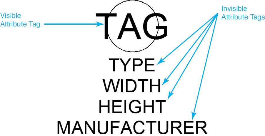
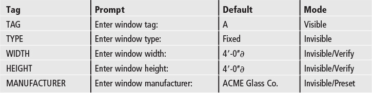
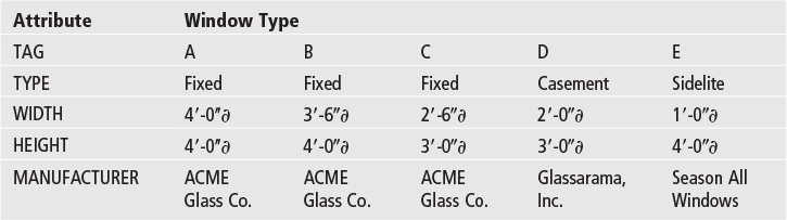
The key to an attribute is its tag, which is used to store and retrieve the attribute data. A tag is an attribute’s unique identifier, similar to a field in a database or a row/column in a spreadsheet. The tag allows you to specify which attributes to extract when you use the Data Extraction wizard. Tags are typically all uppercase and cannot include any spaces or special characters. They are typically given a descriptive name indicating the type of data they are storing. For example, the attribute tags for a window tag block that contains information about the window type, width, height, and manufacturer might be defined as shown in Figure 16-18.
Note
Attributes can be set to be invisible so that you can attach nongraphical information to a block that can be updated and extracted even though you can’t see it in the drawing and it doesn’t plot. This and other special attribute properties are discussed later in the section “Creating Attributes.”
Figure 16-18 shows what the window tag block looks like prior to being defined. Attributes that are defined to be invisible are not turned off until the block is defined and inserted as a block reference in the drawing as shown later in Figure 16-21.
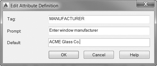
The other key parts of an attribute definition are its prompt and default value. The prompt is what you see when you insert the block so you know what type of information to enter. The default value is what the attribute is automatically set to if no information is entered. The attribute tag, prompt, and default value for the window tag block’s manufacturer attribute are shown in Figure 16-19.
After the block is defined and you insert it, you are automatically prompted to enter the attribute values either individually at the command prompt or en masse via the Edit Attributes dialog box shown in Figure 16-20.
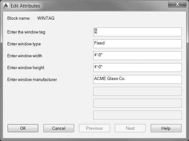
After the attribute values have been entered either via the Edit Attributes dialog box or at the command prompt, a block reference is created as shown in Figure 16-21.

Notice that the attributes that were defined as invisible are now no longer displayed, although it is possible to turn them on if necessary.
It is possible to update the attributes after the block is inserted using a number of different approaches, all of which are explained later in the section “Updating and Editing Attributes.” First, though, we need to create a block with some attributes.
Note
Attribute display is controlled via the Attributes panel on the Insert tab of the ribbon. The Display All setting turns all invisible attributes on and the Hide All setting turns off all attributes. The Retain Display setting displays attributes as they were originally defined. You can also use the ATTDISP command to control the same settings.
Creating Attributes
When working with attributes, you follow the same steps you would for creating a standard block. First you draw any line work and/or text that will make up the block, and then you can define the attributes. Attributes share many of the same properties as text, including the ability to assign text styles and fonts. When you add an attribute, you must also specify a justification and insertion point, similar to the manner in which you add single-line text.
Just like other AutoCAD objects, attributes also assume the current object properties such as layer, color, and linetype. Some organizations create attributes on their own individual layer so you can further control their visibility and appearance.
Ribbon & Panel: |
Insert Block Definition
|
Menu: |
Draw | Block | Define Attributes... |
Command Line: |
ATTDEF |
Command Alias: |
ATT |

For More Details
See Chapter 11 for more details about the different text properties and effects. See Chapter 6 for more details about managing object properties.
Attribute Definition
The ATTDEF command creates an attribute definition via the Attribute Definition dialog box shown in Figure 16-22.
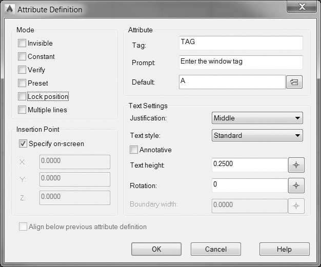
The Mode area is where you control the visibility and other attribute options that are set when you insert the block. The Mode options are as follows:
• Invisible Specifies that attribute values are not displayed or printed when you insert the block
• Constant Makes the attribute a constant value so that it cannot be updated either when it is inserted or anytime later
• Verify Has you verify that the attribute value is correct when you insert the block by prompting you for the attribute information twice
• Preset Sets the attribute to its default value and does not prompt you for the attribute information, although it is still possible to update the attribute after it is inserted using the techniques explained in the following section
• Lock position Locks the position of the attribute definition in the block so that it cannot be moved after the block is inserted using grips
• Multiple lines Allows you to create multiple line attributes by selecting the [...] button next to the Default value (changed from the Insert Field button when this option is selected) to display a stripped-down version of the multiline text editor introduced in Chapter 11 and add multiple lines of text
The Verify and Preset attribute modes work only when you enter attributes at the command prompt. They have no effect whenever the Edit Attributes dialog box is used to update attribute information.
The Attribute area is where you define the attribute tag, prompt, and default value:
• Tag The unique alphanumeric key used to identify the attribute. Enter a descriptive name using any combination of characters except spaces. Lowercase letters are automatically changed to uppercase. Attribute tags can contain up to 256 characters
• Prompt The prompt that is displayed either in the Edit Attributes dialog box or at the command prompt when you insert the block. If the prompt field is left blank, the attribute tag is used as a prompt. The Prompt option is disabled if you are defining an attribute with the Constant mode selected
• Default Specifies the default attribute value used
The Insert Field button displays the Field dialog box so you can insert a field into the attribute default value.
The Insertion Point area specifies the location for the attribute in the drawing. You can enter coordinate values via the keyboard, or if you select the Specify on-screen check box, you can pick a point in your drawing after you select OK and the dialog box closes.
The Text Settings area sets the justification, text style, height, and rotation of the attribute text:
• Justification Allows you to set the attribute justification from a list of standard single-line text justification options
• Text style Allows you to assign a text style from a list of text styles defined in the current drawing
• Annotative Allows you to make the attribute Annotative so that it scales up and down automatically based on the current annotation scale
• Text height Allows you to specify the height of the attribute text. You can enter a height value via the keyboard, or select the Text height button to define the height by picking points with your mouse. The Text height: option is disabled if a text style with a height greater than 0.0 is selected or if the justification is set to Align
• Rotation Allows you to specify the rotation angle of the attribute text. You can enter a value via that keyboard or select the Rotation button to define the rotation angle by picking points with your mouse. The Rotation: option is disabled if the justification is set to Align or Fit
The Align below previous attribute definition check box allows you to automatically locate an attribute tag directly below the previously defined attribute using all of the same text options. If selected, both the Insertion Point and Text Settings areas of the dialog box are disabled. This option is disabled if you have not previously created an attribute definition.
Selecting OK closes the dialog box, and AutoCAD prompts you to Specify start point: so you can locate the attribute in the drawing. If the Align below previous attribute definition check box is selected, the attribute is automatically located directly below the last attribute that was defined.
Tip
Although you can change the prompt order of the attributes after a block is defined, it is best to select the attributes individually in the order you want to be prompted. If you select all the attributes using any of the window selection methods, the ordering of the attributes can be random.
Exercise 16-7 Creating a Block with Attributes
![]() Start a new drawing using the acad.dwt drawing template.
Start a new drawing using the acad.dwt drawing template.
![]() Create the window tag drawing shown in Figure 16-23 on Layer 0 at 0,0,0 with the following attributes and settings:
Create the window tag drawing shown in Figure 16-23 on Layer 0 at 0,0,0 with the following attributes and settings:
![]() Save the drawing as Wintag.
Save the drawing as Wintag.

Updating and Editing Attributes
By default, when you insert a block with attributes, you automatically get prompted to update the attribute values via the Edit Attributes dialog box shown earlier in Figure 16-20. The Edit Attributes dialog box is displayed during the insertion process by setting the ATTDIA system variable to 1 (on). Setting ATTDIA to 0 (off) turns the Edit Attributes dialog box off.

Tip
It is possible to turn attribute prompts off temporarily when you are inserting a block by setting the ATTREQ system variable to 0 (off). When ATTREQ = 0, an attributed block is inserted as though there are no attributes attached. The attributes can still be updated after the block is inserted using the techniques explained below. Set ATTREQ to 1 (on) to turn attribute prompts back on.
The easiest way to update attributes after they are inserted is to simply double-click on the attributed block. Double-clicking on a block with attributes displays the Enhanced Attribute Editor dialog box discussed in the next section so that you can update attribute values, as well as change attribute text options and attribute object properties.
Note
Changes made to attribute properties using the Enhanced Attribute Editor affect only the individually selected block reference.
The Block Attribute Manager discussed a little later in this section allows you to edit block attribute definitions on a global scale so that you can change the attribute modes, the attribute prompt order, and even remove attributes, so that all existing and future block references in the drawing are updated.
Tip
It is possible to use grips to modify attributes so that you can perform basic editing tasks such as moving, rotating, and scaling attributes. Any changes affect the whole block if the Lock position check box was selected when the block was created.
Edit Attribute Single |
|
Ribbon & Panel: |
Insert | Block
|
Menu: |
Modify | Object | Attribute | Single |
Command Line: |
EATTEDIT |
Command Alias: |
None |

Editing Attributes Individually
The EATTEDIT command allows you to update attributes via the Enhanced Attribute Editor dialog box so that you can do the following:
• Update attribute values
• Control attribute text options (text style, height, etc.)
• Manage attribute object properties (layer, color, linetype, etc.)
After starting the EATTEDIT command, AutoCAD prompts you to Select a block:. Select the block to update, and press <Enter> to display the Enhanced Attribute Editor dialog box shown in Figure 16-24.
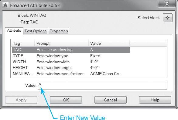
The name of the selected block along with the current attribute tag is displayed at the top left of the dialog box. The Select block button on the right temporarily closes the dialog box so you can select another block to update.
The Attribute tab is the default tab shown in Figure 16-24 that allows you to update attribute values. All the block’s attribute tags and their corresponding prompts and values are displayed in a tabulated list that you can navigate by selecting an attribute with your mouse or by pressing <Enter> while the Value: text box below is selected.
Note
If you modify a block and then select another block before saving the changes, you are prompted to save the changes first. To save changes and update the selected block, select the Apply button at the bottom of the dialog box.
The Value: text box displays the current value assigned to the attribute highlighted in the list box above. Enter a new value and press <Enter> to update the attribute and proceed to the next attribute in the list.
Tip
You can insert a field in a value by right-clicking and selecting Insert Field... on the shortcut menu to display the Field dialog box.
If a multiline attribute is selected, the [...] button is displayed to the right of the Value: text box so you can select it to display the stripped-down multiline text editor and edit multiline attribute values.
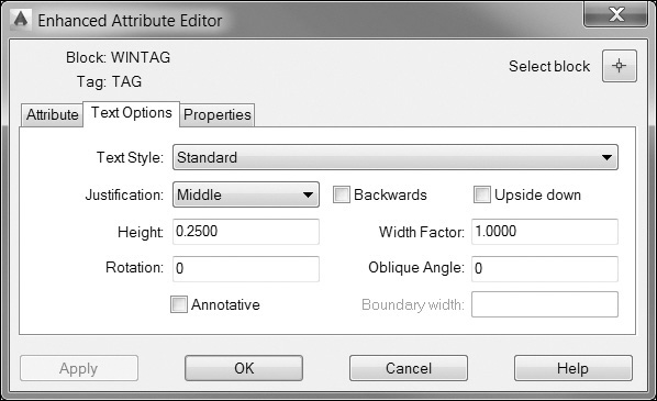
The Text Options tab shown in Figure 16-25 allows you to control the text properties of the currently selected attribute:
• Text Style Allows you to assign a text style from a list of text styles defined in the current drawing
• Justification Allows you to set the attribute justification from a list of standard single-line text justification options
• Height Allows you to specify the height of the attribute text. You can enter a height value via the keyboard or select the Height button to define the height by picking points with your mouse. The Height option is disabled if a text style with a height greater than 0.0 is selected or if the justification is set to Align
• Rotation Allows you to specify the rotation angle of the attribute text. You can enter a value via the keyboard or select the Rotation button to define the rotation angle by picking points with your mouse. The Rotation option is disabled if the justification is set to Align or Fit
• Backwards Specifies whether the attribute text is displayed backward
• Upside down Specifies whether the attribute text is displayed upside down
• Width Factor Sets the character spacing for the attribute text. Entering a value less than 1.0 condenses the text. Entering a value greater than 1.0 expands it
• Oblique Angle Specifies the angle that the attribute text is slanted
• Annotative Specifies whether annotation scaling is on or off
Note
If the current drawing uses color-dependent plot styles, the Plot style list is disabled.
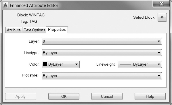
The Properties tab shown in Figure 16-26 allows you to control the general object properties of the currently selected attribute:
• Layer Specifies the attribute layer
• Linetype Specifies the attribute linetype
• Color Specifies the attribute color
• Lineweight Specifies the attribute lineweight
• Plot style Specifies the attribute plot style
When you are done making changes or updates, you can either select OK to exit the dialog box and update the block, or you can select Apply to update the block and keep the Enhanced Attribute Editor dialog box open so you can make more changes.
Edit Attributes Multiple |
|
Ribbon & Panel: |
Insert | Block
|
Menu: |
Modify | Object | Attribute | Global |
Command Line: |
-ATTEDIT |
Command Alias: |
-ATE |

Editing Attributes Globally
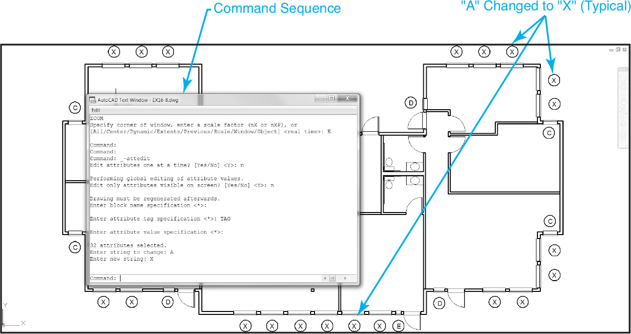
The -ATTEDIT command allows you to quickly update attribute values globally throughout an entire drawing at the same time.
The -ATTEDIT command is rather archaic. In fact, the -ATTEDIT command is actually just the old command line version of the ATTEDIT dialog box–driven command. It may be an old, clunky command, but it is the only way to update more than one attribute at a time in a drawing so that you don’t have to select and update each block individually.
After starting the -ATTEDIT command, AutoCAD prompts: Edit attributes one at a time? ![]() . Enter N or No <Enter> to update attributes globally. AutoCAD then prompts: Edit only attributes visible on screen?
. Enter N or No <Enter> to update attributes globally. AutoCAD then prompts: Edit only attributes visible on screen? ![]() Typically, you should enter No <Enter> to ensure all attributes in the drawing are updated accordingly and not just those shown in the drawing window.
Typically, you should enter No <Enter> to ensure all attributes in the drawing are updated accordingly and not just those shown in the drawing window.
AutoCAD then prompts you for the block name, attribute tag, and attribute value to be found. The default asterisk (*) value represents a wildcard, meaning that all blocks that match that category will be processed. If you know the block name, attribute tag, or attribute value for the block you want to update, you can enter the information to limit the number of blocks that are processed. Pressing <Enter> in response to all these prompts forces AutoCAD to process all the attributed blocks in the drawing.
AutoCAD then requests the original value of the attribute text value to change by prompting Enter string to change: so you can enter the current attribute value. You are then prompted for a new attribute value Enter new string: so you can enter a new value. Immediately after you press <Enter>, AutoCAD searches the drawing for all the attributes with a value of the text to change and updates the attribute with the new value as shown in Figure 16-27.
Managing Attributes
The BATTMAN command allows you to update one or more block attribute definitions via the Block Attribute Manager dialog box so that you can do the following:
• Edit attribute definitions so that you can change the tag, prompt, default, and even the modes (invisible, constant, verify, preset)
Ribbon & Panel: |
Insert | Block
|
Menu: |
Modify | Object | Attribute | Block Attribute Manager |
Command Line: |
BATTMAN |
Command Alias: |
None |

• Control attribute definition text options (text style, height, etc.)
• Manage attribute definition object properties (layer, color, linetype, etc.)
• Change the attribute prompt order
• Remove attribute definitions
Changes made with the Block Attribute Manager update the block definition so that all future block insertions reflect the changes. It is also possible to synchronize the changes with blocks that have already been inserted.
Starting the BATTMAN command displays the Block Attribute Manager dialog box shown in Figure 16-28.
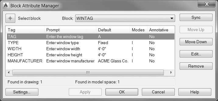
The Select block button allows you to choose a block definition to edit by selecting a corresponding block reference in the current drawing. Selecting the Select block button temporarily closes the Block Attribute Manager dialog box and prompts you to Select a block:. Select the block to update, and the dialog box is redisplayed.
Note
If you modify a block and then select another block before saving the changes, you are prompted to save the changes first. To save changes and update the selected block, select the Apply button at the bottom of the dialog box.
The Block: list box allows you to select the block from the list of blocks currently defined in the drawing.
The tag, prompt, default, mode, and annotative properties of all the attributes defined for the selected block are displayed in the list box in the middle of the dialog box. The number of block references found in the drawing and whether they are located in the current layout are displayed directly below the list box.
The Settings... button at the bottom of the dialog box allows you to control what information is displayed in the attribute list box. Selecting the Settings... button displays the Block Attribute Settings dialog box shown in Figure 16-29.
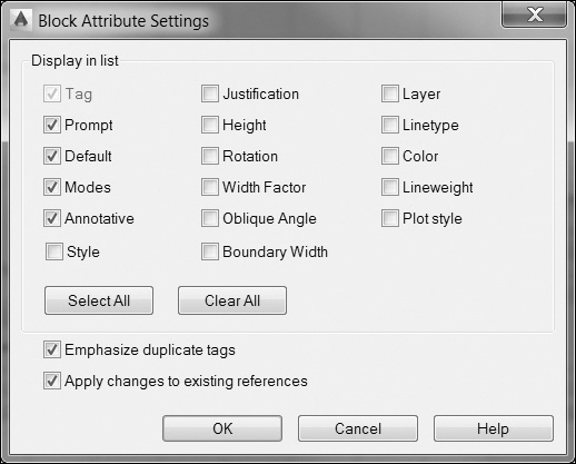
The following options are available:
• The Display in list area is where you select which properties you want to display in the attribute list. Selected properties are displayed as an additional column in the list. The Tag property is always displayed.
• The Select All button selects all of the properties in the Display in list area above.
• The Clear All button clears all of the properties in the Display in list area above.
• The Emphasize duplicate tags check box turns duplicate tag emphasis on and off. When the Emphasize duplicate tags check box is selected, duplicate tag names are changed to red in the attribute list in the Block Attribute Manager dialog box so they can be easily identified.
• The Apply changes to existing references check box indicates whether to update all the existing block references in the drawing when any changes are made. When the Apply changes to existing references check box is selected, all existing and new block references are updated with the new attribute definitions. If it is not selected, only new block references have the new attribute definitions.
• The OK button accepts any setting changes, closes the Block Attribute Settings dialog box, and returns you to the Block Attribute Manager so you can continue to make any changes.
In the Block Attribute Manager dialog box, there are several more options:
• The Sync button updates all block references in the drawing with the currently defined attribute properties. Attribute values are not affected by any changes.
• The Move Up button moves the selected attribute tag up in the prompt order.
• The Move Down button moves the selected attribute tag down in the prompt order.
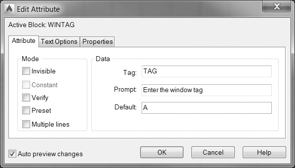
• The Edit... button displays the Edit Attribute dialog box shown in Figure 16-30.
Note
The Move Up and Move Down buttons are both disabled when a constant attribute is selected.
Using the Edit Attribute dialog box, you can modify the attribute definition properties. The name of the selected block is displayed at the top left of the dialog box. The Attribute tab is the default tab shown in Figure 16-30 that allows you to update attribute definitions; you can control:
• The Mode area is where you update the visibility and other attribute options that are set when you insert the block. There are five different options:
• Invisible Specifies that attribute values are not displayed or printed when you insert the block
• Constant Makes attribute a constant value so that it cannot be updated either when it is inserted or anytime later. This option is disabled when using the Block Attribute Manager. The Constant option can be used only when an attribute is first defined
• Verify Has you verify that the attribute value is correct when you insert the block by prompting you for the attribute information twice
• Preset Sets the attribute to its default value and does not prompt you for the attribute information although it is possible to still update the attribute after it is inserted using the techniques explained in the following section
• Multiple lines Allows you to use multiline attributes
• The Data area is where you update the attribute tag, prompt, and default value:
• Tag The unique alphanumeric key used to identify the attribute. Enter a descriptive name using any combination of characters except spaces. Lowercase letters are automatically changed to uppercase. Attribute tags can be up to 256 characters long
• Prompt The prompt that is displayed either in the Edit Attribute dialog box or at the command prompt when you insert the block. If the prompt field is left blank, the attribute tag is used as a prompt. The Prompt option is disabled if you are defining an attribute with the Constant mode selected
• Default Specifies the default attribute value used
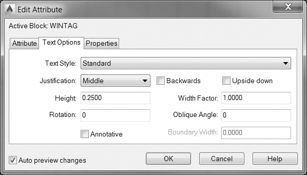
The Text Options tab shown in Figure 16-31 allows you to control the text properties of the currently selected attribute definition:
• Text Style Allows you to assign a text style from a list of text styles defined in the current drawing
• Justification Allows you to set the attribute justification from a list of standard single-line text justification options
• Height Allows you to specify the height of the attribute text. The Height option is disabled if a text style with a height greater than 0.0 is selected or if the justification is set to Align
• Rotation Allows you to specify the rotation angle of the attribute text. The Rotation option is disabled if the justification is set to Align or Fit
• Backwards Specifies whether the attribute text is displayed backward
• Upside down Specifies whether the attribute text is displayed upside down
• Width Factor Sets the character spacing for the attribute text. Entering a value less than 1.0 condenses the text. Entering a value greater than 1.0 expands it
• Oblique Angle Specifies the angle that the attribute text is slanted
• Annotative Specifies whether the attribute scales up and down using the current annotation scale
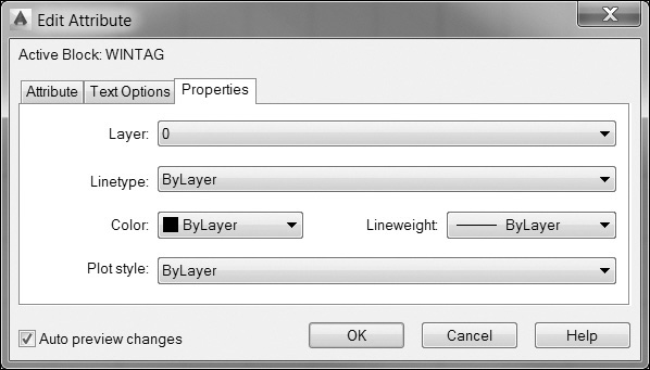
The Properties tab shown in Figure 16-32 allows you to control the general object properties of the currently selected attribute definition:
• Layer Specifies the attribute layer
• Linetype Specifies the attribute linetype
• Color Specifies the attribute color
• Lineweight Specifies the attribute lineweight
• Plot style Specifies the attribute plot style
The Auto preview changes check box allows you to immediately display any updates or changes made in the Edit Attribute dialog box. If the Auto preview changes check box is selected, any changes are immediately displayed.
Note
The Auto preview changes check box is disabled if the Apply changes to existing references check box is not selected in the Block Attribute Settings dialog box described earlier.
The OK button accepts any setting changes, closes the Edit Attribute dialog box, and returns you to the Block Attribute Manager so you can continue to make any changes.
The Remove button removes the selected attribute from the block definition. The Remove button is disabled when a block has only one attribute.
The Apply button applies the changes you made to all block references in the drawing but does not close the Block Attribute Manager.
Select OK to accept any updates and close the Block Attribute Manager dialog box.
Exercise 16-8 Updating and Editing Attributes
![]() Open the building floor plan drawing named EX16-8 in the student data files.
Open the building floor plan drawing named EX16-8 in the student data files.
To access student data files, go to www.pearsondesigncentral.com.
![]() Set layer A-Glaze-Iden current.
Set layer A-Glaze-Iden current.
![]() Start the INSERT command.
Start the INSERT command.
![]() Select the Uniform Scale check box and set the X Scale to 48.
Select the Uniform Scale check box and set the X Scale to 48.
![]() Insert the WINTAG.DWG file created in Exercise 16-7 as a block using the Browse... button.
Insert the WINTAG.DWG file created in Exercise 16-7 as a block using the Browse... button.
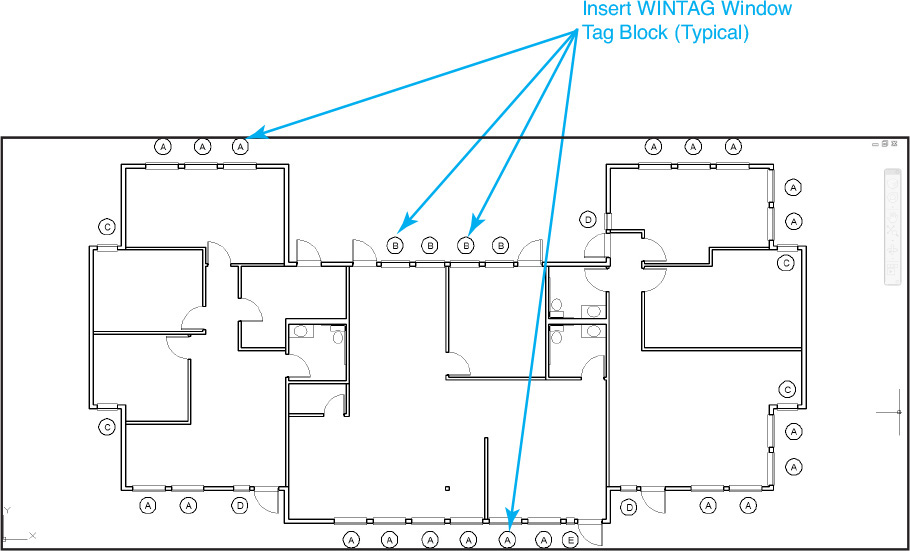
![]() Locate the window tags as shown in Figure 16-33, and update them with the following attribute values:
Locate the window tags as shown in Figure 16-33, and update them with the following attribute values:
![]() Change the window manufacturer from Glassarama, Inc. to SpectorLite for all “D” type window tags in the drawing using either the EATTEDIT or the ATTEDIT command.
Change the window manufacturer from Glassarama, Inc. to SpectorLite for all “D” type window tags in the drawing using either the EATTEDIT or the ATTEDIT command.
![]() Change the attribute text color to blue for the TAG attribute for all blocks in the building plan drawing using the BATTMAN command.
Change the attribute text color to blue for the TAG attribute for all blocks in the building plan drawing using the BATTMAN command.
![]() Save the drawing as CH16_EXERCISE8.
Save the drawing as CH16_EXERCISE8.
Extracting Attributes
It is possible to extract property information from objects in drawings, including blocks and their attributes, to a formatted table in the current drawing or to an external file so that you can quickly create schedules, parts lists, bills of materials, and other tabular-type information based on the current drawing, or even multiple drawings.
Tip
The extracted data can even be merged and linked with information in a Microsoft Excel® spreadsheet so that is possible to include additional external information.
To make the extraction process as easy as possible, AutoCAD provides the Data Extraction wizard, which guides you through a series of preprogrammed steps so that you can provide the following information.
Extract Data |
|
Ribbon & Panel: |
Insert | Linking & Extraction
|
Menu: |
Tools | Data Extraction... |
Command Line: |
DATA-EXTRACTION |
Command Alias: |
DX |

• Data source for information to extract
• Current drawing
• Multiple drawings or sheet set
• Selected objects
• The block names and attribute tags to extract
• Whether to output the attribute information to an AutoCAD table or to output the information to one of the following external file types:
• Comma-delimited text file (CSV)
• Microsoft Excel® spreadsheet (XLS)
• Microsoft Access® database (MDB)
• Generic text file (TXT)
The Data Extraction wizard saves all the settings you specify in each step to an external file (DXE) so that you can use it the next time you use the Data Extraction wizard.
Extracting Attribute Data
The DATAEXTRACTION command starts the Data Extraction wizard to guide you through the steps to extract attribute information.
Starting the DATAEXTRACTION command displays the Data Extraction wizard on the Begin page as shown in Figure 16-34.
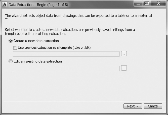
The Begin page allows you to select whether you want to specify new extraction settings from scratch or use settings previously saved in an attribute extraction file (DXE or BLK).
If you select the Use previous extraction as a template option, you must select the [...] button on the right to select a file using the standard file selection dialog box.
Note
If you are creating a new data extraction, you must create a data extraction template file (DXE) before proceeding to the Define Data Source page.
The Edit an existing data extraction option allows you to modify an existing data extraction (DXE) file. You must select the [...] button on the right to select a file using the standard file selection dialog box.
Select the Next > button on the bottom to proceed to the Define Data Source page shown in Figure 16-35 or the Cancel button to close the wizard.
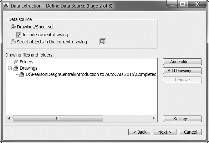
The Define Data Source page allows you to select one of the following data sources from which to extract the attribute information:
• Drawings/Sheet set Enables the Add Folder... and Add Drawings... buttons so you can add a folder or more drawings (DWG) or sheet sets (DST) using the standard file selection dialog box. The current drawing is included by default
• Select objects in the current drawing Enables the Select objects button so you can select one or more blocks in the current drawing
Note
You can delete one or more files from the list by selecting the file(s) and selecting the Remove button on the right.
The Drawing files and folders: list box lists all the drawing files or sheets in the selected sheet set from which attributes will be extracted.
The Settings... button displays the Data Extraction—Additional Settings dialog box shown in Figure 16-36.
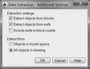
The Additional Settings dialog box allows you specify whether to include nested blocks and xrefs, as well as specify which types of blocks should be included in the overall block count.
The Extraction settings area allows you to control which blocks are included in the attribute extraction process and whether to include xrefs in the block count.
• Extract objects from blocks Includes blocks nested within other blocks
• Extract objects from xrefs Includes blocks located in any attached xrefs
• Include xrefs in block counts Includes attached xrefs as blocks in block counts
The Extract from area provides options for which objects to include in the extraction process.
• Objects in model space Extracts from only block references in model space and ignores any blocks located in paper space layouts
• All objects in drawing Extracts from all block references in the entire drawing (model space and paper space)
The OK button accepts any setting changes, closes the Additional Settings dialog box, and returns you to the Data Extraction wizard so you can continue to the next step.
Select the Next > button on the bottom to proceed to the Select Objects page shown in Figure 16-37, the Cancel button to close the wizard, or the <Back button to return to the previous page.
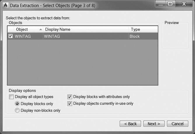
The Select Objects page allows you to select the objects and drawing information to be extracted. Just about any AutoCAD object information can be extracted including blocks and non-blocks.
Tip
It is possible to resize columns with your mouse and reverse the sort order by clicking on the column header. You can also select or unselect all objects via a right-click shortcut menu.
The Objects list displays each object by its name in the Object column. Blocks are listed by block name, and non-blocks are listed by their object name.
The Display Name column allows you to enter an optional alternative name for an object as it will appear in the extracted information. To change a display name, right-click in the Display Name column and select Edit Display Name from the shortcut menu.
The Type column indicates whether the object is a block or non-block.
The Preview area displays a preview image of the checked block in the Objects list.
You can limit the types of objects displayed in the Objects list in the Display options area at the bottom.
The Display all object types option displays a list of all object types (blocks and non-blocks) in the Objects list. It is on by default.
Turning off the Display all object types option allows you to toggle between the Display blocks only option and the Display non-blocks only option so you can further filter the Objects list.
The Display blocks with attributes only option displays only those blocks that have attributes in the Objects list.
The Display objects currently in-use only will limit the Objects list to objects that exist in the selected drawings.
Select the Next > button at the bottom to proceed to the Select Properties page shown in Figure 16-38, the Cancel button to close the wizard, or the <Back button to return to the previous page.
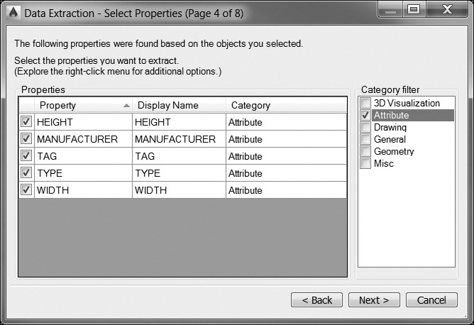
The Select Properties page allows you to control the object, block, and drawing properties to extract.
Each row in the Properties list displays a property name, display name, and category.
Tip
It is possible to resize columns with your mouse and reverse the sort order by clicking on the column header. You can also select or unselect all properties via a right-click shortcut menu.
The Property column displays the properties of all the objects selected on the Select Objects page in the previous step. These are the same object properties displayed in the Properties palette in AutoCAD.
The Display Name column allows you to enter an optional alternative name for a property as it will appear in the extracted information. To change a display name, right-click in the Display Name column and select Edit Display Name from the shortcut menu.
The Category column displays a category for each property. For example, General designates ordinary object properties, such as color or layer. Attribute designates user-defined attributes. These are the same object categories displayed in the Properties palette in AutoCAD.
The Category filter check box list allows you to filter the list of properties shown in the Properties list based on the category listed in the Category column. Only checked categories are displayed.
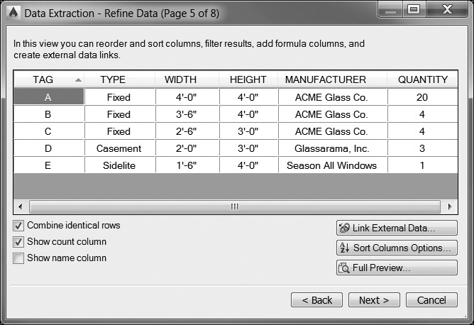
Select the Next > button on the bottom to proceed to the Refine Data page shown in Figure 16-39, the Cancel button to close the wizard, or the <Back button to return to the previous page.
Note
Special icons are displayed in the column header for inserted formula columns and columns extracted from a Microsoft Excel spreadsheet.
The Refine Data page allows you to modify the structure of the data extraction table. You can reorder and sort columns, filter results, add formula columns and footer rows, and even create a link to data in a Microsoft Excel spreadsheet.
The grid in the middle of the dialog box displays properties that were selected in the Select Properties page in the previous step in a tabular format. The Quantity and Name columns display by default and can be turned off as explained below.
The Combine identical rows check box groups identical records by row in the table and updates the Quantity column with the sum total.
The Show count column check box toggles the Quantity column on and off in the table display.
The Show name column check box toggles the Name column on and off in the table display.
The Link External Data... button displays the Link External Data dialog box, where you can create a link between the extracted drawing data and data in an Excel spreadsheet.
The Sort Columns Options... button displays the Sort Columns dialog box, where you can sort data across multiple columns.
The Full Preview... button displays a full preview of the final output, including linked external data. The preview is for viewing only.
Right-clicking in a column displays the shortcut menu shown in Figure 16-40, which gives you the following options:
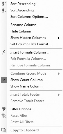
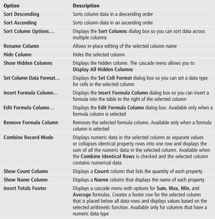
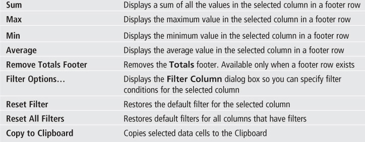
Select the Next > button at the bottom to proceed to the Choose Output page shown in Figure 16-41, the Cancel button to close the wizard, or the <Back button to return to the previous page.
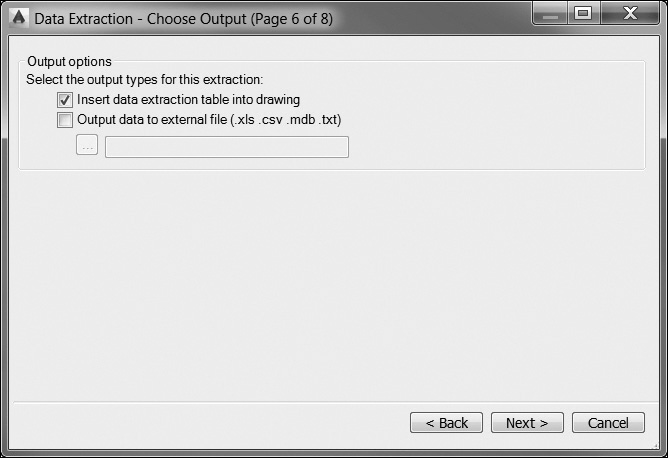
The Choose Output page allows you to select the type of output to which the data are extracted.
The Insert data extraction table into drawing check box allows you to extract the attribute information to an AutoCAD table.
The Output data to external file check box allows you to export the attribute information to the file type and location you specify. Selecting the [...] button displays the standard Save As file dialog box so you can select the file type via the File of type: list box at the bottom of the dialog box and the folder location to save the file. By default, the file name is the same name as the current drawing file. The three-character file extension is determined by the file type selected. The four file output options are as follows:
• XLS Microsoft Excel spreadsheet
• MDB Microsoft Access database
• CSV Comma-separated file format
• TXT Tab-separated file format
Select the Next > button at the bottom to proceed to either the Table Style page shown in Figure 16-42 or the Finish page shown in Figure 16-43, the Cancel button to close the wizard, or the <Back button to return to the previous page.
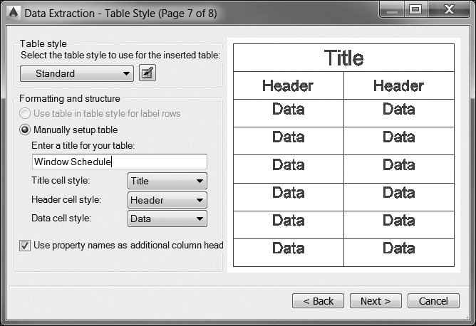
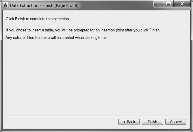
The Table Style page allows you to control the appearance of the table before it is inserted in the drawing.
Note
The Table Style step is displayed only if the Insert data extraction table into drawing check box was selected previously on the Choose Output page.
The Table style area at the top allows you to control the table style used for the extracted data. The Select the table style to use for the inserted table list box allows you to select an existing table style. You can also select the Table Style button to the right to display the Table Style dialog box to modify an existing table style or create a new one.
The Formatting and structure area allows you to fine-tune the final table structure and format.
The Use table in table style for label rows option creates the data extraction table with a set of top rows that contain label cells and a bottom set of label rows that contain header and footer cells. Extracted data are inserted between the top and bottom label rows.
The Manually setup table option allows you to manually enter a title and select a specific title, header, and data cell style.
The Enter a title for your table: text box allows you to enter a title for the table. This row is not overwritten when the table is updated. If the selected table style does not include a title row, this option is not available. The default table style, Standard, includes a title row.
The Title cell style: list allows you to select a separate style for the title cell. Select the drop-down list to select a title cell style defined in the selected table style.
The Header cell style: list allows you to select a separate style for the header row. Select the drop-down list to select a cell style defined in the selected table style.
The Data cell style: list allows you to select a separate style for data cells. Select the drop-down list to select a cell style defined in the selected table style.
The Use property names as additional column headers check box includes column headers and uses the Display Name property as the header row.
For More Details
See page 478 in Chapter 12 for more details about controlling table format using table styles.
Select the Next > button at the bottom to proceed to the Finish page shown in Figure 16-43, the Cancel button to close the wizard, or the <Back button to return to the previous page.
The Finish page allows you to complete the process of extracting object property data that was specified in the wizard and creates the output type that was specified on the Choose Output page.
Note
If data linking and column matching to an Excel spreadsheet was defined in the Link External Data dialog box, the selected data in the spreadsheet are also extracted.
If you select the Insert data extraction table into drawing check box on the Choose Output page, when you select the Finish button, a table will be attached to your mouse cursor. AutoCAD then prompts you to Specify insertion point: so you can locate the table as shown in Figure 16-44.
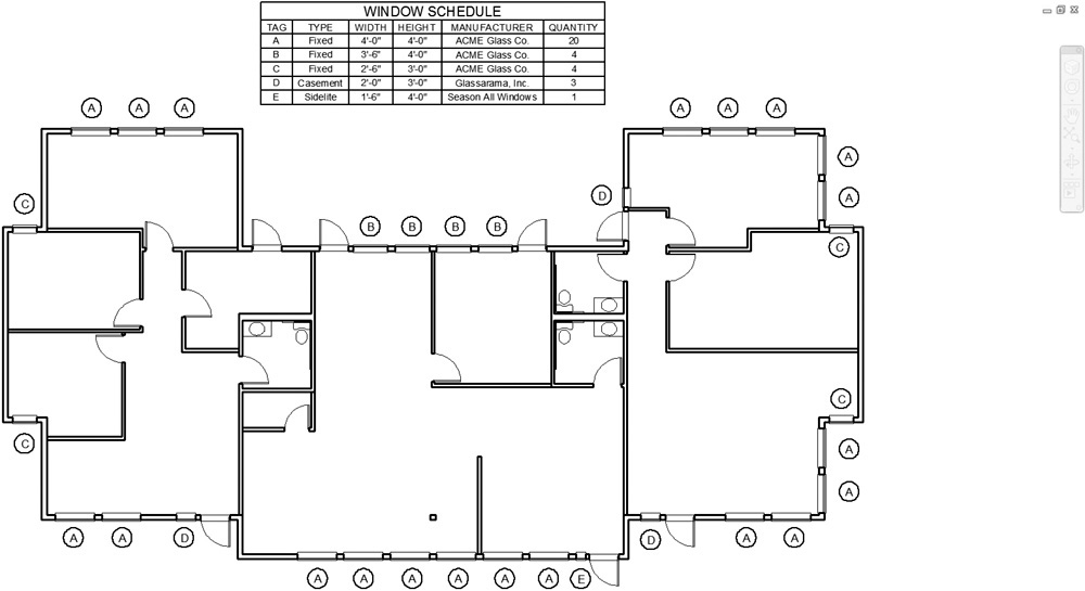
If the Output data to external file option was selected, the extracted data are saved to the specified file type.
Updating Data Extraction Table Data Manually
Data extraction table data are locked by default to prevent the data from being updated and possibly getting out of sync with the source data (attributes). When you click on a table cell, a Lock icon is displayed along with the data extraction information as shown in Figure 16-45.
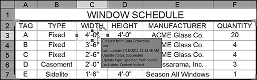
You can unlock a cell by selecting Locking from the right-click menu and checking the Unlocked cascade menu item. Table data that are overwritten manually will be updated when the table data are updated using the automated update data links options explained in the following section.
Updating Data Extraction Table Data Automatically
You can update data extraction table data automatically when the extracted source data (attributes) change.
AutoCAD locates a Data Link icon in the status tray on the far right of the status bar any time a data extraction table is located in your drawing. You can right-click on the icon and select Update All Data Links... from the shortcut menu shown in Figure 16-46, and AutoCAD will read all the attributes in the drawing and update the table data with any changes.
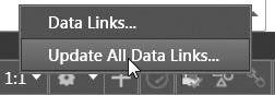
Note
You can also update links from the Tools menu on the Data Links cascade menu.
You can select to be notified when extracted data have changed. When information in the data source has changed that affects the extracted data in a table, the Data Extraction—Outdated Table dialog box is displayed so that you can update the table data automatically (see Figure 16-47).
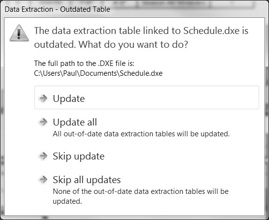
Notification is controlled by the current DXEVAL system variable setting. By default, DXEVAL is set to check whether the extracted data are not current only when the PLOT or PUBLISH command is used. It can also be set to occur with the OPEN, SAVE, and ETRANSMIT commands. The DXEVAL system is stored as an integer using the sum of the following values:
• 0 No notification
• 1 Open
• 2 Save
• 4 Plot
• 8 Publish
• 16 eTransmit/Archive
• 32 Save with Automatic Update
• 64 Plot with Automatic Update
• 128 Publish with Automatic Update
• 256 eTransmit/Archive with Automatic Update
The default value of DXEVAL is 12, which enables notification for the PLOT and PUBLISH commands.
Exercise 16-9 Extracting Attributes
![]() Continue from Exercise 16-8.
Continue from Exercise 16-8.
![]() Use the Data Extraction wizard and extract all the block attributes to create the window schedule shown in Figure 16-44 using the AutoCAD table option.
Use the Data Extraction wizard and extract all the block attributes to create the window schedule shown in Figure 16-44 using the AutoCAD table option.
Hint: Use your mouse to reorder and sort the columns as needed in the Refine Data page shown in Figure 16-39. The table must be scaled by a drawing scale factor of 48 after the table is inserted if it is inserted in model space.
![]() Save the drawing.
Save the drawing.
Redefining Blocks
One of the greatest benefits of using blocks in your drawings is that it makes it possible to quickly redefine a block so that all existing and future block references are automatically updated in the drawing to match the new block definition. You may have hundreds, or even thousands, of references of a block in a drawing, and they will all be updated. Think how much time it would take to update each one manually, and it’s easy to appreciate why it is such a great feature.
Updating Blocks Created in the Current Drawing
To redefine a block in the current drawing, you simply follow the steps outlined earlier in the chapter to create the updated block information. You then use the BLOCK command to save the drawing information with the same block name as the existing block name to update by selecting it from the Name: list box at the top of the Block Definition dialog box, as shown in Figure 16-48.
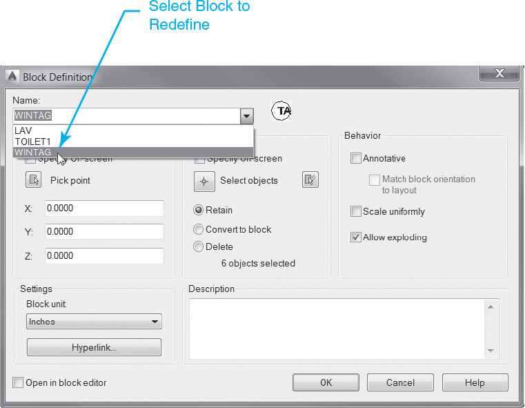
When you select OK to update the block information, AutoCAD displays a message like the one shown in Figure 16-49. This informs you that the block definition already exists and asks you whether you want to update it.
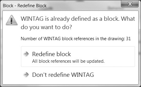
Selecting the Redefine block button replaces the existing block definition with the new one, and all the existing block references in the drawing are immediately updated to reflect the new definition. All future block insertions will also refer to the new block definition.
The easiest way to update a block is to insert the original block and explode it so that you can update its subobjects and then redefine it using the BLOCK command as explained above.
Tip
Be sure that when you insert the original block that you specify a base point that you can remember, a uniform scale of 1.0, and a rotation angle of 0.0. If the base point, scale, or rotation angle is different from the original when you redefine the block, all block references will be updated to reflect the change, causing unpredictable results.
Updating Blocks Inserted from an External Drawing File
Block definitions created by inserting an external drawing file are not automatically updated when the original drawing file is modified. The easiest way to update a block definition created by inserting a drawing file is to simply reinsert the updated drawing file using the INSERT command explained earlier to display the Insert dialog box shown in Figure 16-7 and select the Browse... button to select the updated drawing file using the standard Select Drawing File dialog box.
Edit Reference |
|
Ribbon & Panel: |
Insert | Reference
|
Menu: |
Tools | Xref and In-place Block Editing | Edit Reference In-Place |
Command Line: |
REFEDIT |
Command Alias: |
None |

When you select OK to exit the Insert dialog box and insert the updated block, AutoCAD displays a message like the one shown in Figure 16-49. This informs you that the block definition already exists and asks whether you want to update it. Rather than insert another block reference by picking a point in the drawing, you can press the <Esc> key to cancel the insertion process. All the existing block references are still updated, but you don’t end up with a new, unwanted block reference in your drawing.
Editing Blocks In-Place
The REFEDIT command, which was originally created to edit xrefs, can be used to quickly redefine a block “in-place” without having to explode the block and re-create it using the BLOCK command as explained above.
After starting the REFEDIT command, AutoCAD prompts you to Select reference:. Select the block to redefine, and press <Enter> to display the Reference Edit dialog box shown in Figure 16-50.
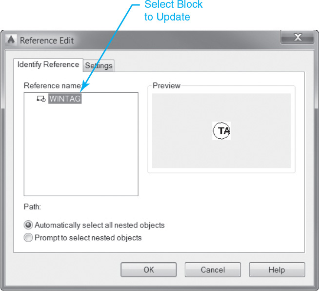
This dialog box provides the following options:
• The Identify Reference tab is used to identify and select the block definition you want to edit.
• The block name is listed on the left in the Reference name: box along with any blocks that might be nested within the block. If multiple blocks are displayed, you must select the block you want to modify from the list. Only one block can be edited in place at a time.
• The Preview window displays a preview image of the currently selected block.
• The Automatically select all nested objects option controls whether nested blocks are included automatically in the block editing session.
• The Prompt to select nested objects option controls whether nested blocks must be selected individually in the block editing session.
• The Settings tab is used to control various block editing settings.
• The Create unique layer, style, and block names check box allows you to control how xref layers and other named objects are managed.
• The Display attribute definitions for editing check box allows you to control whether all the attribute definitions in a block reference are displayed during the block editing session.
Note
When Display attribute definitions for editing is selected, attribute values are turned off, and all the block attribute definitions are displayed so that they can be edited. The updated attribute definitions affect only future block insertions—the attributes in existing block references are unchanged. Attributes defined as Constant cannot be updated.
Additionally, the Lock objects not in working set check box allows you to lock all objects not in the working set so that you don’t inadvertently modify other objects in the drawing while in a block editing session. Locked objects behave similarly to objects on a locked layer—they can be viewed, but they cannot be selected.
working set: The group of objects selected for in-place editing using the REFEDIT command.
Selecting OK puts you in the block editing mode where all the objects that are not part of the working set are locked and faded back so that the objects to edit in the working set stand out as shown in Figure 16-51.
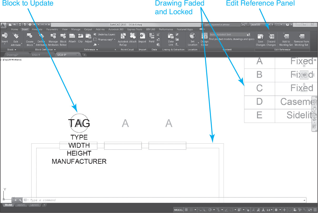
When you are in block editing mode, the Edit Reference panel shown in Figure 16-52 is turned on to allow you to manage the working set and save or discard any changes made to the block definition.
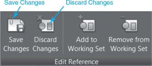
In block editing mode, you can edit the block definition using any of the standard AutoCAD drawing and editing commands. You can add information, erase information, and change object properties—almost anything you would normally do in the AutoCAD drawing editor.
When you are done updating the block definition, select the Save Changes button on the left side of the Edit Reference panel shown in Figure 16-52 to save the changes and exit block editing mode. You can discard any changes and exit block editing mode by selecting the Discard Changes button shown in Figure 16-52.
Redefining Blocks with Attributes
It is possible to redefine block attributes using any of the standard techniques explained so far, but there are a few idiosyncrasies to be aware of. For the most part, only future block references will reflect the changes made to the attribute definition properties and modes—existing block references do not get updated.
Adding new attribute definitions is even more problematic—adding a new attribute to a block affects only future block insertions. Not even the BATTMAN command described earlier allows you to add new attributes. Fortunately, AutoCAD provides the ATTREDEF command to solve the issues surrounding updating blocks with attributes.
Note
When an attribute definition is updated, the current attribute value remains the same; only the attribute properties are updated.
The ATTREDEF Command
The ATTREDEF command redefines the specified block and its attribute definitions by prompting you to select the objects that will make up the block, similar to when you created the block originally. Because of this, the easiest process is to explode the block to make any changes and/or add any new attribute definitions.
Because the ATTREDEF command is not on any menu or ribbon, you must type it at the command prompt. After starting the ATTREDEF command, AutoCAD prompts you to Enter name of the block you wish to redefine:. You must enter the block name at the keyboard. AutoCAD then prompts you to Select objects: so you can select the objects and attributes that make up the block. After you have selected all the block objects, press the <Enter> key, and AutoCAD prompts you to Specify insertion base point of new Block: so you can select the insertion point. You should select an insertion point in the exact location as the original base point, or any existing block references in the drawing will move.
Exercise 16-10 Redefining Blocks
![]() Continue from Exercise 16-9.
Continue from Exercise 16-9.
![]() Start the REFEDIT command, and select any one of the WINTAG window tag blocks.
Start the REFEDIT command, and select any one of the WINTAG window tag blocks.
![]() Select OK in the Reference Edit dialog box to enter block editing mode.
Select OK in the Reference Edit dialog box to enter block editing mode.
![]() Change the window tag circle to a hexagon as shown in Figure 16-53 by erasing the circle and using the POLYGON command to create the hexagon.
Change the window tag circle to a hexagon as shown in Figure 16-53 by erasing the circle and using the POLYGON command to create the hexagon.
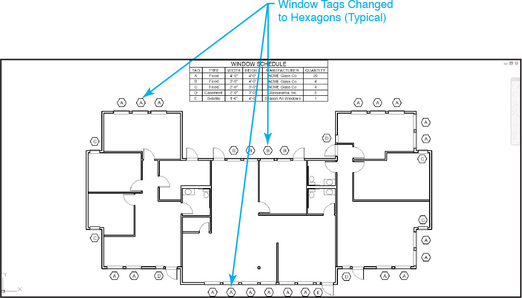
![]() Select the Save Changes button on the Edit Reference panel to save your changes. All window tags in the drawing should immediately change to hexagons.
Select the Save Changes button on the Edit Reference panel to save your changes. All window tags in the drawing should immediately change to hexagons.
![]() Save the drawing.
Save the drawing.
Using DesignCenter to Manage Blocks
AutoCAD’s DesignCenter is a multipurpose tool that provides easy access to blocks, hatch patterns, layers, linetypes, text styles, dimension styles, and other named object information contained in other drawings on your computer, on a network location, or even on the Internet.
DesignCenter allows you to “open” another drawing so that you can view the drawing’s named objects, referred to as drawing content, in list or icon form. You can then copy any of the drawing content from the source drawing to your current drawing by simply dragging and dropping it with your mouse. You can even select multiple objects, making it possible to copy a group of named objects as one. For instance, using this approach, you could copy all the layer definitions from one drawing to another, saving a lot of time. In addition to layers, DesignCenter provides access to the following drawing content:
• Blocks
• Dimension styles
• Layers
• Linetypes
• Table styles
• Text styles
• Xrefs
For the purpose of this chapter, we are going to concentrate on using DesignCenter to manage and insert blocks.
Tip
Using DesignCenter, you can create a standard drawing, or drawings, that contains all of your organization’s standard layers, linetypes, text styles, and so on. Then you can locate it centrally on a network drive, giving your coworkers access to it so all they have to do is drag and drop to set up their drawings.
Designcenter |
|
Ribbon & Panel: |
Insert | Content
|
Menu: |
Tools | Design Center |
Command Line: |
ADCENTER |
Command Alias: |
ADC |

The DesignCenter Window
The ADCENTER command displays the DesignCenter window so that you can locate and insert drawing content from other drawings located on your computer, a network, or the Internet.
Starting the ADCENTER command displays the DesignCenter window shown in Figure 16-54.
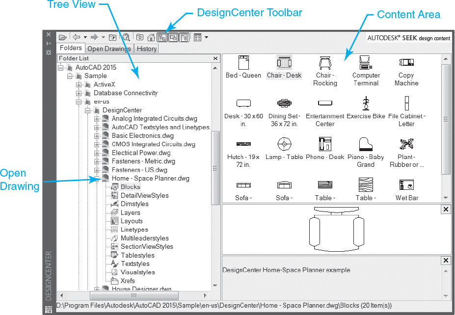
The DesignCenter window consists of three parts:
• Tree view (left pane) Navigation tools used to locate drawing files and Web-based content
• Content area (right pane) Displays the contents of a drawing or Web content once it is located
• Toolbar (top) Additional navigation and display tools
If the tree view is not displayed, select the Tree View Toggle button on the DesignCenter toolbar at the top of the DesignCenter window shown in Figure 16-54.
The following sections explain each of these parts as well as other DesignCenter features.
Tree View
The tree view on the left allows you to locate a drawing file using the following methods so that you can display the drawing’s contents in the content area on the right:
• Folders tab Explorer-like interface that allows you to navigate the hierarchy of files and folders on your computer or attached network drives (see Figure 16-54)
• Open Drawings tab List of all currently open drawings
• History tab History of the last drawings accessed
Tip
You can remove a file from the History tab by selecting the file, right-clicking, and selecting Delete from the shortcut menu.
Content Area
The content area on the right side of the window displays the contents of the drawing or the named object collection currently selected in the tree view on the left. When a block is selected, it is possible to display a preview and a description as shown in Figure 16-55.
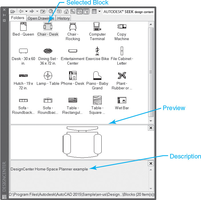
The preview window and description window can be toggled on and off by selecting the Preview and Description buttons on the DesignCenter toolbar shown in Figure 16-57. It is also possible to switch how the information is viewed in the content pane via the Views flyout menu on the right side of the DesignCenter toolbar shown in Figure 16-57 to one of the following standard Explorer-type formats:
• Large icons
• Small icons
• List
• Details
You can navigate in the content area by double-clicking an icon with your mouse to display its contents. You can then select the Up arrow on the DesignCenter toolbar shown in Figure 16-57 to go back up one level in the hierarchy.
Right-clicking on a block icon displays the shortcut menu shown in Figure 16-56 so that you can do the following:
• Insert Block... Displays the Insert dialog box
• Insert and Redefine Inserts the selected block and redefines all block definitions in the drawing
• Redefine only Redefines a block in the drawing but does not insert a copy
• Block Editor Displays the dynamic block editor
• Copy Copies the block to the Windows Clipboard
• Create Tool Palette Creates a custom tool palette
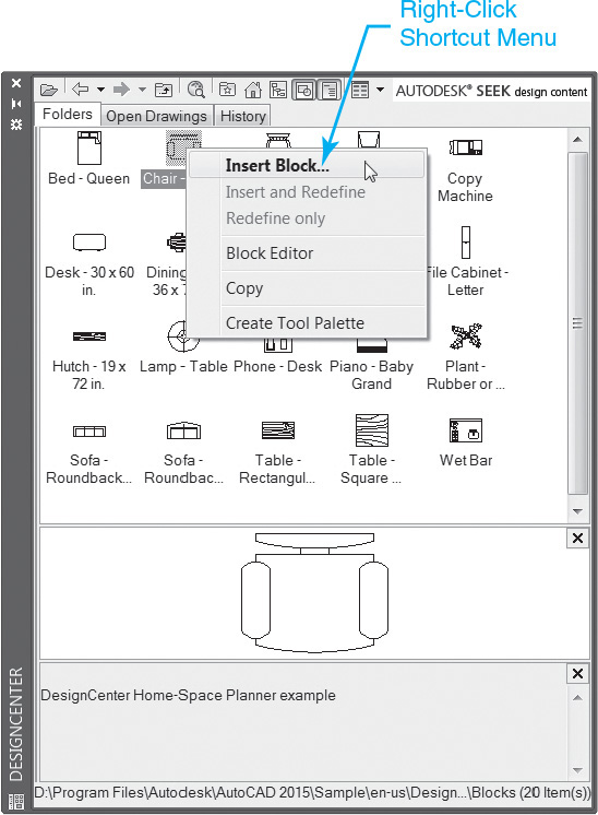
DesignCenter Toolbar
The DesignCenter toolbar shown in Figure 16-57 provides the following navigation tools and display options:
• Load Displays the standard file selection dialog box so you can locate a file and load its information in the content area
• Back Returns to the most recent location in the history list
• Forward Moves forward to a recent location in the history list
• Up Displays the contents of the next level up in the hierarchy
• Search Displays the Search dialog box so you can enter search criteria to locate drawings, blocks, and other named objects within drawings
• Favorites Displays the contents of the Favorites folder in the content area. You can add items to the Favorites folder by right-clicking and selecting Add to Favorites from the shortcut menu
• Home Returns DesignCenter to the home folder. You can change the home folder by navigating to the desired folder in the tree view, right-clicking, and selecting Set as Home from the shortcut menu
• Tree View Toggle Displays and hides the tree view. When the tree view is hidden, you can still navigate in the content area using the techniques described earlier
• Preview Toggle Toggles the preview window on and off in the content area
• Description Toggle Toggles the description window on and off in the content area
• Views Allows you to switch between different display formats in the content area
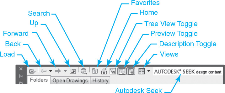
DesignCenter Properties
Just like other AutoCAD windows and palettes, the DesignCenter window can be moved, resized, and docked using your mouse. You can also control these and other features by selecting the Properties button on the window title bar to display the shortcut menu shown in Figure 16-58.
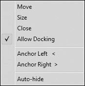
Using the shortcut menu, you can prevent the DesignCenter window from being docked. You can also toggle on and off the Auto-hide feature that collapses the window, so that only the title bar is visible when the mouse pointer is not directly over the window.
Tip
The <Ctrl>+2 keyboard combination can be used to quickly toggle DesignCenter on and off.
Inserting Blocks
Once you locate a block using one of the methods described above and it is visible in the content area, there are three ways you can insert the block into the current drawing using DesignCenter:
• Drag and drop the block into the current drawing using your mouse.
• Double-click on the block in the content area to display the Insert dialog box.
• Right-click on the block in the content area to display the shortcut menu shown earlier in Figure 16-56.
Note
The following exercise requires that you install the sample DesignCenter drawing files that come with AutoCAD 2015. By default, the sample drawings are located in the C:ProgramFilesAutoCAD 2015SampleDesignCenter folder.
Each method has its merits. Dragging and dropping a block is obviously the fastest method, while double-clicking on a block provides the most control because you can specify different block settings in the Insert dialog box. Finally, right-clicking provides the only option to redefine a block. Practice using each method so that you are prepared for any situation.
Autodesk Seek
Autodesk Seek is an online utility that allows you to search product information and drawings from the Web and download them directly into your AutoCAD drawing. It can be accessed either from the right side of the DesignCenter toolbar shown in Figure 16-57 or by entering your search criteria directly on the Content panel on the Insert tab of the ribbon in the Seek design content search box.
Either method will launch your Internet browser and take you to the http://seek.autodesk.com website so you can find the product you are searching for. Once you locate a drawing, you can drag and drop the content into the current AutoCAD drawing.
It is also possible to share your blocks and other content with other Autodesk Seek users by selecting the Share with Autodesk Seek tool on the Autodesk Seek panel on the Output tab of the ribbon. Selecting the Share with Autodesk Seek tool asks you what content you want to share and then takes you through an online submittal process where the selected content is then uploaded to the Autodesk Seek website.
Exercise 16-11 Using DesignCenter
![]() Continue from Exercise 16-10.
Continue from Exercise 16-10.
![]() Set layer A-Furn current.
Set layer A-Furn current.
![]() Start DesignCenter and navigate to the Home-Space Planner.dwg file located in the DesignCenter folder as shown in Figure 16-54.
Start DesignCenter and navigate to the Home-Space Planner.dwg file located in the DesignCenter folder as shown in Figure 16-54.
![]() Select the Blocks icon so you can see the blocks defined in the drawing in the content area on the right as shown in Figure 16-55.
Select the Blocks icon so you can see the blocks defined in the drawing in the content area on the right as shown in Figure 16-55.
![]() Select the Tree View Toggle button on the DesignCenter toolbar shown in Figure 16-57 to turn off the tree view.
Select the Tree View Toggle button on the DesignCenter toolbar shown in Figure 16-57 to turn off the tree view.
![]() Insert blocks using the techniques explained above, and furnish the floor plan in a manner similar to Figure 16-59.
Insert blocks using the techniques explained above, and furnish the floor plan in a manner similar to Figure 16-59.
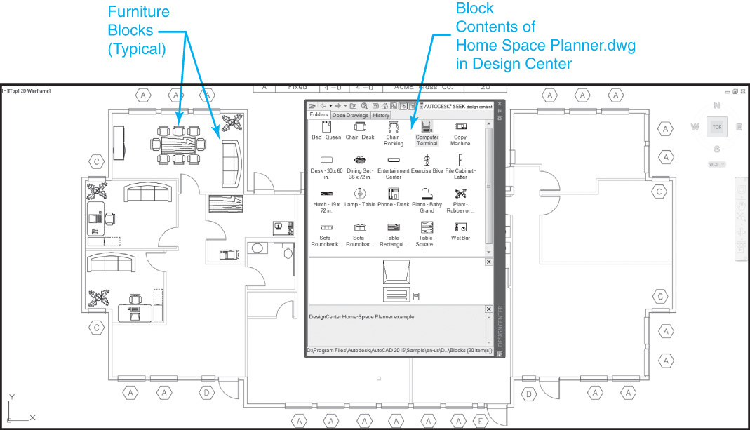
Figure 16-59 Building floor plan with office furniture and equipment blocks inserted using DesignCenter
![]() Save the drawing.
Save the drawing.
Tool Palettes and Dynamic Blocks
Tool palettes are highly customizable palette-type windows that allow you to group and organize blocks, hatch patterns, and even commands, using graphical icons on easily accessible palettes organized in a series of named tabs.
Tool Palettes |
|
Ribbon & Panel: |
View | Palettes
|
Menu: |
Tools | Palettes | Tool Palettes |
Command Line: |
TOOL PALETTES |
Command Alias: |
TP |

Dynamic blocks are multipurpose blocks that can be changed after they are inserted using special grips that allow you to display multiple block views, sizes, block behavior, and more. Using dynamic blocks, one block definition can be used for myriad different scenarios and situations. Dynamic blocks are covered in detail later in this section. The AutoCAD tool palettes are shown in Figure 16-60.
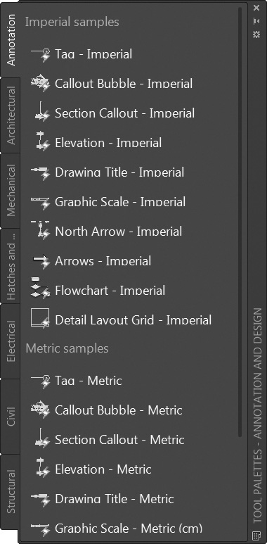
Note
All dynamic blocks have a lightning bolt in the lower right corner of their tool palette icon as shown in Figure 16-60 to indicate that they can be dynamically updated after they are inserted. Inserting and updating dynamic blocks is explained later in this section.
Tool palette tools can be either dragged and dropped directly into your drawing to perform the associated action or selected by clicking on the tool’s icon with your mouse. Figure 16-61 shows the Door-Imperial block being inserted in the drawing by dragging and dropping it from the sample Architectural palette.
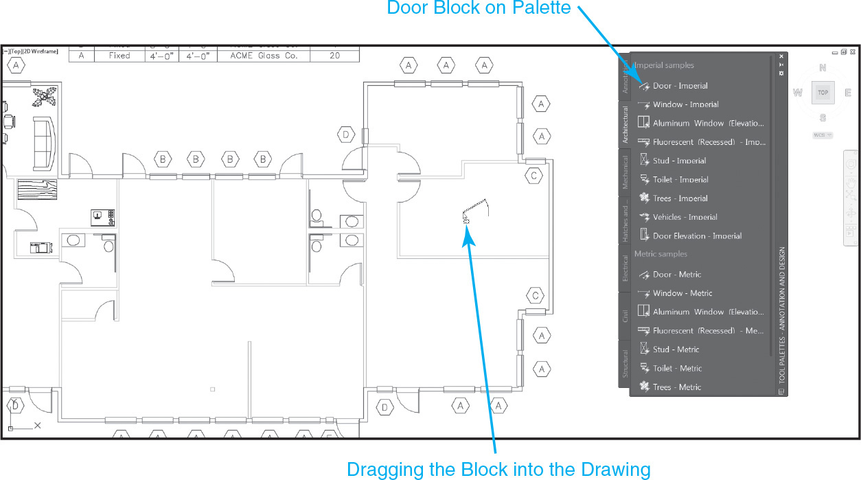
Controlling Tool Palettes
Because they utilize the palette-type window, tool palettes can be hidden when you are not using them via the Auto-hide palette feature, as well as made transparent so that you can see through them to your drawing below using the Transparency palette feature. These and other features can be controlled via the Properties shortcut menu that can be displayed by clicking on the Properties button at the top of the palette title bar (see Figure 16-60).
Tip
The Auto-hide feature can also be quickly turned on and off via the Auto-hide button located directly above the Properties button (see Figure 16-60).
For More Details
See Chapter 1 for more information about controlling different palette properties such as Auto-hide and transparency.
More options are available by right-clicking anywhere on the title bar to display the shortcut menu shown in Figure 16-62.
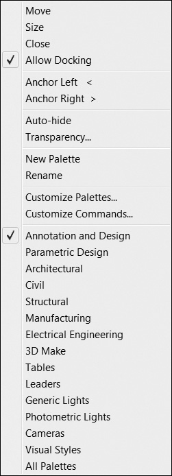
In addition to the Auto-hide and Transparency palette features, the tool palette title bar right-click menu allows you to do the following:
• Turn tool palette docking off so that if you drag a palette to the far left or right side of your screen, the palette will remain in a floating state and not attach itself to the AutoCAD window.
• Anchor tool palettes on the left or right side of the AutoCAD window. Anchored palettes are palettes that are docked but hidden using the Auto-hide feature so that only the title bar is visible. Placing your mouse over the palette title bar displays the entire palette, but it remains anchored.
• Create new empty tool palettes and rename existing tool palettes.
• Turn tool palette groups off and on. Related tool palettes can be grouped together in categories so you can control what palettes are displayed by category.
• Customize tool palette groups. The Customize Palettes... menu item displays the Customize dialog box shown in Figure 16-63 so you can do the following:
• Add/remove/move palettes by dragging palettes with your mouse. A palette can be added to a group by dragging it from the Palettes: list box on the left to the desired palette group on the right.
• Add/remove palette groups by right-clicking on a group in the Palette Groups: list box on the right and using the shortcut menu.
• Export and import tool palettes using the XTP file format so that palettes can be shared with other users by right-clicking on a palette in the Palettes: list box on the left and selecting Export... or Import... from the shortcut menu to display the Windows file dialog box.
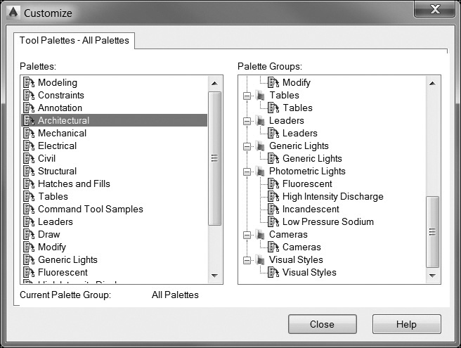
• Add custom commands. The Customize Commands... menu item displays the Customize User Interface dialog box with a list of all the AutoCAD commands. To add a command to a tool palette, you simply drag it from the Command List: and drop it onto the tool palette of your choice.
But wait, there’s more. There is a total of four different tool palette right-click shortcut menus depending on where you right-click with your mouse. If you right-click on a tool palette anywhere between toolbar icons on an empty space on the palette background, the shortcut menu in Figure 16-64 is displayed.
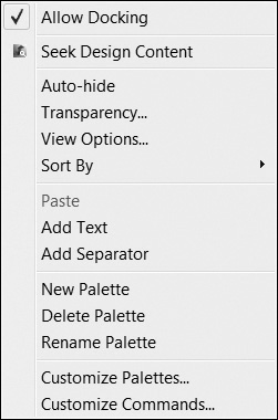
In addition to most of the commands and features already discussed, this menu also allows you to control different display options. The View Options... menu item displays the View Options dialog box so that you can switch between icon and list view, as well as control the size of the images used for the icons. The Sort By cascade menu allows you to automatically sort tool icons by name or type.
Right-clicking on the named tab on a tool palette displays yet another shortcut menu. This menu allows you to move a palette up and down in the palette order, rename a palette, or create a new palette.
Finally, right-clicking directly over a tool palette icon displays a shortcut menu that allows you to cut, copy, delete, rename, and control the selected tool’s properties.
Tool Properties
The Properties... menu item located on the bottom of a tool’s right-click shortcut menu displays the Tool Properties dialog box shown in Figure 16-65 so you can edit the tool’s name and description, as well as control tool-specific properties such as block locations, hatch pattern names, and command macros depending on the tool type selected. The properties for a block are shown in Figure 16-65.
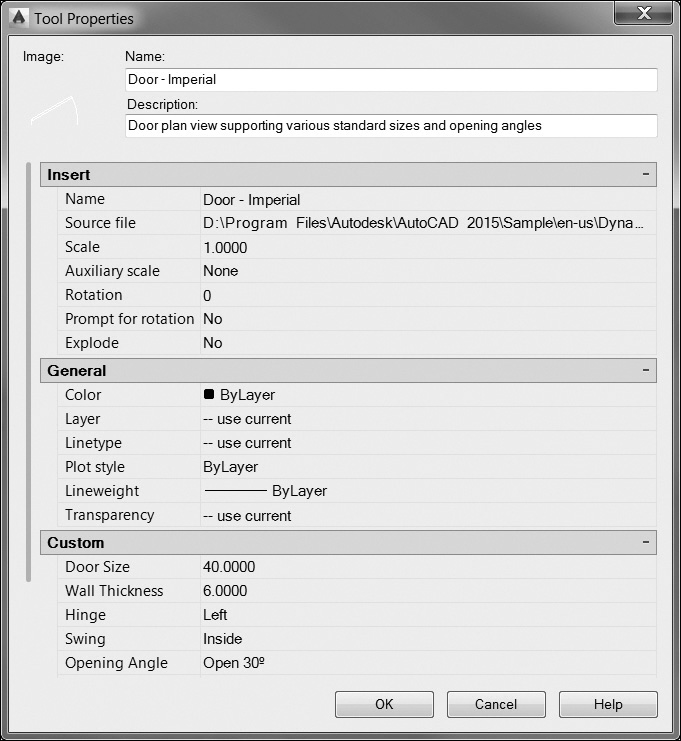
Each tool also has general properties such as layer, color, and linetype that can be controlled via the Tool Properties dialog box (see Figure 16-65). These properties are applied to any object type that is created when the corresponding tool palette icon is selected. For instance, setting a block’s Layer property to any layer setting other than—use current will insert the block on the layer specified.
Tip
It is possible to rearrange the order of the tools on a tool palette by left-clicking a tool icon and dragging it to another location.
Exercise 16-12 Using Tool Palettes
![]() Continue from Exercise 16-11.
Continue from Exercise 16-11.
![]() Turn on tool palettes via the Palettes panel on the View tab of the ribbon.
Turn on tool palettes via the Palettes panel on the View tab of the ribbon.
![]() Right-click anywhere on the Tool Palettes title bar, and select Annotation and Design from the shortcut menu to turn on only the Annotation and Design tool palettes shown in Figure 16-60.
Right-click anywhere on the Tool Palettes title bar, and select Annotation and Design from the shortcut menu to turn on only the Annotation and Design tool palettes shown in Figure 16-60.
![]() Size and position the palettes on the screen using your mouse.
Size and position the palettes on the screen using your mouse.
![]() Turn the Auto-hide feature on by selecting the Auto-hide button at the top of the palette title bar directly above the Properties button.
Turn the Auto-hide feature on by selecting the Auto-hide button at the top of the palette title bar directly above the Properties button.
![]() Move your mouse off the palette so that the palette closes and only the palette title bar is visible.
Move your mouse off the palette so that the palette closes and only the palette title bar is visible.
![]() Right-click anywhere on the Tool Palettes title bar again, and select Anchor Right > to anchor the tool palette on the right side of the screen.
Right-click anywhere on the Tool Palettes title bar again, and select Anchor Right > to anchor the tool palette on the right side of the screen.
![]() Put your cursor over the anchored tool palette to display it, and select the Architectural palette tab to make it active.
Put your cursor over the anchored tool palette to display it, and select the Architectural palette tab to make it active.
![]() Select the Door-Imperial block at the top of the Architectural palette by clicking on it with your left mouse button. AutoCAD should prompt you to Specify insertion point or
Select the Door-Imperial block at the top of the Architectural palette by clicking on it with your left mouse button. AutoCAD should prompt you to Specify insertion point or ![]() .
.
![]() Pick a point to locate the block anywhere on the floor plan.
Pick a point to locate the block anywhere on the floor plan.
![]() Select the Fluorescent (Recessed)-Imperial block, hold your mouse button down, and drag and drop the light fixture block anywhere in the drawing.
Select the Fluorescent (Recessed)-Imperial block, hold your mouse button down, and drag and drop the light fixture block anywhere in the drawing.
![]() Right-click on the Door-Imperial block on the Architectural palette and select Properties... from the shortcut menu to display the Tool Properties dialog box.
Right-click on the Door-Imperial block on the Architectural palette and select Properties... from the shortcut menu to display the Tool Properties dialog box.
![]() Change the Layer property under the General category from —use current to A-DOOR, and select OK to close the dialog box.
Change the Layer property under the General category from —use current to A-DOOR, and select OK to close the dialog box.
![]() Insert another Door-Imperial block. It should now always insert on the A-DOOR layer regardless of what layer is current.
Insert another Door-Imperial block. It should now always insert on the A-DOOR layer regardless of what layer is current.
![]() Save the drawing.
Save the drawing.
Adding Tools to Tool Palettes
One of the coolest things about tool palettes is that you can add information to a palette by simply selecting an object in your drawing and dragging it onto the tool palette where you want it to be located. If the object is a block, it is added to the palette as a block. If the object is a hatch pattern, the hatch pattern is added to the palette. If the object selected is not a block or a hatch pattern, the command used to create the object is added to the palette. For instance, dragging a piece of multiline text from a drawing onto a tool palette will add the MTEXT command using the default multiline text icon as shown in Figure 16-66.
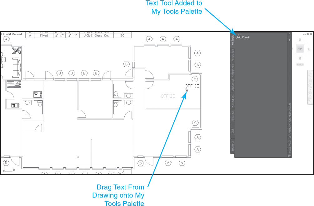
There are a couple of different ways to add blocks to a palette besides dragging them from the drawing.
Using the DesignCenter palette described earlier, it is possible to automatically create a new palette that contains all the blocks in a drawing by right-clicking on a drawing on the DesignCenter Folders tab and selecting the Create Tool Palette menu item from the shortcut menu. A new palette with the same name as the drawing is added to the current palette group with blocks and tool icons generated for each block.
DesignCenter can also create a new palette that consists of all the drawing files located in a folder. If you right-click on a folder that contains drawing (DWG) files and select Create Tool Palette of Blocks from the shortcut menu, AutoCAD will create a new tool palette with the same name as the folder with blocks and icons for each drawing file in the folder.
Tip
Drawing (DWG) files can also be added to a tool palette by dragging and dropping them from Windows Explorer onto the desired palette. It is even possible to add multiple drawings at the same time using the <Ctrl> and <Shift> keys to select multiple files.
Exercise 16-13 Adding Tools to Tool Palettes
![]() Continue from Exercise 16-12.
Continue from Exercise 16-12.
![]() Right-click anywhere on the Tool Palettes title bar, and select New Palette from the shortcut menu to create a new palette. Name the new palette My Tools.
Right-click anywhere on the Tool Palettes title bar, and select New Palette from the shortcut menu to create a new palette. Name the new palette My Tools.
![]() Select any toilet block on the floor plan in the drawing so it is highlighted, and add it to the My Tools palette by dragging and dropping it onto the palette from the drawing. Be careful not to select a grip when dragging it.
Select any toilet block on the floor plan in the drawing so it is highlighted, and add it to the My Tools palette by dragging and dropping it onto the palette from the drawing. Be careful not to select a grip when dragging it.
![]() Select any wall line so it is highlighted, and add it to the My Tools palette by dragging and dropping it onto the palette from the drawing. You should now have a Line tool with a flyout of assorted drawing commands.
Select any wall line so it is highlighted, and add it to the My Tools palette by dragging and dropping it onto the palette from the drawing. You should now have a Line tool with a flyout of assorted drawing commands.
![]() Select the Line tool, and create a line.
Select the Line tool, and create a line.
![]() Right-click on the My Tools tab, and select Move Up from the shortcut menu to move the My Tools palette up in the palette order.
Right-click on the My Tools tab, and select Move Up from the shortcut menu to move the My Tools palette up in the palette order.
![]() Repeat step 6 until the My Tools palette is the top-level palette.
Repeat step 6 until the My Tools palette is the top-level palette.
![]() Select the Line tool and, while holding your left mouse button down, drag the tool to the top of the palette and release the mouse button to move the tool to the top of the palette.
Select the Line tool and, while holding your left mouse button down, drag the tool to the top of the palette and release the mouse button to move the tool to the top of the palette.
![]() Save the drawing.
Save the drawing.
Introduction to Dynamic Blocks
As mentioned earlier, dynamic blocks are multipurpose blocks that allow you to use a single block to represent many different variations, sizes, and typical actions that would normally require a block library consisting of numerous different block definitions. Using dynamic blocks, you typically insert a generic version of the block and then use the special grips shown in the following table to update it dynamically:
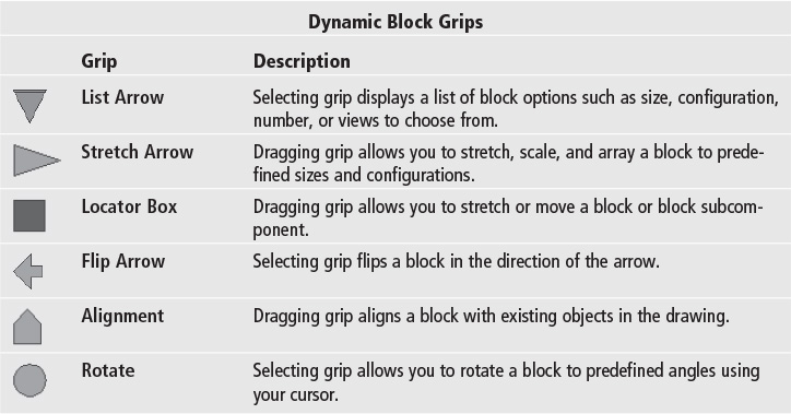
For example, using dynamic block technology, one single block of an architectural-type door for a floor plan can be updated so that you can:
• Switch between different standard door opening angles
• Resize the door using standard door opening and frame widths
• Flip the door horizontally or vertically about the center of the door opening
• Automatically align the door along a wall
For More Details
See page 295 in Chapter 7 for more information about using grips to modify objects.
Tip
Many of a block’s dynamic options and features can be set prior to inserting the block using the Properties palette instead of using grips after the block is inserted. If you turn on the Properties palette and select a dynamic block on a tool palette, the dynamic block options that can be updated prior to insertion are listed under the Custom category.
Using the List Arrow grip, the door opening angle can be set to 30°, 45°, 60°, 90°, or even appear closed as shown in Figure 16-67.
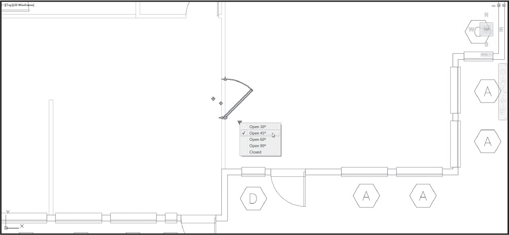
Using the Stretch Arrow grip, you can resize the door to any predefined opening size (24″, 28″, 30″, 32″, 36″, or 40″) as shown in Figure 16-68.
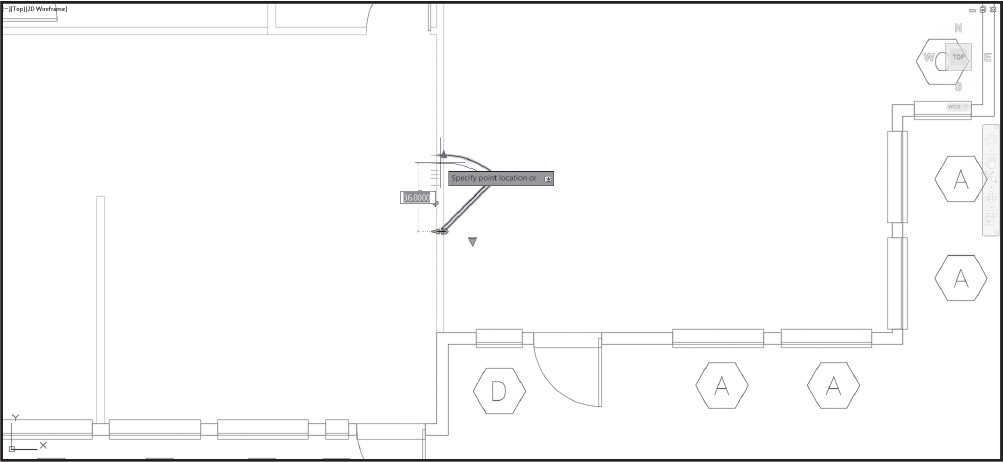
Using the Flip Arrow grip, you can mirror the door about the center of the opening either horizontally or vertically as shown in Figure 16-69.

With the Alignment grip, you can drag the door near a wall, and it will automatically align itself along the same angle as the wall as shown in Figure 16-70.
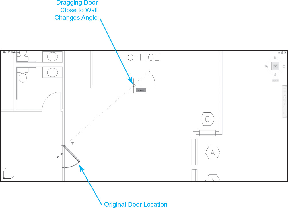
Tip
The dynamic block alignment feature also works as the dynamic block is inserted so that you can instantly align doors, windows, and other blocks with existing objects in your drawing.
Unfortunately, covering all the dynamic block update options and features is beyond the scope of this text, as is the complex process involved in creating a dynamic block. Because of their complex nature, AutoCAD includes a special Block Editor environment for creating and updating dynamic blocks that has its own set of “authoring” palettes where you define parameters and actions. You might have started it accidentally at some point and wondered what it was because it changes the ribbon and the color of the AutoCAD background as shown in Figure 16-71.
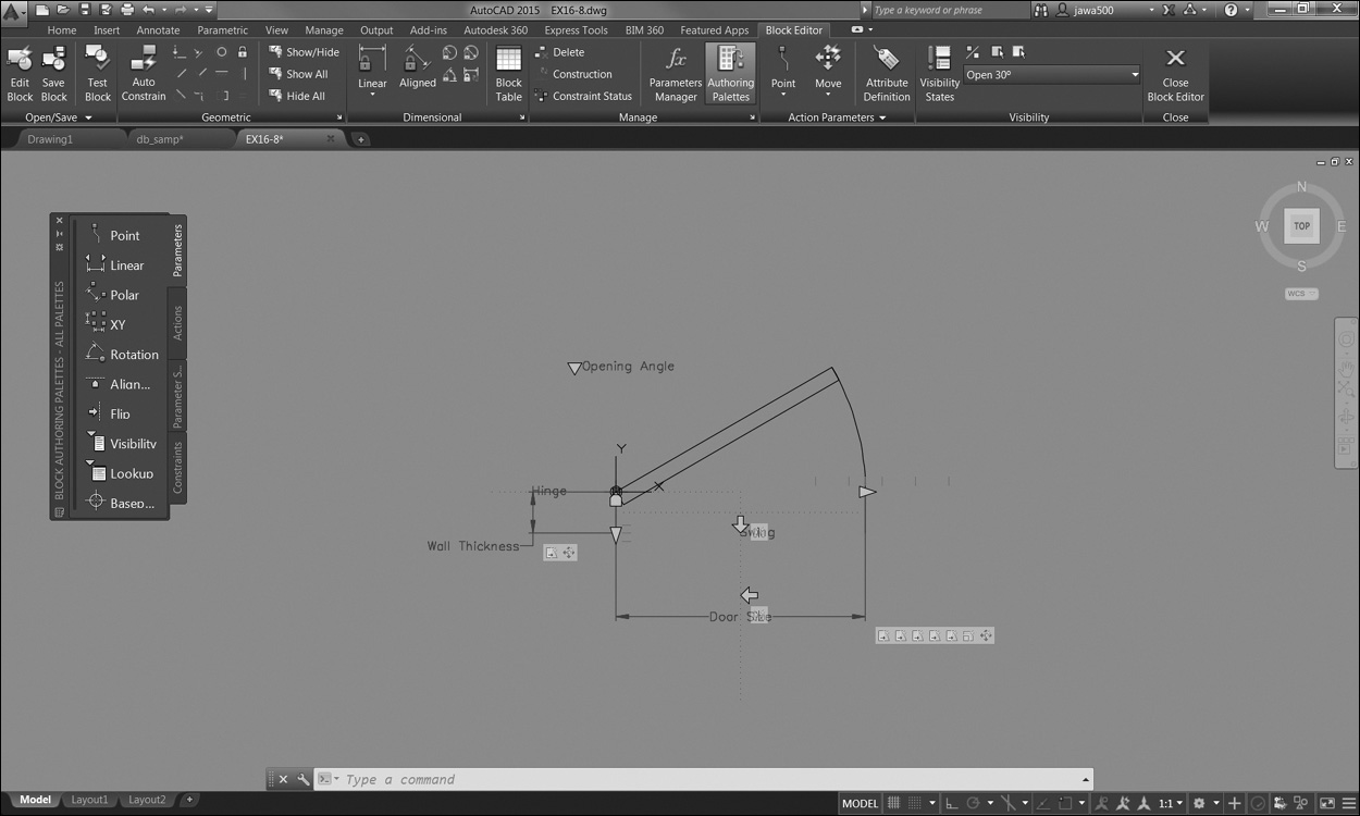
If this happens, the best thing to do at this point is to select the Close Block Editor button on the ribbon at the top of the screen to exit the editor and get back to your drawing.
Fortunately, AutoCAD has many sample dynamic blocks available on the sample tool palettes that come with AutoCAD (shown earlier in Figure 16-60) that you can play with and use in your drawings.
Exercise 16-14 Using Dynamic Blocks
![]() Continue from Exercise 16-13.
Continue from Exercise 16-13.
![]() Select one of the Door-Imperial blocks inserted in Exercise 16-12 so that dynamic grips are displayed.
Select one of the Door-Imperial blocks inserted in Exercise 16-12 so that dynamic grips are displayed.
![]() Select the Alignment grip, and align the door with the vertical wall by dragging it with your mouse close to the wall until the block rotates 90° and is aligned with the wall as shown in Figure 16-70. Select a point to locate the door on the wall.
Select the Alignment grip, and align the door with the vertical wall by dragging it with your mouse close to the wall until the block rotates 90° and is aligned with the wall as shown in Figure 16-70. Select a point to locate the door on the wall.
![]() Select the List Arrow grip to display all the door opening angle options, and select Open 45° so that the door angle is updated as shown in Figure 16-67.
Select the List Arrow grip to display all the door opening angle options, and select Open 45° so that the door angle is updated as shown in Figure 16-67.
![]() Select the vertical Stretch Arrow grip, and stretch the door so that the door opening is 36″ wide as shown in Figure 16-68.
Select the vertical Stretch Arrow grip, and stretch the door so that the door opening is 36″ wide as shown in Figure 16-68.
![]() Select the horizontal Stretch Arrow grip, and stretch the door so the door frame width is 4″ wide, the same as the wall thickness.
Select the horizontal Stretch Arrow grip, and stretch the door so the door frame width is 4″ wide, the same as the wall thickness.
![]() Select the vertical Flip Arrow grip, and mirror the door horizontally as shown in Figure 16-69.
Select the vertical Flip Arrow grip, and mirror the door horizontally as shown in Figure 16-69.
![]() Save the drawing.
Save the drawing.
Autodesk Content Explorer
Autodesk Content Explorer allows you to instantly access one or more drawings to find different drawing content such as blocks, layers, linetypes, text styles, and more. Unlike DesignCenter, Content Explorer relies on an index that is constantly updated so you can search for information in a multitude of folders on your local computer, network servers, and even the Internet and have the results returned instantaneously. You can display the Content Explorer palette via the Explore button on the Add-ins tab of the ribbon (see Figure 16-72).
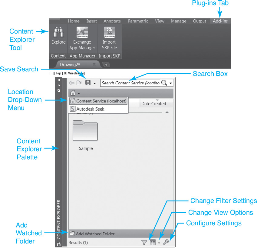
The Search box at the top of the Content Explorer palette allows you to search for drawing content on your local computer, network, and the Autodesk Seek website. The Location drop-down menu on the upper left shown in Figure 16-72 allows you to select which location to search.
Note
In addition to blocks, you can search for text strings and even block attributes.
Once search results are displayed, you can simply drag and drop selected content directly into your current drawing just like you do with DesignCenter. Right-clicking on content will display a shortcut menu similar to the one shown in Figure 16-73 with different options depending on the content type. For example, if you are searching for a particular text string or attribute value, you can right-click to open the source file and zoom directly to the found text.
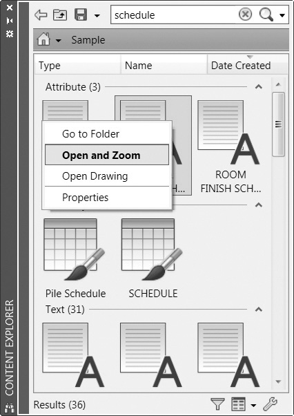
You can also double-click on content to automatically run its default command or option. The default command is always the bold item indicated on the right-click shortcut menu described above.
You can control what and how content is displayed via the Change filter settings and Change view options buttons on the bottom right of the palette (see Figure 16-72). Using the filter options you can reduce the info glut by limiting the content to only those objects you’re interested in. The view options allow you to control the icon size, switch between detailed and thumbnail views, group different results, and turn on/off the text labels and column headers.
Search Locations
In order to provide the optimum performance when doing complex searches, Autodesk Content Explorer searches for information only in specific locations that have been included in an index that is constantly updated to reflect any changes. Default locations include the AutoCAD Sample folder, downloaded content folders, and the Autodesk Seek website. You can add your own local folder(s) to the search index by selecting the Add Watched Folder... button at the bottom of the Content Explorer palette when you are at the Home location (see Figure 16-72).
Tip
You can also include local folders by dragging and dropping them from Windows Explorer into Content Explorer.
You can add one or more network folders to the Content Explorer index, but it requires that the Autodesk Content Service software be installed and running on that network computer in order to maintain a single shared index that everyone can access and search.
Note
The Autodesk Content Service software required to add networked locations to the Content Explorer index can be installed separately via the AutoCAD 2015 installation program under the Tools and Utilities options.
The Autodesk Seek location allows you to browse and search for content online on the Autodesk Seek website so you can find files from specific manufacturers or about different product types without going to an external website as shown in Figure 16-74.
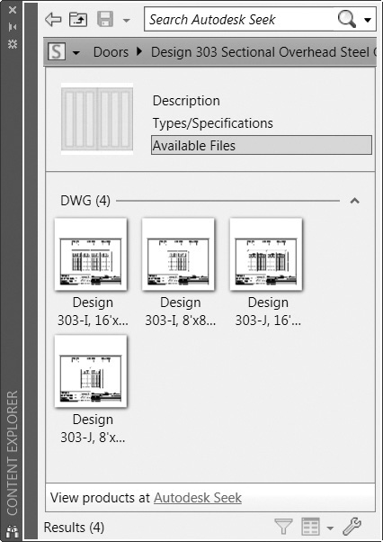
Chapter Summary
In this chapter, we learned how to create, insert, and manage blocks. Blocks have been around for a long time and are one of the primary features of most CAD software because you can draw something once and use it many times. This simple capability provides three basic but overwhelmingly important benefits:
• Increased productivity Draw it once and use it over and over again.
• Increased precision If you take the time to draw a block right the first time, it is always correct for each subsequent insertion.
• Increased standards compliance Draw a block that you are sure meets the standards of your organization, and then distribute it so that it is used throughout a project.
Many blocks already exist that can be downloaded from the Internet from various manufacturers, suppliers, trade organizations, and others. The Autodesk Seek feature provides access to much of this content. It is even possible to download complete symbol libraries of blocks.
Take the time to consider when to make a block. If you are going to use something in a drawing more than three times, it might be a good candidate for a block. Think about creating a block library and what it might look like. You can create several separate block drawing files and organize them in folders so they can be inserted using Windows Explorer, or you might put all the blocks in a single drawing file and access them using DesignCenter. Each approach has its pros and cons.
The ability to add nongraphical alphanumeric intelligence to your drawings in the form of block attributes is another huge productivity enhancer. Now you can create a single block definition and assign different alphanumeric information each time it is inserted—visible or invisible! Using invisible attributes, you can attach important alphanumeric information to blocks that will not plot but can be extracted to an AutoCAD table, text file, spreadsheet, or even database. What you do with this information is up to your own imagination.
Accessibility is the key to utilizing blocks productively. There are many different ways to organize and provide blocks. Tool palettes are convenient and highly customizable, whereas DesignCenter is unwieldy but it provides access to information that tool palettes can’t. Alternatively, sometimes dragging and dropping a file from Windows Explorer is the way to go. Autodesk Content Explorer can do all of the above, usually quicker too, but you must first create an index of all the information you wish to access. You will find yourself mixing and matching different block tools to meet your needs at the moment. Take time to investigate AutoCAD’s dynamic block samples and glimpse the symbol libraries of the future. Now one block can provide a complete symbol library that is just a click away!
Tip
Be careful when downloading any information from the Internet. You will want to examine any blocks you download and check them for accuracy and standards compliance. Just like anything on the Internet, there is some bad information to be found—you must take the time to separate the wheat from the chaff.
1. An AutoCAD block is best described as a:
a. Hatch pattern
b. Named collection of AutoCAD objects treated as a single complex object
c. Title border
d. Group of layers
2. The advantage of using blocks in a drawing is:
a. Reduced drawing size
b. Increased accuracy
c. Ease of updating drawings
d. All of the above
3. When inserting an annotation-type block, it is necessary to:
a. Put it on a text layer
b. Scale the block by the drawing scale
c. Set the text style
d. All of the above
4. A block attribute is:
a. An object property such as layer, color, linetype, or lineweight
b. A scale
c. A rotation
d. Dynamic text used to store alphanumeric data
5. Defining a block within another block is referred to as:
a. Block assembly
b. Impossible
c. Block reference
d. Block nesting
6. Block subobjects created on Layer 0 with all their object properties set to ByLayer assume what current object property when the block is inserted?
a. Color
b. Lineweight
c. Layer
d. All of the above
7. Unit blocks allow you to:
a. Maintain consistent grid and snap settings
b. Scale a block differently in the x and y scale for different results
c. Transfer blocks from one unit system to another
d. All of the above
8. Dragging and dropping a drawing from Windows Explorer into a drawing using the right mouse button allows you to:
a. Open a drawing
b. Insert a drawing as a block
c. Attach an xref
d. All of the above
9. The command that allows you to turn invisible attributes on so they are displayed in the drawing is:
a. ATTREQ
b. ATTDIA
c. ATTDISP
d. -ATTEDIT
10. The command that allows you to update the value of an attribute is:
a. -ATTEDIT
b. BATTMAN
c. EATTEDIT
d. a and c
Matching
Write the number of the correct answer on the line.
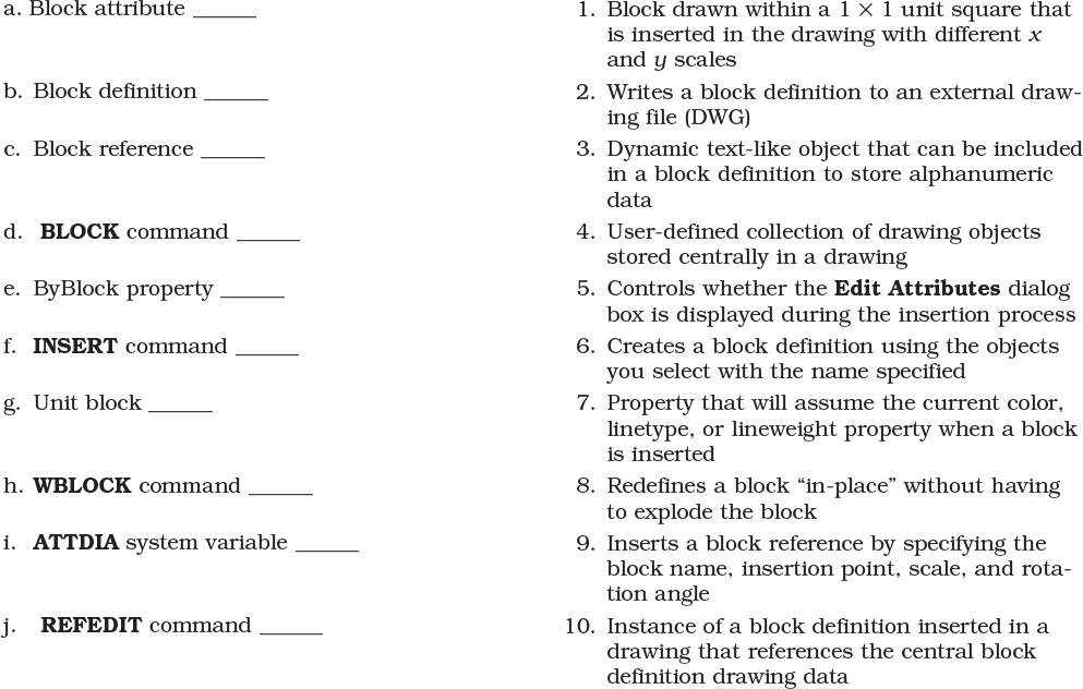
True or False
Circle the correct answer.
1. True or False: Blocks can be defined so that they cannot be exploded.
2. True or False: It is not possible to create a block with the same name as a block already defined in a drawing.
3. True or False: A block definition cannot be inserted in another drawing until it is exported as a drawing file.
4. True or False: It is possible to always specify a different x, y, and z scale when inserting a block.
5. True or False: When inserting a drawing file (DWG) as a block, both model space and paper space information are included.
6. True or False: It is possible to export all the objects in a drawing automatically using the WBLOCK command.
7. True or False: Attributes can be located automatically so that they align below the previous attribute.
8. True or False: It is possible to insert an AutoCAD field in an attribute value.
9. True or False: The -ATTEDIT command allows you to update multiple attributes with the same value at one time.
10. True or False: A table created using the Data Extraction wizard can be set to update automatically if a referenced attribute value changes.
Chapter Projects
![]() Project 16-1: Classroom Plan, continued from Chapter 15 [BASIC]
Project 16-1: Classroom Plan, continued from Chapter 15 [BASIC]
1. Open drawing P15-1 from Chapter 15.
2. Create separate blocks for each of the items shown in Figure 16-75 using the insertion points indicated by the “X” symbol.
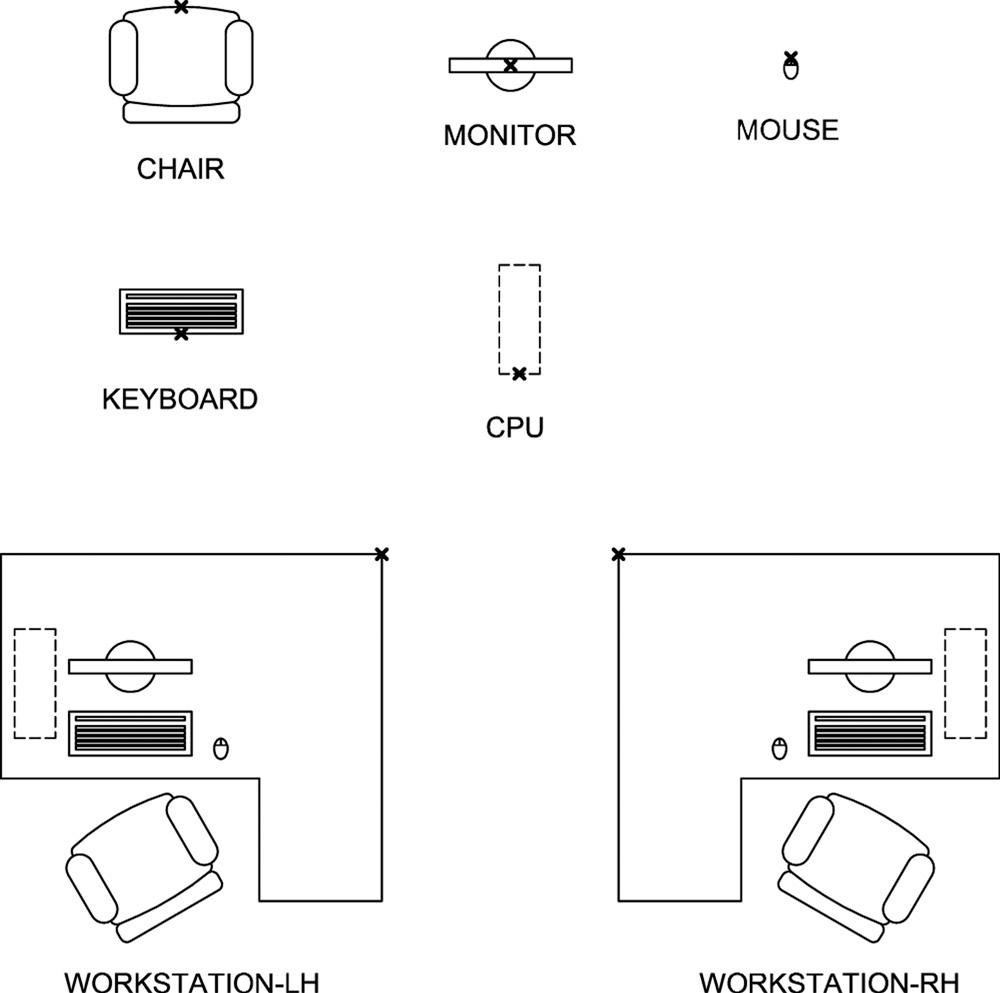
3. Create blocks for the left- and right-hand workstations as shown in Figure 16-75 using the insertion points shown. Use the blocks created in the previous step as components of the workstation blocks.
4. Replace the original workstations with the new workstation blocks.
5. Save your drawing as P16-1.
![]() Project 16-2: B-Size Mechanical Border, continued from Chapter 15 [INTERMEDIATE]
Project 16-2: B-Size Mechanical Border, continued from Chapter 15 [INTERMEDIATE]
1. Open template file Mechanical B-Size.DWT from Chapter 15.
2. Create the title block attribute definitions shown in Figure 16-76. Place the attributes on the Title layer. Use the definitions shown in the following table:
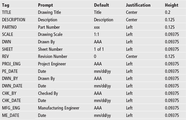
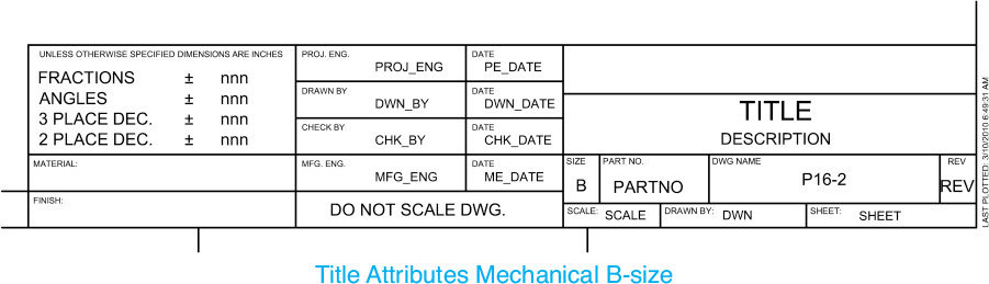
3. Use the WBLOCK command to create a block/drawing named Title Attributes Mechanical B-Size.DWG by selecting the attributes defined above and shown in Figure 16-76 using the following settings:
a. Set the Base point to 0,0,0.
b. Set the Objects option to the Delete from drawing setting so the attributes are deleted.
c. Set Insert units to Unitless.
4. Use the WBLOCK command to create a block/drawing named Mechanical B-Size.DWG by selecting all the remaining title border line work and static text that never changes using the following settings:
a. Set the Base point to 0,0,0.
b. Set the Objects option to the Delete from drawing setting so the attributes are deleted.
c. Set Insert units to Unitless.
5. Close the drawing template. Do not save changes to the drawing template.
![]() Project 16-3: Architectural D-Size Border, continued from Chapter 15 [ADVANCED]
Project 16-3: Architectural D-Size Border, continued from Chapter 15 [ADVANCED]
1. Open template file Architectural D-Size.DWT from Chapter 15.
2. Create a layer named A-ANNO-TTLB-ATTS with default properties. Set its color to red and make it the current layer.
3. Replace all the updateable title block text with the attribute definitions shown in Figure 16-77 and defined in the following table:
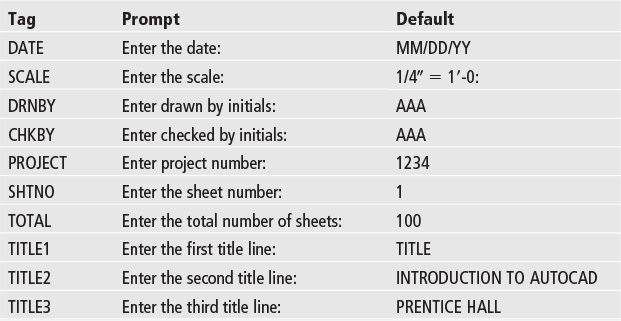
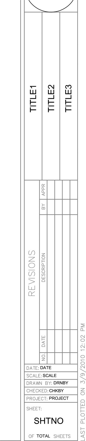
4. Use the WBLOCK command to create a block/drawing named Title Attributes Architectural D-Size.DWG by selecting the attributes defined above and shown in Figure 16-77 using the following settings:
a. Set the Base point to 0,0,0.
b. Set the Objects option to the Delete from drawing setting so the attributes are deleted.
c. Set Insert units to Unitless.
5. Use the WBLOCK command to create a block/drawing named Architectural D-Size.DWG by selecting all the remaining title border line work and static text that never changes using the following settings.
a. Set the Base point to 0,0,0.
b. Set the Objects option to the Delete from drawing setting so the objects are deleted.
c. Set Insert units to Unitless.
Note: Do not include the graphic scale in the upper right-hand corner as part of title block definition!
6. Close the drawing template. Do not save changes to the drawing template.
![]() Project 16-4: Socket Head Cap Screws, continued from Chapter 12 [INTERMEDIATE]
Project 16-4: Socket Head Cap Screws, continued from Chapter 12 [INTERMEDIATE]
1. Open drawing P12-2 from Chapter 12.
2. Create blocks from the fasteners created for Chapter 12 using the following settings:
a. Name the block as indicated in the table shown in Figure 16-78. Do not include any text in the block definition.
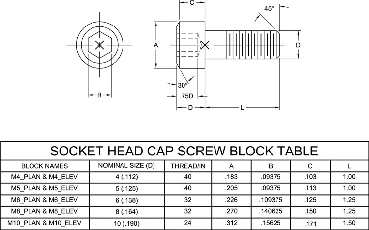
b. Specify the base point shown with “X” in Figure 16-78.
c. Select the Convert to block option so the block is converted in place.
d. Select the Allow exploding option.
3. Save the drawing as Socket Head Cap Screws but leave the drawing open.
4. Start a new drawing using the acad.dwt template.
5. Start DesignCenter, and select the Open Drawings tab.
6. Select the plus symbol (+) next to Socket Head Cap Screws.dwg to expand the tree.
7. Select the Blocks icon so that the fastener blocks you created in step 2 are displayed in the content area on the right.
8. Practice dragging and dropping fastener symbols into your drawing using both the left and right mouse buttons.
9. Double-click on a block to display the Insert dialog box.
![]() Project 16-5: Structural Steel Symbol Library [ADVANCED]
Project 16-5: Structural Steel Symbol Library [ADVANCED]
1. Start a new drawing using the acad.dwt template.
2. Draw eight wide flange shapes using the designation and dimensions in the following steel table using the wide flange profile shown in Figure 16-79.
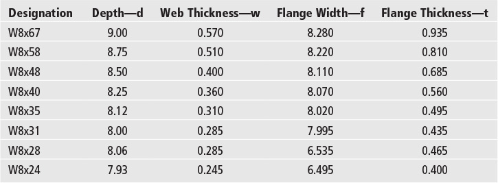
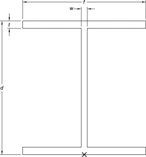
3. Create blocks from the wide flange shapes drawn in step 2 using the following settings:
a. Name the block using its corresponding steel designation (i.e., W8x67). Do not include text or dimensions in the block definition.
b. Specify the base point shown with “X” in Figure 16-79.
c. Select the Convert to block option so the block is converted in place.
d. Select the Allow exploding option.
4. Save the drawing as Structural Steel Symbols but leave the drawing open.
5. Start a new drawing using the acad.dwt template.
6. Start DesignCenter and select the Open Drawings tab.
7. Select the plus symbol (+) next to Structural Steel Symbols.dwg to expand the tree.
8. Select the Blocks icon so that the structural steel blocks you created in step 3 are displayed in the content area on the right.
9. Practice dragging and dropping structural steel symbols into your drawing using both the left and right mouse buttons.
10. Double-click on a block to display the Insert dialog box.