
Chapter 18. Drawing Management Tools and Utilities
• Understand the backup and autosave settings
• Fix a corrupt drawing
• Purge a drawing of unused data
• Import and export different drawing file types
• Copy and paste information between different software applications
• Use object linking and embedding objects in AutoCAD drawings
• Automate repetitive tasks using the Action Recorder
• Use the Measure tools
• Use the QuickCalc calculator
• Use web-based collaboration tools
Introduction
Successful AutoCAD drawing management requires thorough attention to drawing file creation, maintenance, saving, and naming conventions. Drawing management also includes addressing corrupt drawing files, importing and exporting various CAD drawing formats, as well as combining and sharing data using the Windows Clipboard feature or object linking and embedding (OLE). In this chapter, we will examine the AutoCAD drawing utilities and additional drawing management procedures to use when different source applications are needed to increase productivity. We will also look at automating repetitive tasks using the Action Recorder, retrieve useful info about your drawing using the Measure tools, and introduce AutoCAD’s QuickCalc calculator. In addition, preserving the data integrity of your drawings by deleting unnecessary duplicate objects is explored, and we take a look at AutoCAD’s web-based collaboration tools.
Drawing File Backup and Recovery
Anyone who has used a computer has undoubtedly experienced computer problems. Operating systems that lock up, programs that stop responding, viruses, power outages, and equipment failures are a routine part of working with computers. How do you protect your drawings, which represent many hours of valuable work? For starters, safe computing practices such as regular backups, up-to-date antivirus and anti-spyware software scans, and routine computer maintenance can greatly reduce the risk of data loss. AutoCAD offers some additional ways of backing up your design data as well as some tools to help monitor file integrity and recover lost design data.
File Safety Precautions
The File Safety Precautions area of the Open and Save tab of the Options dialog box allows you to control some of these backup and file recovery options (see Figure 18-1).
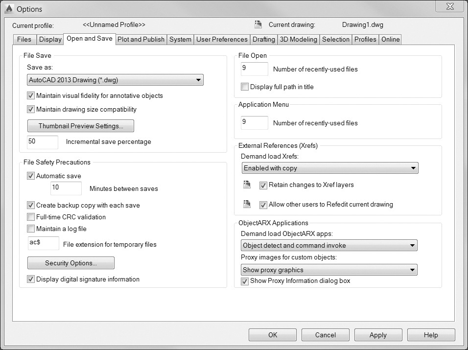
Backup Files
By default, when you save a drawing in AutoCAD, the file is saved with a DWG file extension. The previously saved version of that drawing is renamed with a BAK file extension. For example, you have a drawing called A-06.DWG. When you open that drawing, make changes to it, and then save your drawing, the previously saved file is renamed A-06.BAK, and the new changes are saved to A-06.DWG. If a BAK file already exists, it is overwritten with the new BAK file.
If you are unable to open your current drawing, or if you need to recover changes made to your drawing, you can simply rename the BAK file extension to DWG and open the backup file in AutoCAD. You may want to change the file name as well to avoid confusion. For example, you have two files: A-06.BAK and A-06.DWG. You wish to open the BAK file to recover some objects you deleted. To avoid confusing the two files, you can rename the BAK file to A-06-Backup.DWG and then open the backup file in AutoCAD.
By default, AutoCAD has backup files enabled. To disable the backup file creation, remove the check from the Create backup copy with each save box in the Open and Save tab of the Options dialog box (see Figure 18-1).
Autosave Files
Backup files (BAK) are created only when you save your drawing. For this reason, it’s considered good practice to save your drawing often. However, there are times when AutoCAD quits before you have the opportunity to save. To help recover from these instances, AutoCAD can automatically save your drawing file at regular intervals. This is known as an autosave. By default, AutoCAD does this every 10 minutes.
autosave: The automatic saving of your drawing by AutoCAD at regular intervals. The default save interval is 10 minutes.
Files created with the Autosave feature are considered temporary files. When AutoCAD performs an autosave, it assigns a name consisting of the file name combined with a random number and the file extension .SV$. These files are placed in the Windows Temp folder and are created as a failsafe to recover drawing information in the event of a program failure or power failure. If your drawing is closed normally, these temporary save files are deleted. If the drawing does not close normally, the temporary files are retained and can be renamed and opened in AutoCAD.
When you start a command, AutoCAD looks at the time since the last autosave was done. If the time is greater than the autosave interval, AutoCAD will do an autosave before it starts your command. AutoCAD displays a message when it is performing an automatic save while you are working. Following is an example:
Automatic save to C:UsersPaulappdatalocal empAS-01_1_1_7542.sv$
If you do not see a message from AutoCAD, you should check that the Autosave feature is enabled and that a reasonable save interval is set. You can set this in the Automatic save box in the Open and Save tab of the Options dialog box (see Figure 18-1). The Automatic Save File Location setting in the Files tab of the Options dialog box allows you to change the location where the files are saved.
Temporary Files
In addition to the autosave files, AutoCAD also creates temporary files in the Windows Temp folder. These temporary files are used by AutoCAD and Windows to manage data while your drawing file is open. These keep track of undo and redo information as well as store changes to your drawing in between saves. These files are given a random name with an .AC$ file extension.
As with the autosave files (.sv$), when a drawing is closed normally, these temporary files are deleted. However, if a drawing is not closed properly, these temporary files are retained. They can also be renamed as .DWG and opened in AutoCAD. Since these files are randomly named, finding the exact file you are looking for can be hit-or-miss. Also, there is no guarantee that the information you’re seeking will be contained in these files, but it does give you some additional places to look if you lose valuable design information.
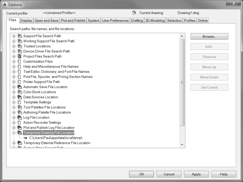
The File extension for temporary files box in the Open and Save tab of the Options dialog box (see Figure 18-1) allows you to change the file extension of these temporary files. Also, the Temporary Drawing File Location setting in the Files tab of the Options dialog box allows you to change the location where these temporary files are stored (see Figure 18-2).
Corrupt Drawing Objects
Drawing corruption can occur when a drawing object is not defined properly within the drawing file. This can happen when importing drawing information from other CAD applications, if you are using custom software applications inside AutoCAD, or if AutoCAD closes without saving your drawing.
Corrupt objects can cause a variety of problems from AutoCAD locking up to a drawing failing to load properly. When you consider that drawings can be used as xrefs and that nested references may be used, a single corrupt object can wreak havoc on a design project.
If you suspect that corrupt objects may be causing a problem, AutoCAD allows you to turn on a cyclic redundancy check (CRC) to monitor all new objects created during the drawing session. This option will check all new objects to ensure they are well defined before AutoCAD adds them to the drawing. This is set by checking the Full-time CRC validation box in the Open and Save tab of the Options dialog box (see Figure 18-1). This checking can slow down the drawing process slightly, so this option should be turned on only as needed to help track down the source of corrupt drawing objects.
Recovering Lost or Corrupt Drawings
If your AutoCAD session locks up or closes before you can save your drawing, AutoCAD provides some tools for recovering lost drawing information and fixing corrupt drawings.
Drawing Recovery Manager |
|
Application Menu: |
Drawing Utilities
|
Menu: |
File | Drawing Utilities | Drawing Recovery Manager... |
Command Line: |
DRAWING-RECOVERY |
Command Alias: |
None |

Note
Although these tools can recover many damaged or corrupt drawings, they are not guaranteed to recover all lost information. Remember to save often and back up critical drawing files on a regular basis.
The Drawing Recovery Manager
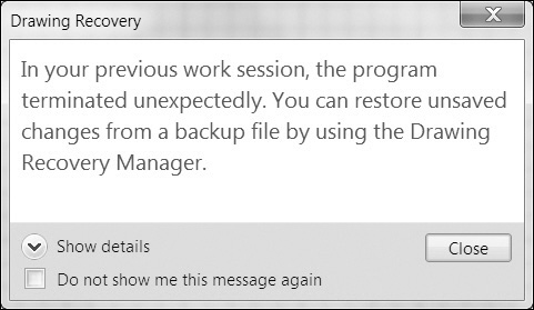
If your AutoCAD session ends prematurely, the next time you start AutoCAD, it will display a message about drawing recovery (see Figure 18-3), and the Drawing Recovery Manager (see Figure 18-4) will start automatically. You can also start the Drawing Recovery Manager with the DRAWINGRECOVERY command.
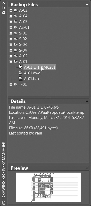
The Drawing Recovery Manager provides an easy way to examine backup and autosave files. When the Drawing Recovery Manager starts, it searches for backup (BAK) and autosave (SV$) files along with their associated DWG files and displays them in the Drawing Recovery Manager palette (see Figure 18-4).
Note
The Drawing Recovery Manager will start automatically every time you start AutoCAD until you remove the drawings from the Backup Files area.
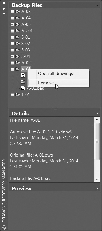
The Backup Files area displays all the backup, autosave, and drawing files associated with a given drawing. Selecting one of the listed files will display information about the file in the Details area and a preview of the file in the Preview area.
You can open the selected file by double-clicking it or choosing Open from the right-click menu. This allows you to examine in detail the various backup files. When you find the one you want to keep, save it using the file name of your choosing. You can then remove the drawing from the Drawing Recovery Manager by selecting the drawing file name folder in the Backup Files area and choosing Remove from the right-click menu (see Figure 18-5).
Fixing Corrupt Drawings
AutoCAD provides two commands to examine and repair corrupt drawing files: AUDIT and RECOVER.
The AUDIT and RECOVER commands will both scan a drawing for any corruption and allow you to attempt to correct any problems they find. The RECOVER command allows you to select any drawing file to scan. The AUDIT command scans only the currently open drawing file. In addition, the AUDIT command gives you the option of just scanning the file without attempting to correct the problems.
Audit |
|
Application Menu: |
Drawing Utilities
|
Menu: |
File | Drawing Utilities | Audit |
Command Line: |
AUDIT |
Command Alias: |
None |

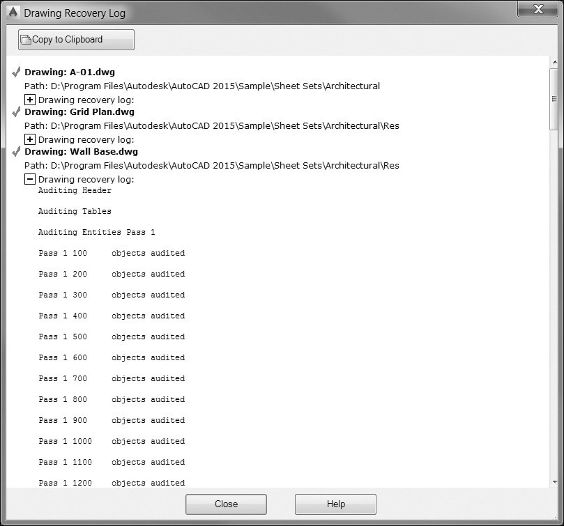
The AUDIT and RECOVER commands operate only on a single drawing file. If the drawing has any xrefs, the xrefs will not be scanned for problems. If you wish to scan a drawing and all of its associated xrefs, you should use the RECOVERALL command. The RECOVERALL command scans the drawing and any xrefs attached to the drawing. The RECOVERALL command also displays a report at the end of the command showing the results for each drawing it scans (see Figure 18-6).
Recover |
|
Application Menu: |
Drawing Utilities
|
Pull-down Menu: |
File | Drawing Utilities | Recover... |
Command Line: |
RECOVER |
Command Alias: |
None |

Cleaning Up Drawing Files
As you have seen, AutoCAD drawings consist of both graphical and nongraphical elements. Layer settings, block definitions, linetypes, text styles, plot styles, table styles, dimension styles, and other nongraphical elements can be stored in a drawing, even if they may not be used within the drawing. It is possible to have empty layers, unused linetypes, dimension styles, etc.
Although these elements can reside in the drawing without being used, they do add to the size of the drawing file and can add complexity to a drawing. For example, a CAD layering standard may have hundreds of potential layers, but only a handful of them are used in any given drawing. Similarly, you may have a block library that consists of many symbols, but you may use only a few in any single drawing. There is no need to have all of these extra settings and block definitions stored with every drawing.
To help manage these various definitions and style settings, AutoCAD provides the PURGE command to view unused styles and definitions and remove them from the drawing.
Recover with Xrefs |
|
Application Menu: |
Drawing Utilities
|
Menu: |
File | Drawing Utilities | Recover drawingand xrefs... |
Command Line: |
RECOVERALL |
Command Alias: |
None |
The PURGE Command
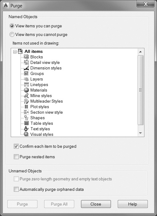
When you start the PURGE command, AutoCAD displays the Purge dialog box (see Figure 18-7). This dialog box has a list of the various items that can be purged from a drawing. By default, AutoCAD shows you all the items that can be purged. A plus (+) symbol next to any item denotes a category that contains items that can be purged. Clicking on the + symbol expands the tree to show you the specific items. To purge an item, simply select the object from the list and choose the Purge button. You can select multiple items using either <Ctrl> or <Shift> while selecting items. To purge all unused objects from a drawing, choose the Purge All button. Placing a check in the Confirm each item to be purged check box will cause AutoCAD to prompt you before it purges each object.
Purge |
|
Application Menu: |
Drawing Utilities
|
Menu: |
File | Drawing Utilities | Purge |
Command Line: |
PURGE |
Command Alias: |
None |

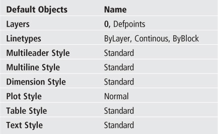
You can also choose to display items that cannot be purged by selecting the View items you cannot purge button. Keep in mind that only unused objects can be purged from the drawing. When the View items you cannot purge button is selected, you will not be able to purge any objects. In addition, the following default AutoCAD objects cannot be purged from a drawing.
Purging Nested Items
Some objects may be nested, meaning that unused objects are dependent on other unused objects. For example, you may have a block definition that contains an unused layer definition. In order for the layer definition to be purged, the block definition containing the layer definition must first be purged.
To purge nested items, you can keep selecting items and choosing Purge, or you can check the Purge nested items box. When this box is checked, all selected items and any items nested below them will also be purged.
To quickly purge all unused objects from your drawing, start the PURGE command, check the Purge nested items box, turn off the Confirm each item to be purged item, and choose Purge All.

Note
It is possible to purge zero-length geometry and text objects that consist only of spaces by selecting the check box in the Unamed Objects area at the bottom of the Purge dialog box. Selecting the Automatically purge orphaned data checkbox will purge DGN linetypes and orphaned DGN linetype data that can accumulate while copying and pasting from drawings containing DGN linetypes.
Tip
Sometimes you may have a layer that appears to be unused but cannot be purged. Layers that are frozen within a layout viewport (VP Freeze in the Layer dialog box) cannot be purged until they are thawed within that viewport.
Working with Different CAD File Formats
At some point, you may need to work with a drawing file created in another drafting program or use AutoCAD data in another software application. AutoCAD has the ability to read and write a number of different raster and vector file formats. Importing and exporting various file formats can be done in a variety of ways.
Exporting to DWF/PDF Files
In Chapter 15, we saw how it is possible to create DWF/DWFx (Design Web Format) and PDF (Adobe Portable Document Format) files using the PLOT command. It is also possible to export a file directly to the DWF/DWFx and PDF formats using the tools and settings on the Export to DWF/PDF panel on the Output tab of the ribbon shown in Figure 18-8.
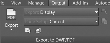
The Export list box at the top of the panel allows you to specify what information to export. In a paper space layout, you can export the current layout or all layouts at one time. In model space, you can export what is currently displayed, the drawing extents, or pick a window area.
The Page Setup list box allows you to control what page setup settings to apply. By default, the current page setup is used. The Override option displays the Page Setup Override dialog box so you can change the paper size, the plot style table (pen assignments), the plot scale, and other plot settings.
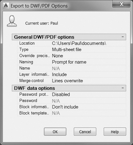
The Export to DWF/PDF Options button displays the Export to DWF/PDF Options dialog box shown in Figure 18-9 so you can control the output settings, such as whether to create a multisheet file or to include layer information.
The Preview button allows you to preview the file before exporting it so you can check it to make sure everything looks correct.
Once all the desired settings and options have been selected and you are ready to export your file, select one of the three export types from the flyout menu on the left (DWFx, DWF, PDF) to display its corresponding Save As dialog box so you can specify a file name and location. All three output formats share a dialog box similar to the Save As PDF dialog box shown in Figure 18-10.
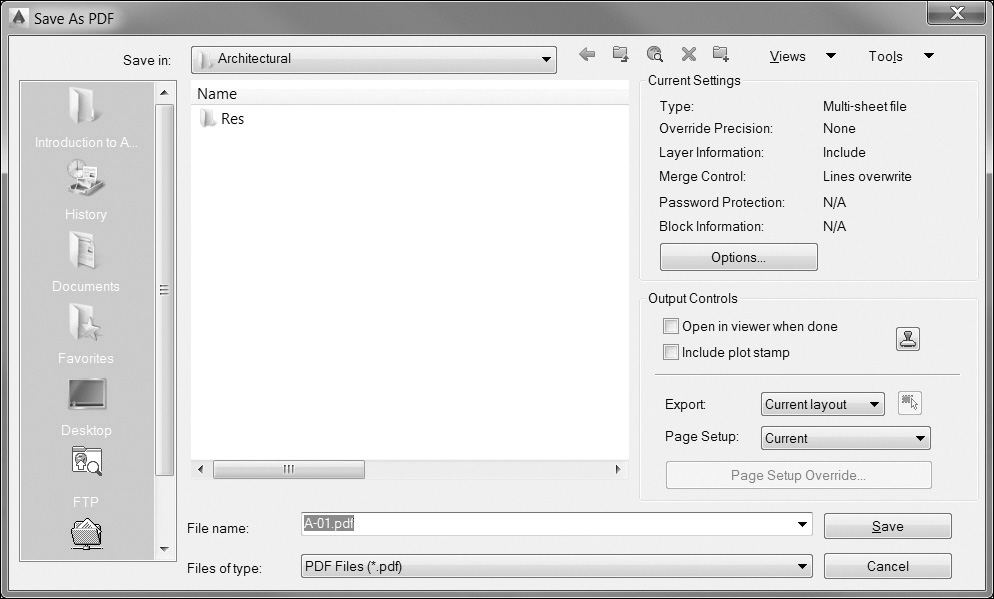
Select the Save button once the file name and location have been specified to export the file. The Plot and Publish Job Complete notification balloon is displayed in the AutoCAD system tray in the lower right-hand corner of the AutoCAD window when AutoCAD is done exporting the file, indicating the success or failure of the export process.
Importing and Exporting Other File Types
The IMPORT and EXPORT commands are the most common ways of reading and writing other file formats. AutoCAD also provides a number of commands that work with specific file formats.
Note
This section will cover some of the basics of importing and exporting various file formats. However, the specifics of working with each individual file type are beyond the scope of this text. If you have a specific file format you need to read or write, please consult the AutoCAD 2015 Help feature and search for your specific file format.
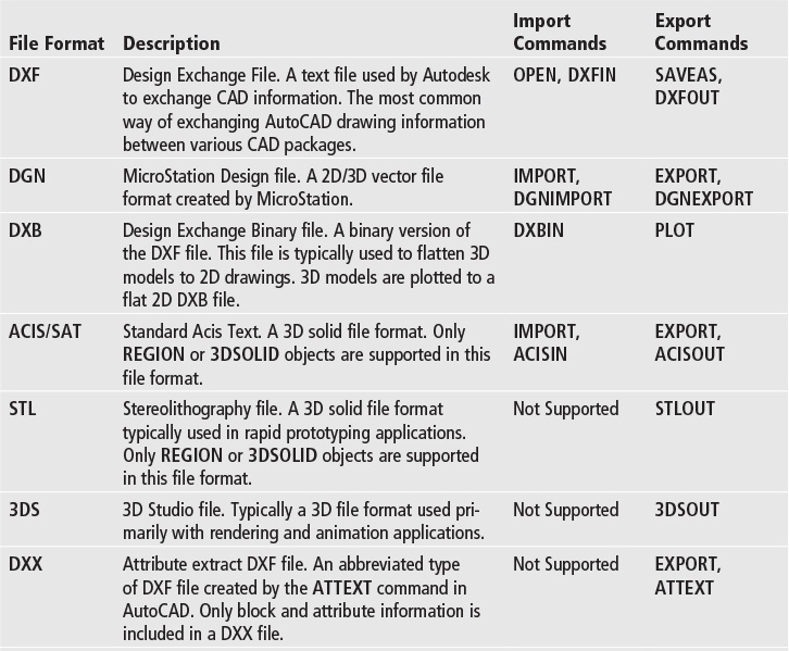
The following table describes the various file formats that AutoCAD supports and the commands that are available to read or write.

The EXPORT Command
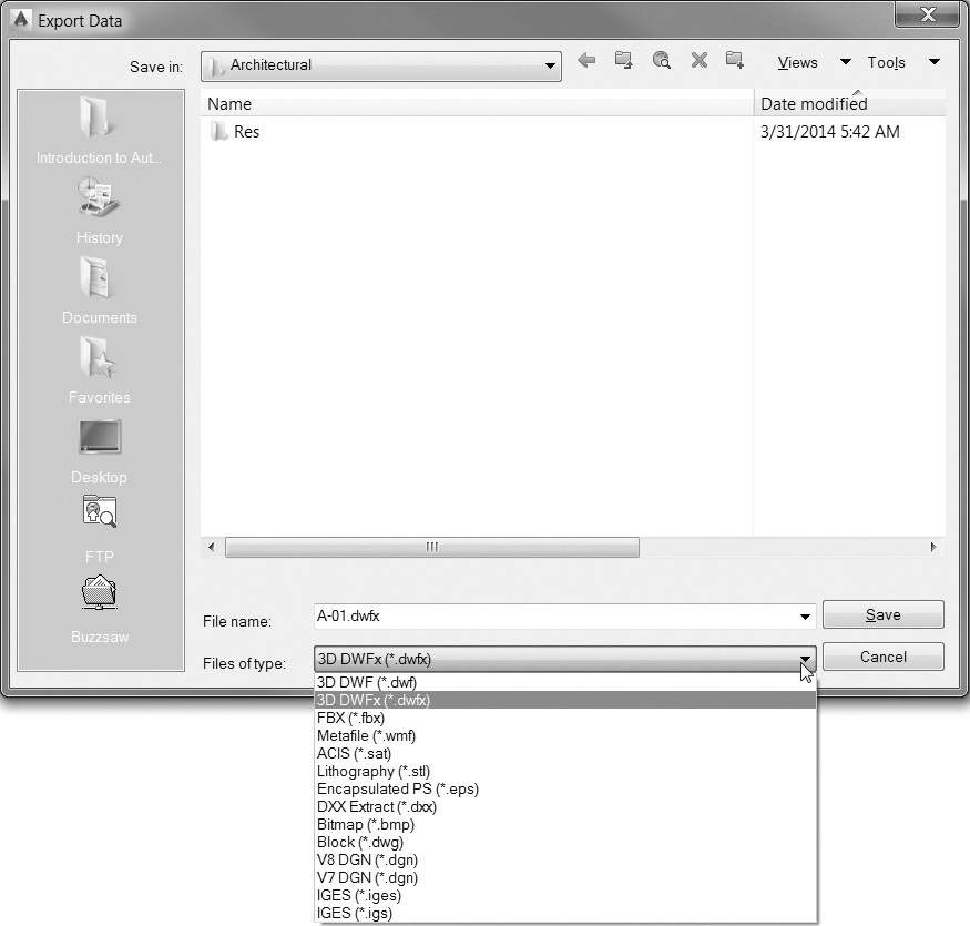
The EXPORT command allows you to export AutoCAD drawing information to various file formats. When you start the EXPORT command, AutoCAD will display the Export Data dialog box (see Figure 18-11) where you can specify the output file type as well as the file name.
Export |
|
Application Menu: |
Other Formats
|
Menu: |
File | Export... |
Command Line: |
EXPORT |
Command Alias: |
EXP |

Once you specify the file name and file type, AutoCAD will prompt you to select the objects you want to export. Once you select the objects to export, press <Enter> to export the objects to the specified file.
Note
The PLOT command also provides some additional ways to export your file to various raster and vector file formats. These file formats include JPG, BMP, PNG, CALS, TIF, TGA, PDF, PCX, and HPGL. These formats require the configuration of plotters via the Add-a-Plotter wizard, which can be accessed with the Add or Configure Plotters... button in the Plot and Publish tab of the Options dialog box.
The IMPORT Command
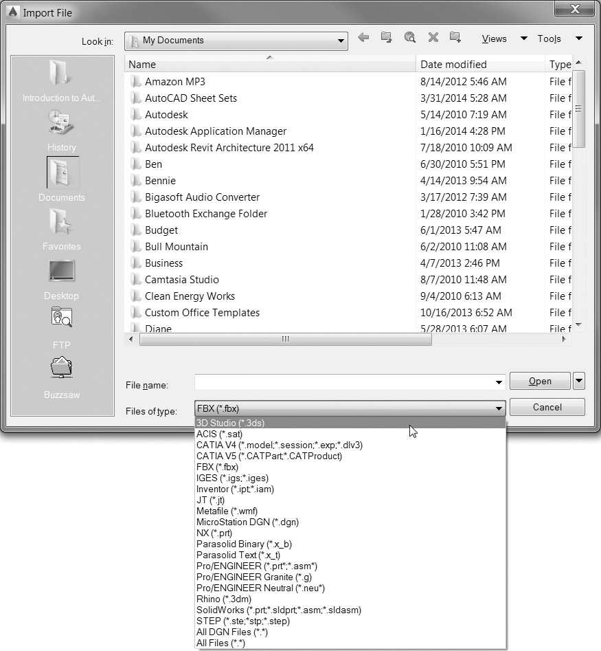
The IMPORT command allows you to convert various file formats to AutoCAD objects. When you start the IMPORT command, AutoCAD will display the Import File dialog box (see Figure 18-12) and allow you to specify the file type as well as the file name.
Import |
|
Ribbon & Panel: |
Insert | Import
|
Menu: |
File | Import... |
Command Line: |
IMPORT |
Command Alias: |
IMP |

Note
Take care when exporting objects from paper space layouts. Because you are prompted to select objects, only selected objects in the current drawing space will be exported. Exporting objects from both model space and paper space is not allowed.
After you specify the file name and file type, AutoCAD imports the data and places it in the drawing. The imported objects are typically converted to a block and placed as a single object, which can then be exploded.
Working with DXF Files
DXF stands for Design Exchange File and is the primary method that AutoCAD uses for importing and exporting data between CAD applications. A DXF file can be either binary or ASCII text (most commonly used) and is widely used and supported by most CAD applications. DXF files can be created in AutoCAD with the SAVEAS or DXFOUT command. The DXFOUT command is actually a command alias for the SAVEAS command.
Note
The specifics of importing a file will vary depending on the type of file selected. See the AutoCAD 2015Help for the specifics of importing each type of file.
Creating a DXF File
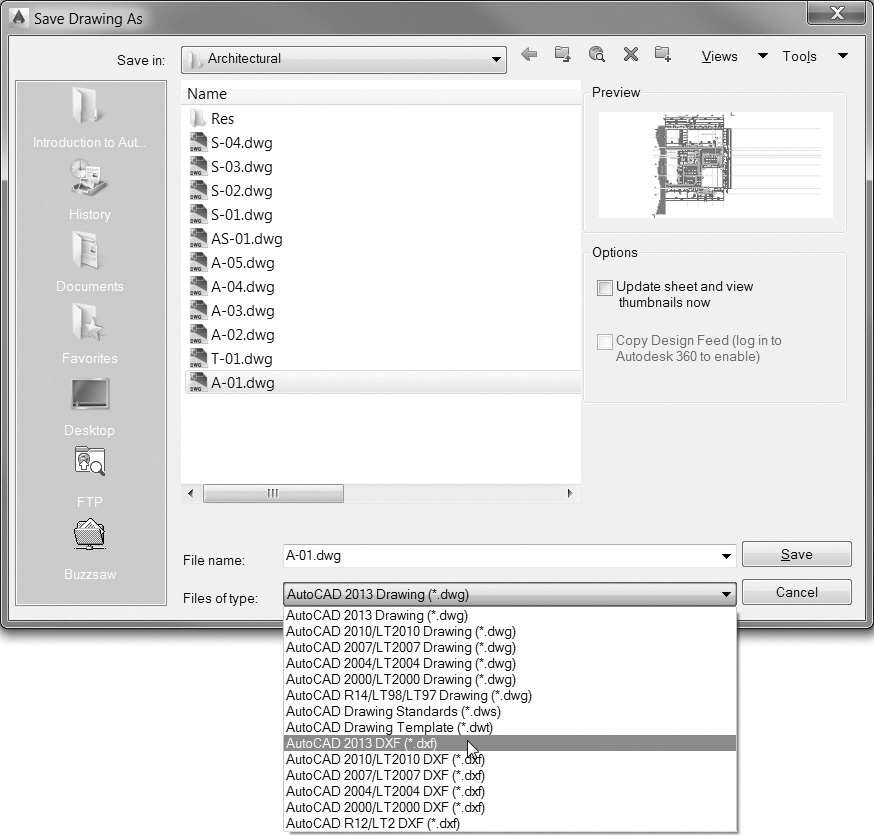
Although the EXPORT command only allows you to export selected objects within a drawing, a DXF file represents the entire drawing (paper space, model space, layers, blocks, etc.). Like the DWG file format, the DXF file format has changed over the various releases of AutoCAD. AutoCAD can currently create DXF files in the following formats: AutoCAD 2013, AutoCAD 2010, AutoCAD 2007, AutoCAD 2004, AutoCAD 2000, and AutoCAD R12.
DWG Convert |
|
Application Menu: |
Save As
|
Menu: |
File | DWG Convert |
Command Line: |
DWGCONVERT |
Command Alias: |
None |

Note
The DXF file format is defined in the AutoCAD Customization Guide section of the AutoCAD 2015Help.
When you start the SAVEAS command, AutoCAD displays the Save Drawing As dialog box (see Figure 18-13). Specify the file name, location, and type of file you wish to create and choose Save.
DWG Convert Tool
The DWG Convert tool allows you to convert a group of drawings to the following AutoCAD DWG release formats: AutoCAD 2013, AutoCAD 2010, AutoCAD 2007, AutoCAD 2004, AutoCAD 2000, and AutoCAD R14.
Keep in mind that some object types are not supported in earlier versions of AutoCAD and will be translated to their earlier object types. For example, ellipses and spline curves are converted to polylines in the R12 file format.
Select the DWG Convert tool to display the DWG Convert dialog box shown in Figure 18-14.
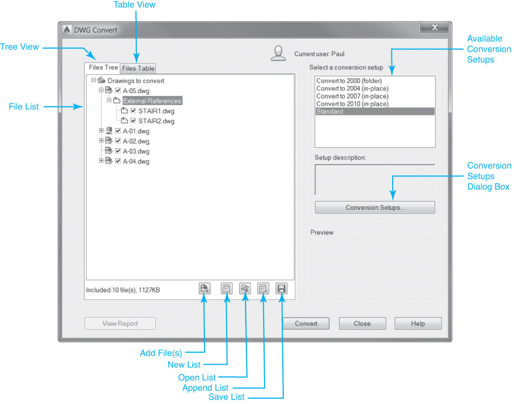
In the DWG Convert dialog box, you select the files you wish to convert along with a conversion setup that controls all of the conversion properties. The buttons along the bottom of the file list box shown in Figure 18-14 allow you to add one or more drawings to convert, make a new list of files, save a list of files, as well as open or append existing file lists. The Conversion Setups... button allows you to add, delete, rename, or modify conversion setups so you can manage and maintain multiple setups for multiple clients and/or consultants.
The Modify Conversion Setup dialog box shown in Figure 18-15 controls all of the conversion settings.
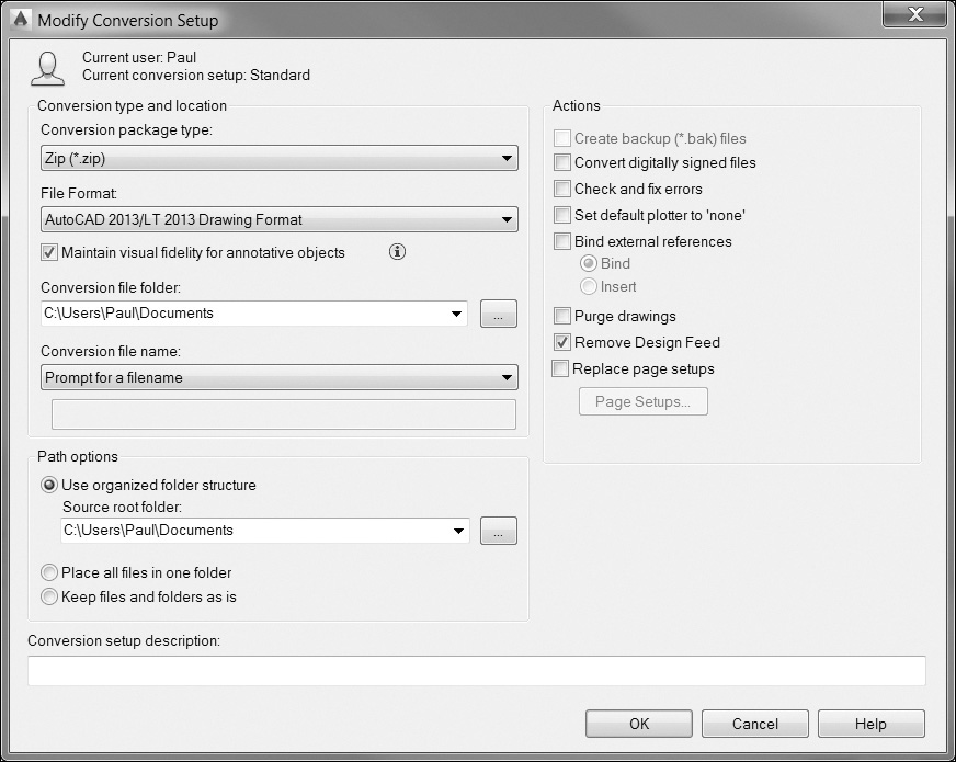
In the Conversion type and location area at the top of the dialog box, you select the desired file format to convert to, as well as whether to save the converted files in-place, to a specific folder, or to either a compressed zip file or a self-extracting .exe file.
The Actions area on the right side of the dialog box allows you to include one or more of the following actions to be performed during the conversion:
• Create backup (*.bak) files Backup files are automatically created during the conversion
• Convert digitally signed files Controls whether digitally signed drawings are converted
• Check and fix errors Drawings are checked for the presence of errors and automatically recovered if any errors are found
• Set default plotter to ‘none’ Changes the printer/plotter setting in the conversion package to None
• Bind external references Binds any xrefs as either a Bind or Insert type
• Purge drawings Automatically purges unreferenced information from drawings
• Remove Design Feed Automatically removes Design Feed information from drawings
• Replace page setups Replaces page setups with a page setup from another drawing
Object Linking and Embedding
Another way to share information between AutoCAD and other applications is to use object linking and embedding (OLE). OLE allows you to share information between two Windows applications. To use OLE, you need both the source and the destination applications that support OLE. The source application is the program used to create the document. The destination application is the program that is going to receive the source document. For example, if you were to embed an AutoCAD drawing in a Word document, AutoCAD is the source, and Word is the destination.
Note
Although the Windows OLE feature can use AutoCAD as either a source or a destination application, this chapter focuses primarily on placing OLE objects in AutoCAD drawings. Keep in mind that the behavior of data from other applications will vary from program to program. To link or embed AutoCAD drawings in other applications, refer to the documentation for that application for specifics on using OLE within that program.
Object Linking Versus Object Embedding
Both the linking and embedding processes insert information from one program’s document into another program’s document. The difference between linking and embedding involves how the information is stored. The difference is similar to the difference between inserting a block and creating an external reference.
Object Embedding
When an object is embedded into a document, that object is completely stored with the destination application. For example, if you created a Word document and then embedded it into an AutoCAD drawing, you would not need to save the Word file to a separate file. That Word document would exist entirely within the AutoCAD drawing. When the AutoCAD drawing is saved, the embedded Word document is saved along with it. This is similar to the relationship between an AutoCAD drawing and a block definition. Block definitions are defined and stored entirely within the AutoCAD drawing. The block does not need to exist as a separate drawing file.
Object Linking
When an object is linked, Windows simply creates a link between the source file and the destination file. Any changes made to the source document will be reflected in the destination document. If the source document is deleted, the link will be broken, and the OLE object will not be updated. This is similar to the relationship between an AutoCAD drawing and an xref. The drawing file does not store the entire xref, only a link to the referenced file. When the referenced file is updated, the AutoCAD drawing containing the xref is also updated.
Inserting OLE Objects
There are a number of ways to create and insert OLE objects within an AutoCAD drawing. The method you use will depend primarily on whether you want to link or embed the OLE object and how you want the OLE object to be displayed within the drawing.
Insert OLE Object |
|
Ribbon & Panel: |
Insert | Data |
|
|
Menu: |
Insert | OLE Object... |
Command Line: |
INSERTOBJ |
Command Alias: |
None |
The INSERTOBJ Command
The INSERTOBJ command allows you to create a linked or embedded object. When the command starts, AutoCAD displays the Insert Object dialog box (see Figure 18-16).
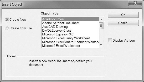
From this dialog box, you can choose whether you want to create a new OLE source document or use an existing file as the source document. Select the Create New button to create a new embedded document. Selecting this will only allow you to embed a new file. Once you select the type of file you wish to embed, Windows will launch that application with a new document for you to modify. Once you are done modifying the embedded object, select File|Update Drawing in the source application, and the embedded object will appear in your drawing. Because the object is now embedded in the AutoCAD drawing, you can close the source application.
Note
The Object Type: list in the Insert Object dialog box will vary depending on the software you have installed on your computer. Also, the exact method of updating the AutoCAD drawing may vary depending on the source application.
If you want to insert an existing document as an OLE object, select the Create from File button and then choose Browse... to select the source document. Once you select the source file, you can choose whether you want to link to the source file by putting a check in the Link box. Not checking the Link box will embed the source file in your drawing.
Paste |
|
Ribbon & Panel: |
Home | Clipboard
|
Menu: |
Edit | Paste |
Command Line: |
PASTECLIP |
Command Alias: |
Ctrl+V |

Placing a check in the Display As Icon box will display the OLE object as an icon within the drawing. This affects only how the OLE object is displayed in AutoCAD and does not affect the contents of the OLE object.
Using the Windows Clipboard
The Windows Clipboard feature can also be used to link and embed data from other applications. The Windows Clipboard provides a way to store data temporarily from most Windows programs. In most Windows applications, you can select data and choose Copy from the Edit pull-down menu or press <Ctrl>+C within that application. Once information is copied to the Windows Clipboard, it can be pasted into other locations within the same program or into other Windows applications.
Ribbon & Panel: |
Home | Clipboard
|
Menu: |
Edit | Paste Special... |
Command Line: |
PASTESPEC |
Command Alias: |
None |

The Windows Clipboard can be used to store information from within a file or to copy entire files or multiple files and folders.
When data are stored in the Windows Clipboard, they can be placed into an AutoCAD drawing using either the PASTECLIP or PASTESPEC command.
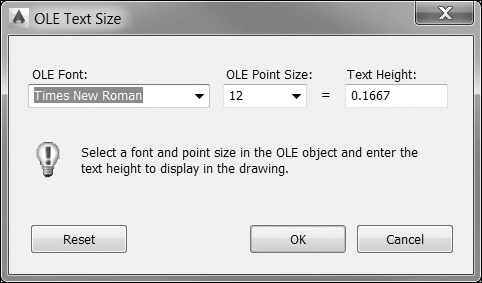
The PASTECLIP command will place the contents of the Clipboard as an embedded OLE object. When you start the PASTECLIP command, AutoCAD will prompt you for an insertion point. Depending on the type of data in the Clipboard, AutoCAD may display the OLE Text Size dialog box (see Figure 18-17). This dialog box allows you to control how Windows fonts are displayed within AutoCAD and allows you to convert the Windows text point size to AutoCAD text height.
Tip
You can also display the OLE Text Size dialog box by selecting an OLE object after it is inserted and right-clicking to display a shortcut menu with an OLE submenu with different OLE options including Text Size....
The PASTESPEC command gives you a little more control over how the Clipboard data are stored in AutoCAD. When you start the PASTESPEC command, AutoCAD displays the Paste Special dialog box (see Figure 18-18).

The PASTESPEC command allows you to place an OLE object as either a linked or embedded object. It also gives you the ability to convert the Clipboard contents to AutoCAD entities. The types of entities created depend on the type of data in the Clipboard. AutoCAD will automatically convert the Clipboard data to the most appropriate AutoCAD object. For example, Excel spreadsheet data are converted to an AutoCAD table, Word data are converted to AutoCAD text, raster image data are converted to AutoCAD image overlays, etc.
Drag and Drop
Another feature of Windows is the ability to drag and drop data between Windows applications. Drag and drop involves selecting data in the source application and, while holding your left mouse button down, dragging the data onto your AutoCAD drawing. This can take a little practice and preplanning because both applications must be visible and accessible.
Drag and drop works the same as PASTECLIP; the only difference is that drag and drop bypasses the Windows Clipboard.
Editing OLE Objects
The nature of OLE objects is that they are edited in their source application. Double-clicking an OLE object will launch the source application with the OLE data. You can make changes to the source data and then either close the source application or, in most applications, choose Close and Return to Drawing from the File menu in the source application.
OLE Links |
|
Ribbon & Panel: |
None
|
Menu: |
Edit | OLE Links |
Command Line: |
OLELINKS |
Command Alias: |
None |

Managing Linked Objects
Linked objects, because they rely on the coordination of multiple files, require a little more attention than embedded objects. The location of the linked file is critical to updating and maintaining the information in the OLE object. The way in which you want the information updated and the ability to terminate a link are also part of maintaining an OLE linked object. The OLELINKS command allows you to manage linked OLE objects from within AutoCAD.
The OLELINKS command works only if you have linked OLE objects in your AutoCAD drawing. When you start the OLELINKS command, AutoCAD displays the Links dialog box (see Figure 18-19). The Update Now button will refresh the OLE object from the source file. The Open Source button will open the source file and allow you to make changes. The Change Source... button allows you to specify a different source file for the OLE object. When you change the source file, the new source file must be the same type of file as the original source file. The Break Link button will terminate the link between AutoCAD and the source file and turn the linked object into an embedded object.
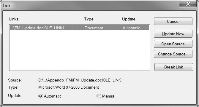
At the bottom of the Links dialog box are two buttons that allow you to control how the OLE objects are updated. Choosing Automatic causes AutoCAD to update the OLE object whenever the source file changes. Choosing Manual tells AutoCAD not to update the OLE object until you choose the Update Now button.
Plot Quality
OLE objects are treated as raster objects when a raster plotter is used. Because large, high-resolution, color-rich rasters can be expensive to plot, you can set the OLEQUALITY system variable to control how each OLE object is plotted. There are four possible settings: 0 (Monochrome), 1 (Low Quality), 2 (High Quality), and 3 (Automatically Select). The default setting, Automatically Select, assigns a plot-quality level based on the type of object. The higher the plot-quality setting, the more time and memory are used to plot. The OLEQUALITY variable can be applied separately to each OLE object in the drawing.
Controlling the Visibility of OLE Objects
While working on a drawing, you may want to suppress the display or plotting of OLE objects. The OLEHIDE system variable allows you to control the visibility and plotting of OLE objects in model space, paper space, or both. The default setting is 0, which displays and plots all OLE objects in both model and paper space. Setting OLEHIDE to 1 displays and plots OLE objects in paper space only. Setting OLEHIDE to 2 displays and plots OLE objects in model space only. Setting OLEHIDE to 3 suppresses the display and plotting of all OLE objects in both model and paper space. The OLEHIDE variable applies globally to all OLE objects in a drawing.
OLEFRAME System Variable
When OLE objects are placed in AutoCAD, they behave like other AutoCAD objects in that they have default properties, such as layer color and linetype, associated with them. Like raster image overlays, these properties apply to the frame surrounding the OLE objects. The OLEFRAME system variable controls the display and plotting of the OLE object frame. Setting OLEFRAME to 0 turns off the OLE frame, and it will not be displayed or plotted. Setting OLEFRAME to 1 displays the OLE frame both on screen and in plots. Setting OLEFRAME to 2 displays the OLE frame in the display but suppresses it in plots. The OLEFRAME variable applies globally to all OLE objects in a drawing.
OLE Properties
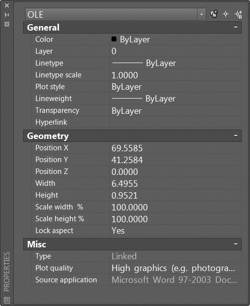
As stated earlier, OLE objects behave similarly to other objects in a drawing. They can be moved, copied, resized, etc. The Properties palette (see Figure 18-20) displays information specific to OLE objects, such as the location and the height and width scale of the OLE object. You can also control the plot quality of the OLE object.
Action Recorder
The Action Recorder tool allows you to automate repetitive tasks by recording the AutoCAD commands, inputs, and options you enter as an action macro that you, or anyone else, can replay later. If you find yourself doing the same series of steps over and over again, the Action Recorder can help by recording them so that the next time you need to do the same thing, all you have to do is press the Play button. The Play button and all the other Action Recorder tools and features are located on the Action Recorder panel on the Manage tab of the ribbon shown in Figure 18-21.

Note
There are certain actions that cannot be recorded—specifically, file operation commands such as OPEN and CLOSE, as well as any type of grip editing. Although it is possible to display a dialog box, it is not possible to track and record your actions once it is displayed. Additionally, the Quick Properties palette is not recognized, and certain tool palette commands cannot be recorded.
To use the Action Recorder you simply press the Record button, step through the series of commands that you would normally go through to complete a task, and push the Stop button when you are done. The Action Recorder can record actions entered via the command line window, ribbon panels, menus, the Layer Properties Manager, the Properties palette, tool palettes, and even toolbars. While recording an action macro, the Red Recording Circle icon is displayed near the crosshairs to indicate that the Action Recorder is running and any commands and input are being recorded.
Tip
Many commands have an alternate command line–only version that can be accessed by prefixing the command with a hyphen (-) that allows you to work around the Action Recorder’s inability to record dialog box actions. For instance, whereas the HATCH command displays the Hatch and Gradient dialog box, which cannot be recorded, the -HATCH command allows you to place hatches by entering all the command options via the keyboard so that the Action Recorder can record them.
When you press the Stop button, the Action Macro dialog box shown in Figure 18-22 is displayed so you can enter a command name for the macro.
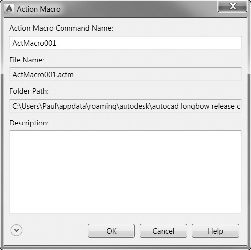
All the actions entered are saved to an action macro file with an .ACTM file extension. The default macro and file name provided is ActMacro001, where the 3-digit suffix is incremented each time. It is suggested that you enter a more descriptive name that better indicates the nature of the macro.
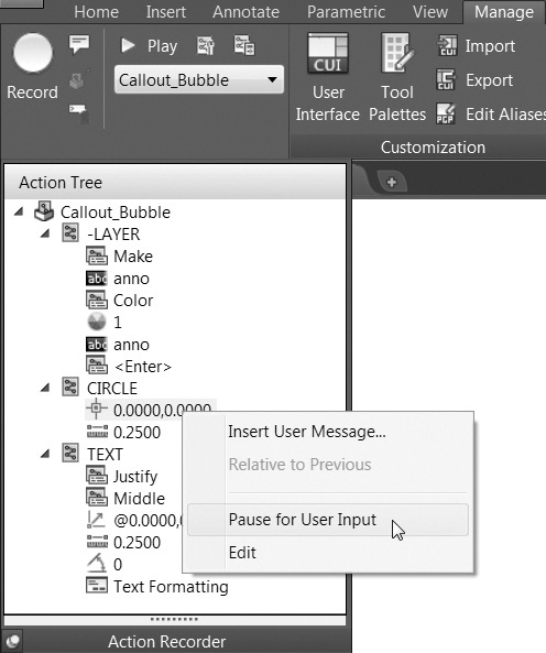
The best thing about action macros is that, after you are done recording a macro, you can go back and customize it by adding your own text messages and pauses for user input by right-clicking on an action in the Action Tree window and using the shortcut menu shown in Figure 18-23.
Note
There are a few limitations when naming an action macro. An action macro cannot have the same name as an AutoCAD command. For instance, you cannot create a macro named LINE. It is also not possible to use spaces or special characters. It is suggested you substitute a dash (-) or an underscore (_) when a space is required.
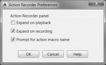
The Preferences button on the Action Recorder panel displays the Action Recorder Preferences dialog box shown in Figure 18-24, which allows you to control whether the Action Recorder panel expands when recording or playing back an action macro, and if you are prompted to provide a command name for the action macro when you press the Stop button and recording is stopped.
Tip
By default, action macro files are stored in the folder specified in the Actions Recording File Location setting under Action Recorder Settings on the Files tab of the Options dialog box. The Additional Actions Reading File Locations setting allows you to share action macro files in a network location so multiple people on different computers can access and run them.
Measure Tools
The Measure tools located on the Utilities panel on the Home tab of the ribbon shown in Figure 18-25 allow you to measure the distance, radius, angle, area, or volume of a selected object or sequence of points.
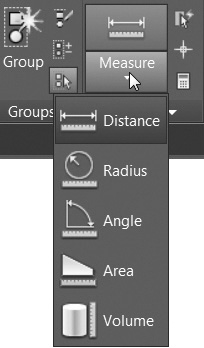
The Distance tool allows you to measure the distance between two points. After you select two points, AutoCAD displays the distance, delta x, delta y, and angle directly on your screen and at the AutoCAD command line window. The Multiple option allows you to continue picking points and display a cumulative distance.
The Radius tool allows you to measure the radius of a selected arc or circle.
The Angle tool allows you to measure the angle of a selected arc, circle, or line. The default Specify vertex option allows you to pick three points starting with the vertex.
The Area tool allows you to select objects or pick points and display the included area. The Add and Subtract options allow you to calculate cumulative areas.
The Volume tool allows you to calculate an area using techniques similar to the Area tool and then specify a height to determine the volume. It is also possible to display the volume of selected solids or regions.
QuickCalc Calculator
The QuickCalc calculator shown in Figure 18-26 provides all of the functionality of a traditional desktop calculator, or even the Windows calculator, plus a host of unique features that are specific to AutoCAD.
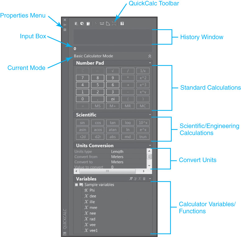
In addition to standard mathematical calculations, the QuickCalc calculator provides the ability to select points, distances, and angles in your drawing; perform scientific and engineering calculations; convert units; and store/retrieve variables. Some of the different QuickCalc calculator capabilities and features include:
• Running History window that allows you to see, and even reevaluate, previously entered expressions and calculations
• Ability to share calculations with the Properties palette and automatically update/modify object properties in your drawing
• Perform complex mathematical and trigonometric calculations
• Convert between different unit systems using AutoCAD data values
• Perform geometric calculations based on specific object types
• Copy and paste values/expressions to and from the command prompt
• Compute both feet/inch and fractional values in stacked or decimal format
• Define, store, and retrieve built-in and user-defined calculator variables
Note
The Windows calculator can typically be found in the Accessories folder if you go to the Windows Start button and select All Programs.
Tip
The QuickCalc calculator is an AutoCAD palette so it shares many of the interface features you should now be familiar with. It can be easily resized and placed anywhere on your screen. In addition, it is possible to turn on its Auto-hide feature so the palette collapses when not in use. These and other features can be easily accessed via the palette Properties menu that is displayed when you select the Properties button on the palette title bar.
Using QuickCalc
There are a few different ways to use the QuickCalc calculator in AutoCAD:
• Directly, by displaying the QuickCalc palette using one of the following methods:
• Select QuickCalc from the Palettes panel on the View tab of the ribbon.
• Right-click with your mouse and select QuickCalc from the shortcut menu.
• Enter the command QUICKCALC or its alias QC at the command prompt.
• Interacting with the Properties palette
• Within a command from a shortcut menu or via the command prompt
The first method is pretty self-explanatory. When you interact with QuickCalc directly, you are using it basically as a regular calculator, similar to the calculator that comes with Windows. You can copy and paste numerical values back and forth between AutoCAD and the calculator using the Windows Clipboard, but nothing that happens in QuickCalc affects your drawing.
You interact with the Properties palette by selecting the QuickCalc button that is displayed next to the property value you are working with. Clicking on QuickCalc displays the current property value in QuickCalc so you can calculate a value. After you are done calculating a value, you can transfer the result back to the Properties palette by selecting the Apply button. The property is updated, and any associated object(s) are changed in the drawing.
When a command is active, you can access QuickCalc either by right-clicking to display the shortcut menu and select QuickCalc or by entering QUICKCALC or QC at the command prompt and preceding it with an apostrophe (’). Using the apostrophe (’) prefix allows QUICKCALC to run transparently within the command. If you omit the prefix, you will receive an error. After you are done calculating a value, you can transfer the result back to the active command by selecting the Apply button. Calculations that you transfer back to the command will update the drawing accordingly.
Note
If you are using QuickCalc within a command to calculate a value for direct distance entry, you must first position the cursor to determine the desired direction and then press the <Enter> key.
Tip
The current QuickCalc mode indicating whether you started QuickCalc directly (Basic Calculator Mode), via the Properties palette (Property Calculation), or within a command (Active Command) is always displayed directly below the Input box, as shown in Figure 18-26.
Entering and Evaluating Expressions
Expressions are entered in the Input box shown in Figure 18-26 via the keyboard, the QuickCalc number pad, or a combination of both. QuickCalc evaluates expressions according to the standard mathematical rules of precedence:
• Expressions in parentheses are evaluated first, starting with the innermost set of parentheses and working out.
• Mathematical operators are processed in standard order (exponents, multiply/divide, add/subtract).
• Operators of equal precedence are evaluated from left to right.
You can either press the <Enter> key on your keyboard or click on the equal sign (=) on the QuickCalc number pad to evaluate an expression entered in the Input box.
All expressions that you enter are stored in the History window at the top of the palette so that you can review and retrieve them for reevaluation using different input values if you want. The right-click menu in the History window provides the ability to paste expressions and their values back to the Input box or to the AutoCAD command prompt.
If units are currently set to Architectural, the calculator displays the results of calculations entered in imperial units in the architectural format and rounds them to the current linear precision set in the drawing. The results for all other calculations display in decimal format with full precision.
It is possible to enter feet (′) and inch (″) units anytime in the Input box, even if the units are not currently set to Architectural or Engineering in the drawing. Unlike when entering distances at the command prompt, you can separate feet, inches, and fractional inches with a dash, a space, or nothing. The following are all valid feet-inch formatted values:
4′ or 48″∂
4′-7″ or 4′ 7″ or 4′7″∂
4′-1/2″ or 4′ 1/2″ or 4′1/2″∂
4′-7-1/2″ or 4′ 7-1/2″ or 4′7-1/2″∂
4′-7 1/2″ or 4′ 7 1/2″ or 4′7 1/2″∂
Similar to entering inches at the command prompt, in QuickCalc, you have the option of either entering double quotes (”) when specifying inches or simply omitting them.
Note
If you are using imperial units, QuickCalc interprets the dash (-) as a unit separator rather than a subtraction operator. To indicate subtraction, you must include at least one space before or after the minus sign in your expressions.
Tip
You can use QuickCalc to calculate square feet and cubic feet using the following abbreviations:
sq. ft. or sq ft
cu. ft. or cu ft
The QuickCalc Toolbar
The toolbar at the top of the QuickCalc palette shown in Figure 18-27 provides a variety of useful tools and functions.

The different tools and their descriptions are as follows:
• Clear Clears the Input box similar to selecting C on the number pad
• Clear History Clears the History area
• Paste Value to Command Line Pastes the value currently displayed in the Input box to the command prompt. When QuickCalc is used transparently within a command, this button is removed from the toolbar and replaced by the Apply button at the bottom of the calculator so you can apply results directly to the active command
• Get Coordinates Returns the coordinate value of a point selected in the drawing
• Distance Between Two Points Calculates the distance between two points selected in the drawing. The distance is always returned as a unitless decimal value regardless of the current unit settings
• Angle of Line Defined by Two Points Calculates the angle of the line defined by two points selected in the drawing
• Intersection of Two Lines Defined by Four Points Calculates the intersection of two lines defined by four points selected in the drawing
As you can see, a number of the tools interact with your AutoCAD drawing so that you can retrieve drawing information such as point coordinates, distances, and angles and input them directly into QuickCalc. You can then use QuickCalc to perform complex calculations using the drawing data and then, if you want, you can send the results back to AutoCAD by using copy and paste techniques or by using the Apply button, depending on how you started QuickCalc.
Converting Units
The Units Conversion section of the QuickCalc calculator shown in Figure 18-26 allows you to quickly convert length, area, volume, and angular values between different unit systems. The list of units in the Convert from and Convert to drop-down lists is determined by the unit type currently selected at the top in the Units type drop-down list.
Note
You should always enter decimal values without any units in the Value to convert box.
The number in the Value to convert box automatically displays the current value in the Input box, but you can simply overwrite it if you want to convert a different value. The result of the units conversion is instantly displayed in the Converted value box. You can copy the result to the Input box by clicking the QuickCalc icon on the right side of the box.
variable: User-defined unit of storage that may assume any given value or set of values.
Calculator Variables
The Variables section of the QuickCalc calculator shown in Figure 18-28 provides the ability to define, store, and retrieve calculator variables.
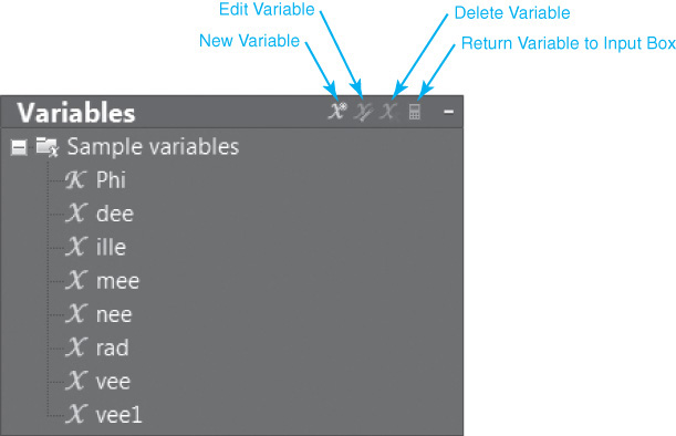
Variables can be either constant values (coordinates, real numbers, or integers) or functions. When you hover your mouse over a variable, a tooltip displays with the variable’s current value, type, and description. Double-clicking on a variable places its value in the QuickCalc Input box. The toolbar at the top of the Variables section and a right-click menu provide the following capabilities:
• Create a new variable or category
• Edit an existing variable
• Rename a variable
• Delete a variable
• Return variable value to Input box
AutoCAD provides a number of sample variables and functions. Most of these are expressions that combine the AutoCAD CAL functions with the Endpoint object snap mode. The following table provides a list of the sample variables/functions:
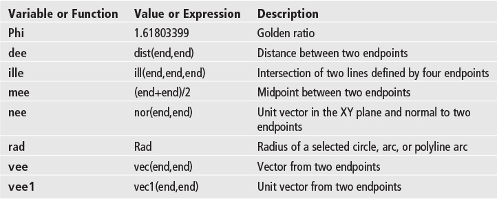
You can either modify the sample variables/functions or create your own.
Creating and Editing Calculator Variables
You create and edit calculator variables using the Variable Definition dialog box shown in Figure 18-29.

The following rules apply when defining new variables:
• Constants Expressions entered in the Value or expression: text box are evaluated before they are stored. Variables that are defined as constants are accessible in other drawings and between AutoCAD sessions.
• Functions Expressions entered in the Value or expression: text box are stored as text. Functions are evaluated when they are used in the QuickCalc Input box.
Note
The CAL command is the original command line version of the QuickCalc calculator that is typically referred to as the geometry calculator. The CAL functions allow you to evaluate point, real, or integer expressions that incorporate existing AutoCAD drawing geometry and the object snap functions. For more information about the CAL command, please consult the AutoCAD Help.
Deleting Duplicate Objects
The Delete Duplicate Objects tool helps you clean up your drawings by removing duplicate or unnecessary drawing objects (lines, arcs, polylines) so that you can enhance and preserve the data integrity of your drawings.
Delete Duplicate Objects |
|
Ribbon & Panel: |
Home | Modify
|
Menu: |
Modify |
Command Line: |
OVERKILL |
Command Alias: |
None |

Note
The Delete Duplicate Objects tool can be set to combine partially overlapping or contiguous objects.
The first thing that you do after starting the Delete Duplicate Objects tool is select the objects in the drawing that you want to process.
Tip
You can type All<Enter> to quickly select everything in the drawing.
After the desired objects are selected and you press <Enter> to accept the selection set, the Delete Duplicate Objects dialog box shown in Figure 18-30 is displayed so you can refine the deletion process.
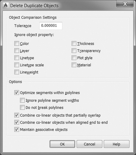
The Delete Duplicate Objects dialog box allows you to control the following settings and options:
• Tolerance Controls the precision with which the OVERKILL command makes numeric comparisons
• Ignore object property Determines which object properties are ignored during comparison
• Optimize segments within polylines Individual line and arc segments within selected polylines are examined so that duplicate vertices and segments are removed
• Combine co-linear objects that partially overlap Overlapping objects are combined into single objects
• Combine co-linear objects when aligned end to end Objects that have common endpoints are combined into single objects
• Maintain associative objects Associative objects are not deleted or modified
Web-Based Collaboration Tools
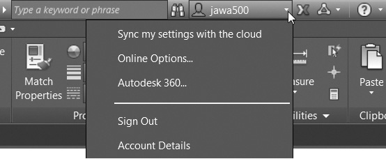
AutoCAD is integrated directly with the Internet and the Autodesk 360 web and mobile applications. Autodesk 360 lets you view, edit, and share drawings using the web or a mobile device. The Autodesk 360 options are located on the Autodesk 360 drop-down menu on the InfoCenter toolbar shown in Figure 18-31.
Autodesk 360
Autodesk® 360 provides web-enabled, typically referred to as cloud-based, features, services, and other products that allow you to design, visualize, simulate, and share your work with others anytime, anywhere via the Internet. Features include:
• Storage Store your design files online through an Autodesk 360 account that allows you to access them anytime, anywhere
• Viewing Allow others to view your design files—even if they do not have AutoCAD. Users can view and edit 2D and 3D design files through a web browser or via a mobile device using Autodesk 360
• Collaboration and Sharing Share files, keep track of file updates, and invite others to comment on designs in the Autodesk 360 collaboration workspace
You can quickly sign into your Autodesk 360 account and access many of the Autodesk 360 tools and options via the AutoDesk 360 drop-down menu on the InfoCenter toolbar as shown in Figure 18-31.
The first time you access Autodesk 360, you have the opportunity to specify default cloud settings to control when your design data and custom settings are synced with the cloud. When you upload drawings directly from AutoCAD to Autodesk 360, external references and other dependent files are automatically included with the upload.
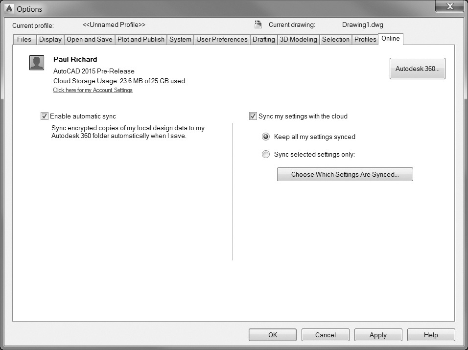
You can also choose to automatically sync your program appearance, profiles, workspaces, options, and support files so that you can restore them on any computer. You can modify the default cloud settings by selecting Online Options... on the drop-down menu on the InfoCenter toolbar shown in Figure 18-31, which displays the Online tab of the AutoCAD Options dialog box shown in Figure 18-32.
The Autodesk 360 Tab
The Autodesk 360 tools are located on the Autodesk 360 tab of the ribbon shown in Figure 18-33.
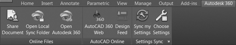
The Autodesk 360 tab tools are explained in the following sections.
The Share Document Tool
Use the Share Document tool to share your current drawing with other users. If the current drawing is only saved locally, a copy of the drawing is uploaded to the cloud and shared. It is possible to control the access level of shared documents.
The Open Local Sync Folder Tool
The Open Local Sync Folder tool opens your local Autodesk 360 folder in Windows Explorer.
The Open Autodesk 360 Tool
The Open Autodesk 360 tool opens your Autodesk 360 documents list and folders in a browser as shown in Figure 18-34. If you are not already logged in, you’re prompted to do so.
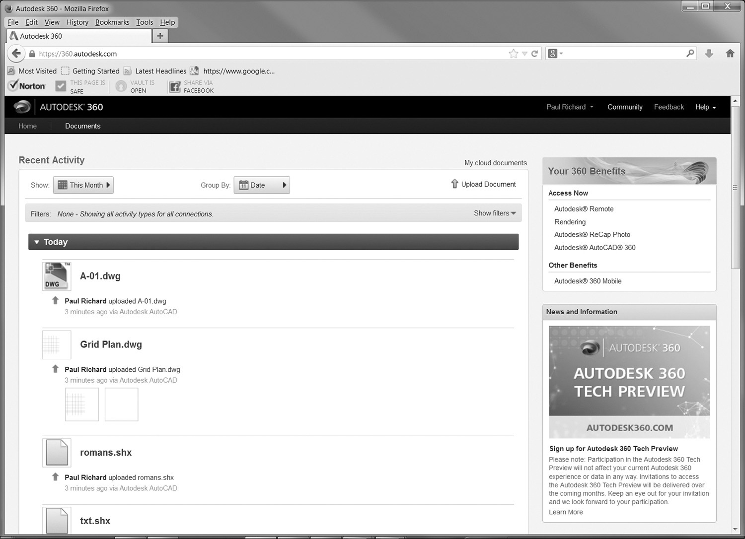
Your Autodesk 360 documents are also available from many of the common Select File dialog boxes throughout AutoCAD such as Save As and Open. For example, when you open, save, or attach a file, you can access Autodesk 360 directly from the Places list on the left side of the dialog box.
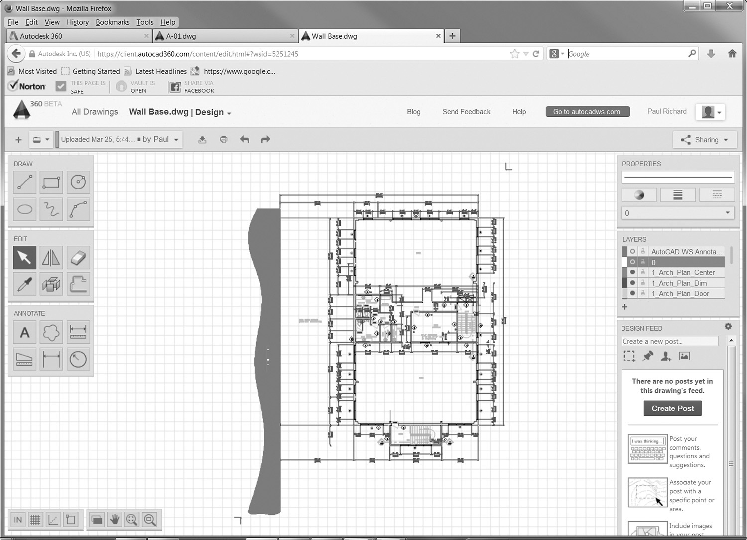
Once a drawing has been uploaded, you can edit it online using Autodesk 360, the browser-based drawing editor provided by Autodesk shown in Figure 18-35.
The AutoCAD 360 Web Tool
The AutoCAD 360 Web tool launches the Autodesk 360 website in your default browser.
The Design Feed Tool
The Design Feed tool toggles on and off the Design Feed palette shown in Figure 18-36.
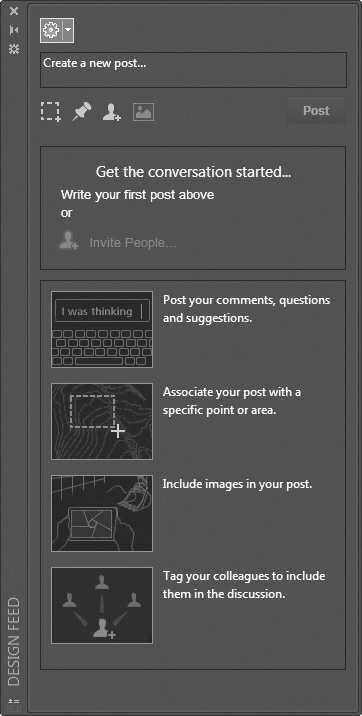
The Design Feed palette allows you to add messages and images to a drawing and share them online through Autodesk 360. The Design Feed posts are available in a drawing whether it is opened on the local computer, on the web, or via a mobile device.
Comments can be associated with a location or area within the drawing with a corresponding bubble. When you select a comment in Design Feed, AutoCAD zooms to the corresponding part of the drawing. If you select a bubble in the drawing, the corresponding comment is also highlighted in Design Feed. The Design Feed Settings drop-down menu at the top of the Design Feed palette provides control of the bubble display.
You can tag others to notify them of your posts, which then get sent to them by email and also appear within Design Feed.
After you finish creating a post, the updated Design Feed data and associated images are saved to Autodesk 360. Then you or anyone else that has been authorized to view the drawing can see the associated posts. When the comment and its replies are no longer needed, you can resolve the thread and hide it in the Design Feed palette.
The Sync My Settings Tool
The Sync my Settings tool enables you to start and stop syncing of your custom settings. If you stop syncing your custom settings, your online settings are preserved but no longer updated.
If you choose to sync your settings, AutoCAD compares your local settings with your cloud settings and prompts you to choose whether you want to use your local settings, in which case it will upload them to the cloud, or your online settings, in which case it will download them from the cloud.
Bubble notifications indicate when settings are being uploaded to or downloaded from the cloud.
The Choose Settings Tool
Use the Choose Settings tool to specify which settings to include in the customization sync:
• The Options setting includes almost all the controls in the Options dialog box.
• The Customization Files setting includes custom menu files, workspace files, and more (.cuix, .aws).
• The Printer support files setting includes copies of printer support files (.pc3, .ctb, and .stb).
• The Custom hatch patterns setting includes your custom hatch pattern files (.pat).
• The Tool Palettes setting includes tool palette files and groups (.atc, .xtp).
• The Drawing template files setting includes your drawing templates (.dwt).
• The Custom fonts, shapes, and linetypes setting requires that AutoCAD be restarted.
When you make changes to your customization settings with synchronization enabled, a bubble notification in the upper right corner notifies you that the changes are being uploaded.
When you sign out of Autodesk 360, a dialog box asks you to choose whether you want to keep your custom settings or restore the previous settings.
Chapter Summary
This chapter explored additional drawing management techniques that include recovering and fixing corrupt files and changing settings in AutoCAD to create backup files. Remember that AutoCAD drawings can be shared with other CAD programs and viewed in other software applications. In turn, other CAD and Windows-based files can be translated into AutoCAD. Sharing data from one software application to another is cost efficient, productive, and becoming commonplace in the design industry. AutoCAD has internal tools to assist with these file translations. As with most Windows software, AutoCAD provides all the object linking and embedding tools such as Copy, Cut, and Paste, as well as ways to enhance OLE objects with system variables that control display, plotting, and editing options. Automating repetitive tasks using the Action Recorder tool saves an enormous amount of time and helps to promote standards. The Measure tools allow you to quickly check your work and that of others, as well as instantly ascertain areas and volumes. The QuickCalc calculator is integrated into AutoCAD so you can perform complex mathematical expressions and convert units, then apply the results directly in your drawing. The Delete Duplicate Objects tool not only helps you to maintain data integrity in your drawings but also helps reduce file sizes. Finally, the web-based collaboration tools provided by Autodesk 360 allow you to share and update your drawing files in real time on the web and on mobile devices so that everyone on the team always has access to the latest and greatest information wherever he or she is located.
Chapter Test Questions
Multiple Choice
Circle the correct answer.
1. The PURGE command can remove unused:
a. Layers
b. Linetypes
c. Blocks
d. All of the above
2. The EXPORT command supports the following file types:
a. WMF, JPG, EPS, DXX, BMP, DWG, 3DS
b. WMF, SAT, EPS, DXX, BMP, 3DS, DWG
c. JPG, PNG, DXX, BMP, DXX, EPS, SAT
d. None of the above
3. The command that saves and exports an AutoCAD object into a drawing file is:
a. WBLOCK
b. WMFOUT
c. JPGOUT
d. DWGOUT
4. The backup file extension is:
a. AC$
b. BAC
c. SV$
d. BAK
5. A DXF file can be created by:
a. Pasting a DWG file into Word
b. Using the SAVE or SAVEAS command
c. Using the XREF command
d. None of the above
6. A source application file:
a. Is where an object is linked
b. Can never be changed or edited
c. Is the same as a destination file
d. None of the above
7. Dragging and dropping objects is the same as:
a. Embedding and linking
b. Copying and pasting
c. Cutting and pasting
d. All of the above
8. An AutoCAD file with linked objects:
a. Can be automatically updated if there are changes to the source file
b. Tends to be smaller in file size than files with embedded objects
c. Must be updated if either the source or the destination file is moved to another drive or directory
d. All of the above
9. An embedded object can be changed or edited in an AutoCAD file:
a. By right-clicking on the object and selecting Edit
b. By double-clicking on the object to bring up the source application
c. By deleting the object, re-creating an updated version in the source file, and bringing it back into AutoCAD through the Clipboard
d. Is not allowed
10. The QuickCalc calculator can be displayed by:
a. Right-clicking and selecting it from the shortcut menu
b. Selecting it from the Palettes panel on the View tab of the ribbon
c. Entering QC at the command prompt
d. All of the above
Matching
Write the number of the correct answer on the line.
1. True or False: The RECOVER command can be used on open drawings.
2. True or False: The AUDIT command can be used on closed drawings.
3. True or False: The Drawing Recovery Manager can restore an unsaved drawing file.
4. True or False: The PURGE command is used to erase unused named objects.
5. True or False: The INSERTOBJ command can be used to create a table from scratch in Word and link it into AutoCAD.
6. True or False: The OLE Links dialog box is used to update, change, or break a linked object in AutoCAD.
7. True or False: The OLEFRAME system variable when set to 2 will display a frame around an OLE object on the screen and a plot.
8. True or False: The Action Recorder can record selections made in a dialog box.
9. True or False: The BMP export file is a raster image.
10. True or False: OLE also means object linking and editing.