
Chapter 15. Plotting and Publishing
• Plot from both model space and paper space
• Manage page setups using plot styles
• Control the final look of a plotted sheet
• Select, add, and configure various plotting devices
• Create electronic plot files including DWF, PDF, and other raster file formats
• View and mark up DWF files in the Autodesk Design Review application
Introduction
In most cases, the purpose of creating AutoCAD drawings is to create a set of printed hard-copy drawings. In AutoCAD, this process is called plotting. In Chapter 14, we looked at how to create and manage paper space layouts, which (among other things) allow you to define the default settings for a plot. In this chapter, we examine various ways of outputting drawings, including how to plot from model space and how to plot to various file formats.
plotting: The process of printing a drawing in AutoCAD.
Plot |
|
Ribbon & Panel: |
Output | Plot
|
Menu: |
File | Plot... |
Command Line: |
PLOT/PRINT |
Command Alias: |
CTRL+P |

Page Setups and Plotting
In Chapter 14, we looked at how to create a page setup using the PAGESETUP command. Page setups are simply collections of plot settings that have a name assigned to them. When creating a page setup, you specify the default printer/plotter, the default paper size, and other default output options. Each drawing space (model space and each paper space layout) has a default page setup assigned to it that contains all the default plot settings for that drawing space.
In the early days of AutoCAD, drawings were typically output to pen plotters, which would create hard-copy prints by physically grabbing a pen and moving it around a piece of paper or Mylar. Although these types of plotters are rarely used today, the terminology has remained. Today, the terms print and plot are synonymous in AutoCAD.
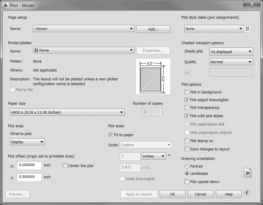
Plotting is done with the PLOT command. When you start the PLOT command, AutoCAD looks at the current page setup and displays those settings in the Plot dialog box (see Figure 15-1).
Tip
The quickest way to start the PLOT command is by selecting the Plot . . . button on the Quick Access toolbar, which is always displayed on the top left of the AutoCAD window.
The Plot dialog box has the same settings as the Page Setup dialog box and allows you to make any final adjustments to your plot settings before outputting your drawing. The Plot dialog box also has additional controls that allow you to create and modify page setups.
Note
The main difference between the Plot dialog box and the Page Setup dialog box is that any changes are discarded when you select OK in the Plot dialog box unless you select the Apply to Layout button.
To create a plot using the default page setup values, you can simply start the PLOT command and choose OK. However, before you commit your drawing to paper, it’s a good idea to check over your default settings and preview your plot.
Previewing Your Plot
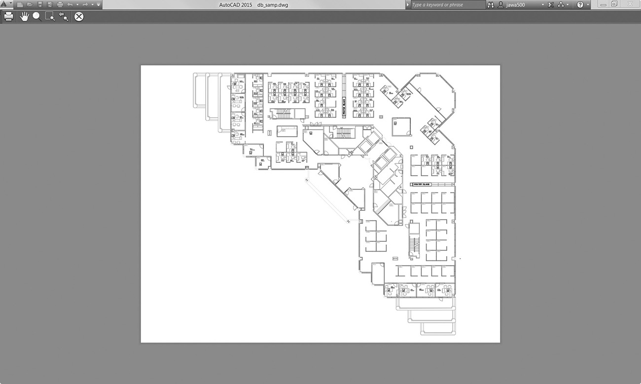
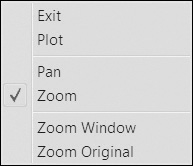
The Preview... button in the Plot dialog box allows you to see a preview of the final output before you commit it to paper. When you select the Preview... button, AutoCAD switches to plot preview mode (see Figure 15-2). In preview mode, the AutoCAD toolbars and pull-down menus are replaced with the Preview toolbar. These tools allow you to zoom in on and pan around the drawing to inspect it before you send it to the printer. If you are satisfied with the preview, you can choose the Plot button to send the drawing to the printer. Otherwise, you can choose Cancel to return to the Plot dialog box. The tools available in the Preview toolbar are also available in the Preview Mode right-click menu (see Figure 15-3).
Preview |
|
Ribbon & Panel: |
Output | Plot
|
Menu: |
File | Plot Preview |
Command Line: |
PREVIEW |
Command Alias: |
None |

The PREVIEW Command
If you’re confident in your plot settings, you can go directly to a plot preview with the PREVIEW command. The PREVIEW command bypasses the PLOT command and goes directly to plot preview mode. If you’re satisfied with the plot preview, you can choose the Plot button and output your drawing. However, if you need to make changes, choosing Cancel will return you to your drawing. You then have to use the PLOT or PAGESETUP command to make changes to your default plot settings.
Plotting from Model Space
The process of plotting is the same whether you plot from model space or paper space. However, there are some things to keep in mind when plotting from model space, particularly with regard to plot scale.
Specifying the Plot Area
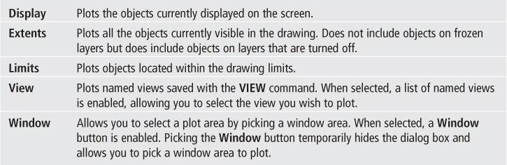
When plotting a paper space layout, you will typically plot the entire layout. Selecting the Layout option in the What to plot: list tells AutoCAD to plot the area defined in the paper space layout. When plotting from model space, the Layout option is not available, and you must choose a specific area to plot. The What to plot: drop-down list allows you to specify a number of different plot areas. The options are described below.
Setting the Plot Scale
Because a paper space layout represents an actual piece of paper, the plot scale of a paper space layout is typically 1:1. The plot scale of your model is set within each viewport.
However, model space represents the actual full-size version of your design. When you plot from model space, you typically need to adjust the plot scale so that the full-size version of your design will fit on a piece of paper.
The Plot scale area of the Plot dialog box allows you to set the drawing scale. When selected, the Fit to paper check box will examine the specified plot area and scale it to fit the specified paper size. The calculated scale will appear grayed out in the Scale area.
To plot at a specific scale, remove the check from the Fit to paper box to enable the Scale area. Once enabled, you can specify a plot scale by selecting it from the Scale list or by selecting Custom from the list and specifying a custom scale. Custom scales are entered as plotted (paper) units in either inches or millimeters (mm) and their equivalent drawing units. For example, to specify a scale of 1/4″ = 1′-0″, you could either choose it from the Scale list or choose Custom and specify .25 inch = 12 units, or 1 inch = 48 units.
Tip
You can add to and modify the list of available plot scales with the SCALELISTEDIT command. See page 584 in Chapter 14 for more information about the SCALELISTEDIT command.
Setting the Plot Offset
The Plot offset area allows you to position your plot area on your paper. When set to X: 0 and Y: 0, AutoCAD will place the specified plot area of your drawing at the lower left corner of the printable area of your paper. Recall from Chapter 14 that the printable area is the actual physical area that can be printed for a specified plotting device and paper size. This area varies with the printer and paper size you select.
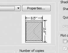
By changing the X and Y offset values, you can reposition the drawing plot area on the paper. If your plot area goes outside the printable area, AutoCAD will warn you by showing a red line in the preview area of the Plot dialog box (see Figure 15-4).
Tip
You can change the plot offset to be relative to the edge of the paper instead of the printable area on the Plot and Publish tab of the Options dialog box.
The Center the plot check box will compare the printable area of your paper to the plot area of your drawing and calculate the appropriate X and Y offset values to center the plot area in the printable area of your paper.
Exercise 15-1 Plotting from Model Space
![]() Open drawing db_samp located in the student data files.
Open drawing db_samp located in the student data files.
To access student data files, go to www.pearsondesigncentral.com.
![]() Start the PLOT command to display the Plot dialog box.
Start the PLOT command to display the Plot dialog box.
![]() Select the DWF6 ePlot.pc3 printer, and then select the ARCH D (36.00 × 24.00 Inches) paper size.
Select the DWF6 ePlot.pc3 printer, and then select the ARCH D (36.00 × 24.00 Inches) paper size.
![]() Select Extents from the What to plot: list.
Select Extents from the What to plot: list.
![]() Remove the check from the Fit to paper box, and choose 3/32″ = 1′-0″ from the Scale list.
Remove the check from the Fit to paper box, and choose 3/32″ = 1′-0″ from the Scale list.
![]() Choose Center the plot option in the Plot offset area.
Choose Center the plot option in the Plot offset area.
![]() Select the Preview... button.
Select the Preview... button.
![]() AutoCAD will display the plot preview shown earlier in Figure 15-2. You can zoom and pan to examine the plot preview. When done, choose the Close Preview Window button to return to the Plot dialog box.
AutoCAD will display the plot preview shown earlier in Figure 15-2. You can zoom and pan to examine the plot preview. When done, choose the Close Preview Window button to return to the Plot dialog box.
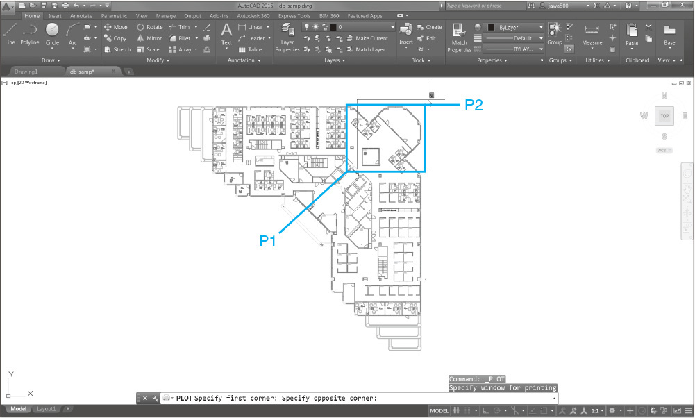
![]() In the What to plot: list, choose Window. AutoCAD will close the dialog box and prompt you to Specify first corner:.
In the What to plot: list, choose Window. AutoCAD will close the dialog box and prompt you to Specify first corner:.
![]() Draw a window around the upper right corner of the building as shown in Figure 15-5. After drawing the window, AutoCAD returns you to the Plot dialog box.
Draw a window around the upper right corner of the building as shown in Figure 15-5. After drawing the window, AutoCAD returns you to the Plot dialog box.
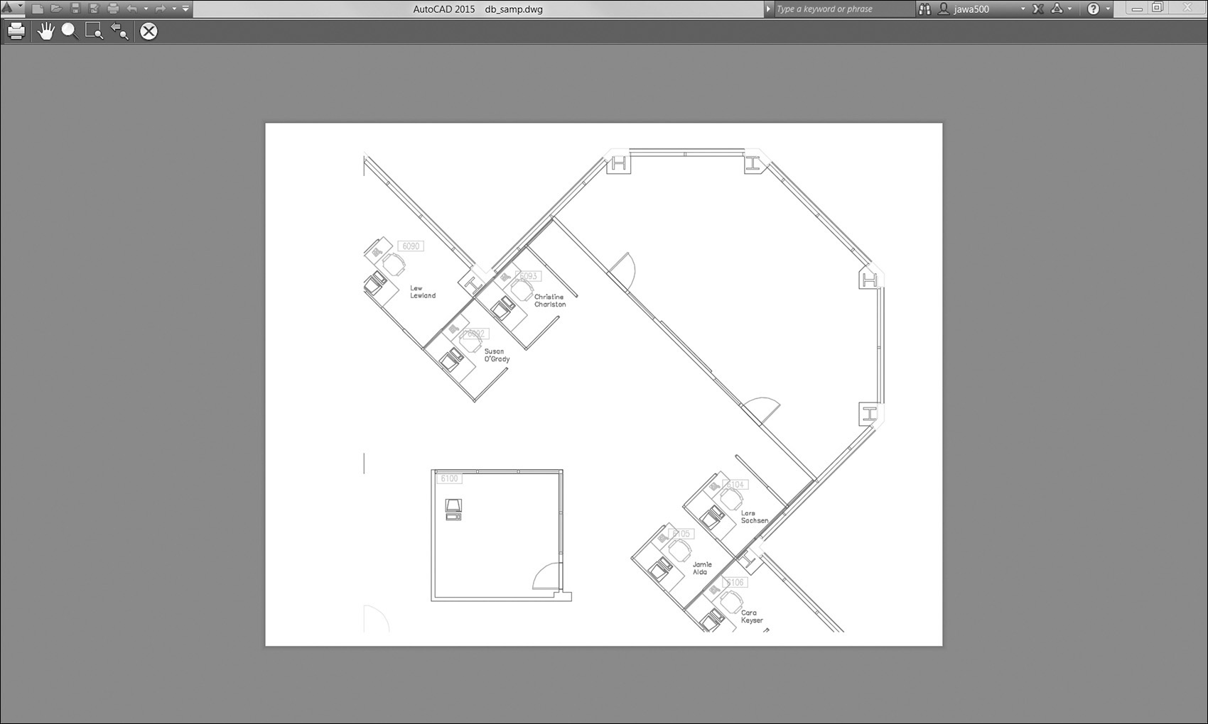
![]() Choose 1/4″ = 1′-0″ from the Scale list. Select the Preview... button. AutoCAD displays the plot preview as shown in Figure 15-6.
Choose 1/4″ = 1′-0″ from the Scale list. Select the Preview... button. AutoCAD displays the plot preview as shown in Figure 15-6.
![]() Choose the Close Preview Window button to exit the plot preview, and choose Cancel to close the Plot dialog box. Do not save the drawing.
Choose the Close Preview Window button to exit the plot preview, and choose Cancel to close the Plot dialog box. Do not save the drawing.
Plotting a Page Layout
Plotting a page layout is in many aspects simpler than plotting from model space. In setting up the page layout, you will typically define many or all of the plotting defaults. However, when you plot, you will still want to double-check your plot settings and do a plot preview before sending it to the printer. This also gives you the opportunity to temporarily override plot settings for any given plot.
Exercise 15-2 Plotting a Page Layout
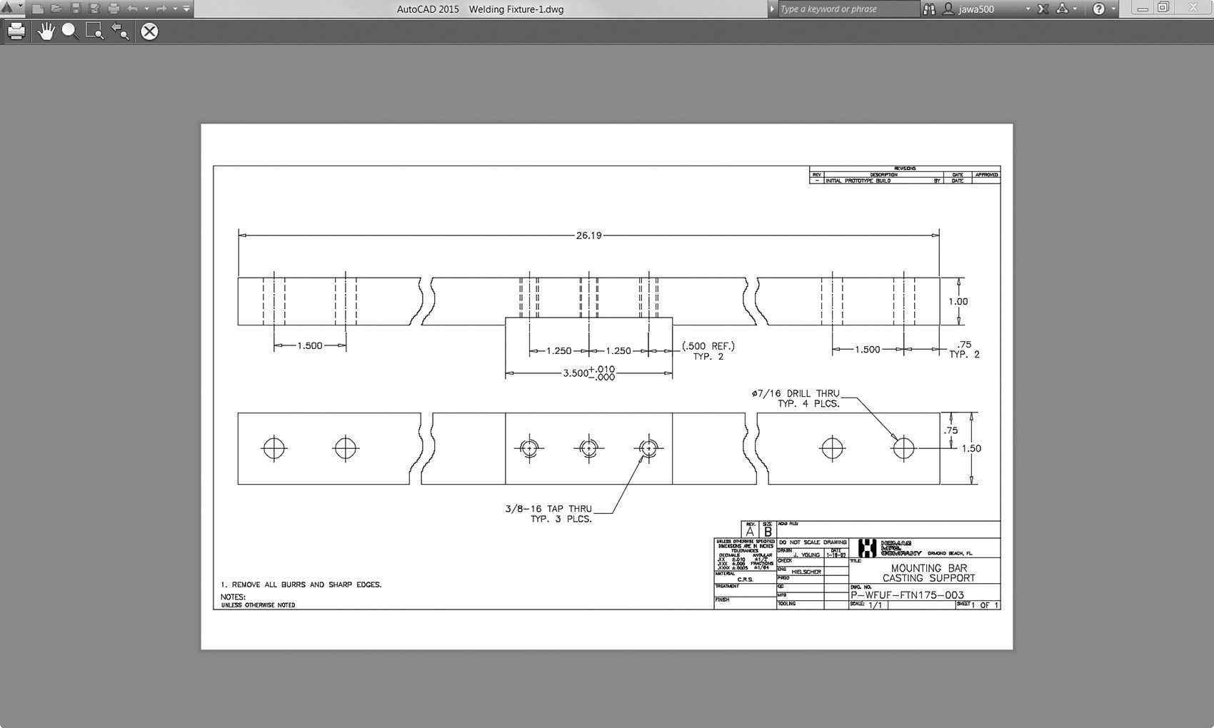
![]() Open drawing Welding Fixture-1 in the student data files.
Open drawing Welding Fixture-1 in the student data files.
To access student data files, go to www.pearsondesigncentral.com.
![]() Select the Mounting Bar Casting Support page layout tab.
Select the Mounting Bar Casting Support page layout tab.
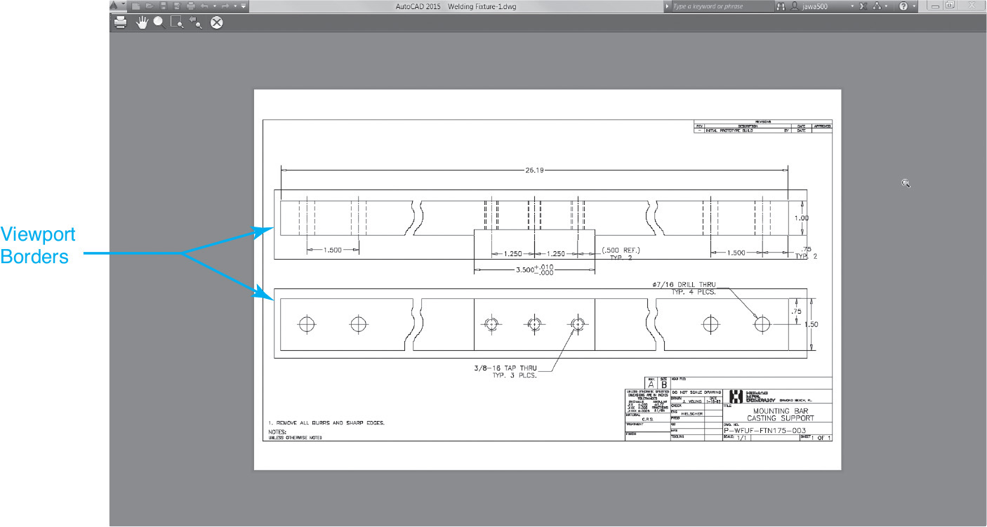
![]() Start the PLOT command to display the Plot dialog box, and select the Preview... button to display the plot preview. Notice that the viewports are displayed on the plot preview (see Figure 15-7). This is because the viewports are currently on a plotting layer.
Start the PLOT command to display the Plot dialog box, and select the Preview... button to display the plot preview. Notice that the viewports are displayed on the plot preview (see Figure 15-7). This is because the viewports are currently on a plotting layer.
![]() Choose the Close Preview Window button to exit the plot preview, and choose Cancel to close the Plot dialog box.
Choose the Close Preview Window button to exit the plot preview, and choose Cancel to close the Plot dialog box.
![]() Select the two viewports, and choose Viewport from the Layer drop-down list. This places the viewports on the nonplotting Viewport layer.
Select the two viewports, and choose Viewport from the Layer drop-down list. This places the viewports on the nonplotting Viewport layer.
![]() Restart the PLOT command. Notice that the plot preview area shows a red bar on the right-hand side of the page. This is because the Plot offset X value is set to 0.010.
Restart the PLOT command. Notice that the plot preview area shows a red bar on the right-hand side of the page. This is because the Plot offset X value is set to 0.010.
![]() Set the X value in the Plot offset to 0.00, and select the Preview... button. This displays the plot preview. The plot preview now looks correct, and the drawing is ready to plot (see Figure 15-8).
Set the X value in the Plot offset to 0.00, and select the Preview... button. This displays the plot preview. The plot preview now looks correct, and the drawing is ready to plot (see Figure 15-8).
![]() Choose the Close Preview Window button to exit the plot preview, and choose Cancel to close the Plot dialog box. Do not save the drawing file.
Choose the Close Preview Window button to exit the plot preview, and choose Cancel to close the Plot dialog box. Do not save the drawing file.
Default Plot Settings and Page Setups
Keep in mind that each drawing environment (model space and each layout) has a set of default plot settings associated with it. A page setup is a collection of default plot settings that are assigned a name and saved in the drawing. Once a page setup is created, its settings can be applied to a given drawing space. Model space page setups can be applied to the model space environment, and layout page setups can be applied to layout (paper) spaces.
Selecting a Page Setup
In the Plot dialog box, the Page setup area allows you to apply the settings stored in a page setup to the current plot. When you start the PLOT command, AutoCAD displays the name of the current page setup in the Name: drop-down list. When you select the Name: drop-down list, you’ll see a list of page setups stored in the drawing. Selecting one of these page setups will apply the settings stored in the page setup to the current plot.
In addition to page setups, there are three additional items in the Name list: <None>, <Previous plot>, and Import.... The <None> setting tells you that the current plot settings do not match any stored page setups. If you are using a page setup and make any changes to the setting in the Plot dialog box, the Name setting will change to <None>, noting that the current plot settings no longer match the settings stored in the page setup.
The <Previous plot> setting will reuse the settings from the last successful PLOT command.
Importing a Page Setup
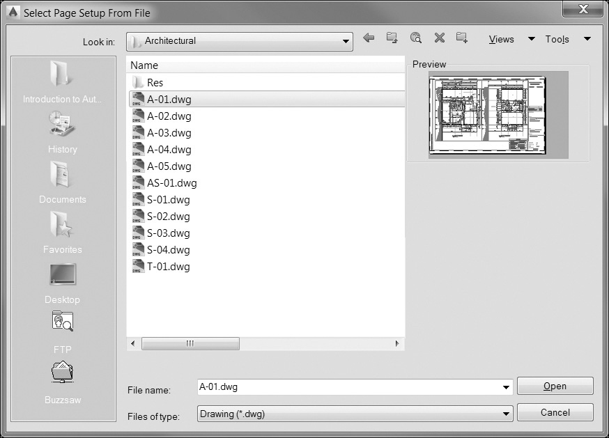
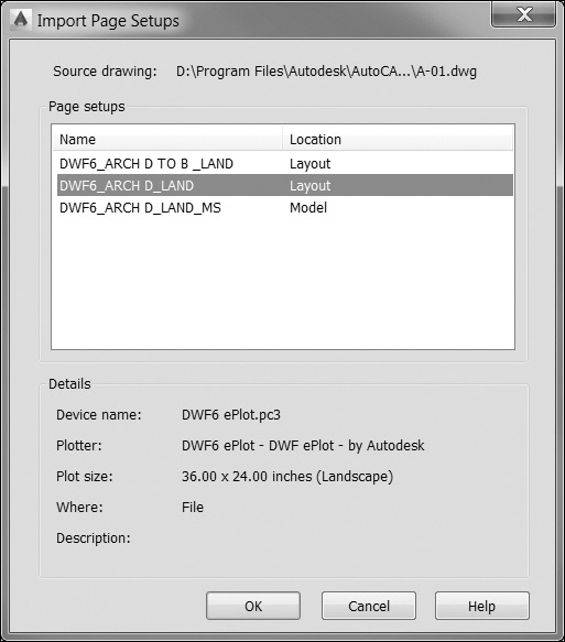
Selecting Import... from the Name list allows you to import a page setup from another drawing. When you select Import..., AutoCAD displays the Select Page Setup From File dialog box (see Figure 15-9), which allows you to select a drawing file. Once you select a drawing file, AutoCAD will display the Import Page Setups dialog box (see Figure 15-10), which displays all the saved page setups within a drawing. Select a page setup from the dialog box, and choose OK to import the page setup into your current drawing. The imported page setup will now be listed in the Name drop-down list so you can select it.
Creating a Page Setup
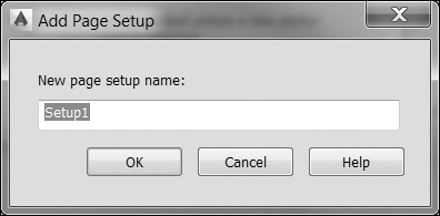
AutoCAD also allows you to save your current plot settings to a page setup. Once you have your plot settings to your liking, choose the Add... button in the Page setup area. AutoCAD will display the Add Page Setup dialog box (see Figure 15-11). Simply type a name and choose OK to save the current plot settings to the new page setup.
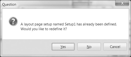
You can update an existing page setup by entering the existing page setup name into the Add Page Setup dialog box. AutoCAD will display a Question dialog box (see Figure 15-12) telling you the page setup already exists and asking whether you’d like to redefine it. Choose Yes to update the existing page setup with the current plot settings.
Applying Plot Settings to the Current Layout
As we mentioned earlier, each drawing space has a set of default plot settings. The Apply to Layout button allows you to take the settings displayed in the Plot dialog box and apply them to the current layout. These settings then become the default plot settings for that layout or model space.
Plot Styles and Lineweights
As noted earlier in the chapter, in the early days of AutoCAD, pen plotters were commonly used. These plotters typically had a pen carousel in which you loaded pens. You would load pens with different pen widths or different colors in each position in the carousel. You would also have a pen table that would tell AutoCAD which pen to use for each AutoCAD color. For example, use pen 4 for color 1, pen 2 for colors 2 and 3, etc. Modern printers no longer use physical pens, but AutoCAD still allows you to use pen tables to control the final look of your plot. Today, AutoCAD refers to these pen tables as plot styles.
A plot style is a table of settings that allows you to control all aspects of your plotted output. For example, you may have a plot table that converts AutoCAD colors to grayscale colors or a plot table that allows you to screen back certain colors.
There are two types of plot styles: named plot styles and color-dependent plot styles. Named plot styles are stored in .STB files. Color-dependent plot styles are stored in .CTB files. A drawing can use either color-dependent plot styles or named plot styles, but not both. By default, color-dependent plot styles are used for new drawings.
named plot style: Plot style that is organized by a user-defined name. Named plot styles are stored in .STB files.
color-dependent plot style: Plot style that is organized by the AutoCAD Color Index (ACI) number. Color-dependent plot styles are stored in .CTB files.
You can change the default plot style type used for new drawings by selecting the Plot Style Table Settings button on the Plot and Publish tab of the Options dialog box.
Plot Style Manager
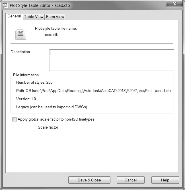
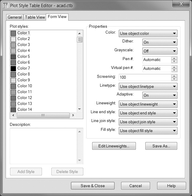
The STYLESMANAGER command will open the folder where the plot style table files are stored (see Figure 15-13). From this folder, double-clicking on a .CTB or an .STB file will start the Plot Style Table Editor application (see Figure 15-14). This is a stand-alone Windows program that runs outside of AutoCAD. This program allows you to create and modify AutoCAD plot style tables. The General tab displays information about the plot style. The Table View and Form View tabs display the table settings in different formats. The Form View tab (see Figure 15-15) is useful for setting the properties of multiple colors at once. In this view, you can select multiple pens and apply settings to them in a single step.

Plot Style Manager |
|
Ribbon & Panel: |
|
Menu: |
File | Plot Style Manager... |
Command Line: |
STYLESMANAGER |
Command Alias: |
None |

Color-Dependent Plot Styles
Color-dependent plot styles map AutoCAD colors within your drawing to specific plotter settings. When you use color-dependent plot styles, all objects with the same color are plotted with the same plotter settings.
Note
The specifics of each of these settings are beyond the scope of this text. For detailed information on these settings, choose the Help button on the Plot Style Table Editor application. Keep in mind that some settings (such as pen numbers and virtual pen numbers) may not be supported by your specific printer. Refer to your printer documentation to see which features are supported.
Named Plot Styles
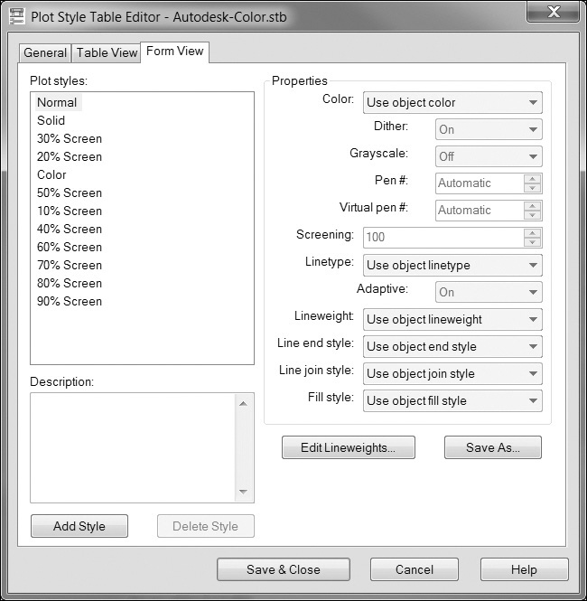
Named plot styles allow you to assign plotter settings directly to AutoCAD objects or AutoCAD layers. Within each .STB file, plotter settings are assigned to plot style names (see Figure 15-16). These plot styles are then assigned to each drawing layer and therefore to each object in the drawing. When named plot styles are used in a drawing, the Plot Style column is enabled in the Layer Properties Manager palette (see Figure 15-17). This allows you to assign a named plot style to a layer.
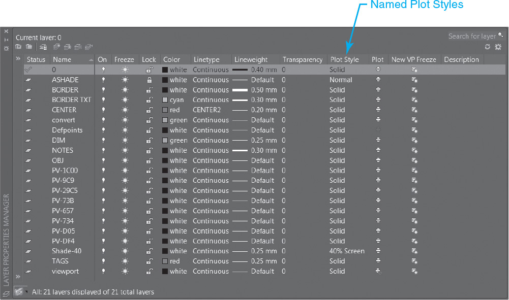
When using named plot styles, the plot style name behaves like other object properties. By default, plot styles are assigned by layer, but you can hard-code a plot style for any specific object.
When using named plot styles, AutoCAD creates a plot style called Normal. This is AutoCAD’s default named plot style name and is included in each .STB file. This is similar to the 0 layer name and the Continuous linetype. It cannot be deleted and is always available.
Using Plot Styles
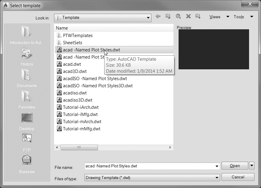
As mentioned earlier, an AutoCAD drawing can use either color-dependent plot styles or named plot styles but not both. When you create a new drawing file, the drawing template typically determines whether AutoCAD uses color-dependent plot styles or named plot styles as well as the default plot style file (see Figure 15-18).
Note
When plotting from model space, selecting a plot style table will cause AutoCAD to ask whether you want this plot style table applied to all paper space layouts. If you answer Yes, AutoCAD will update the default plot settings for each layout to use the selected plot style table.
Once a drawing has been created and the type of plot styles has been set, the Plot style table area of the Plot dialog box will show either .STB or .CTB files. From this list, you can tell AutoCAD which plot style table to use for your plot.
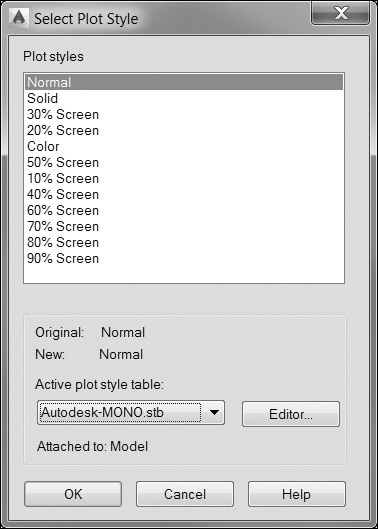
When working with named plot styles, it is possible to assign a plot style table that does not include plot styles that are used in your drawing. For example, say you create a drawing and assign the plot style named 40% Screen that’s defined in the Autodesk-MONO.STB file. If you then select the ACAD.STB plot style table, the 40% Screen style is not defined in that .STB file. When this happens, AutoCAD will display the Select Plot Style dialog box (see Figure 15-19) and ask you to select a different plot style for that layer.
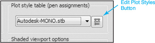
When you select a plot style table, the Edit plot styles button is enabled (see Figure 15-20), which starts the Plot Style Table Editor application (see Figure 15-14). This allows you to view and/or modify the selected plot style table.
Tip
You can use the CONVERTPSTYLES command to convert a named plot style drawing to a color-dependent plot style drawing or vice versa.

Plot Options
The Plot options area of the Plot dialog box allows you to specify options for plotting lineweights, transparency, plot styles, shaded plots, and the order in which objects are plotted.
Plot in Background
This option specifies that the plot is processed in the background. Typically, when you plot, AutoCAD stops all other activity while the drawing is plotting and will show you a plotting progress bar (see Figure 15-21).
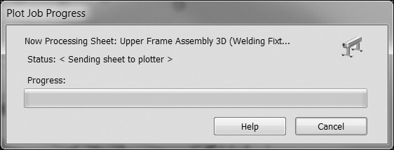
When the Plot in background option is turned on, AutoCAD will return you to the drawing environment and process the plot in the background. This allows you to work while the plot is being generated, but may also increase the time it takes to plot the drawing.
Plot Object Lineweights
This option specifies whether lineweights assigned to objects and layers are plotted. When turned on, any lineweight information assigned in your drawing will be applied to the plot. When turned off, a lineweight of 0 will be applied to all objects in the plot, which results in all objects being plotted with a very thin lineweight.
Plot Transparency
This option specifies whether any objects with transparency levels greater than 0 get plotted with solid or transparent settings.
Plot with Plot Styles
This option specifies whether plot styles applied to objects and layers are plotted. This means that the plot style settings contained in the specified .CTB or .STB file will be applied to the plot. When you select this option, the Plot object lineweights option is automatically enabled.
Plot Paperspace Last
This option allows you to control which space is plotted first. Generally, paper space geometry is usually plotted before model space geometry. Turning this option on will force AutoCAD to plot the model space geometry first.
Hide Paperspace Objects
This option typically affects only 3D drawings and is available only when plotting from a paper space layout. When plotting a 3D object, you may want to have AutoCAD do a hidden line removal, which eliminates any lines appearing behind a 3D object. This option tells AutoCAD whether the hidden line removal process applies to objects in paper space as well as objects in model space.
Plot Stamp On
Turning this option on places a plot stamp on a specified corner of each drawing and/or logs it to a file.
Save Changes to Layout
This option saves the changes that you make to the layout in the Plot dialog box.
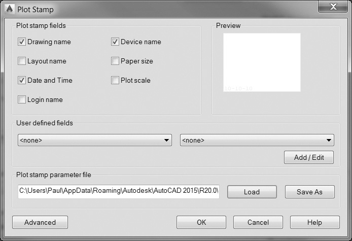
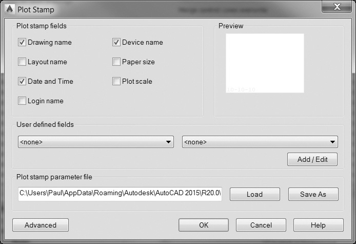
Plot stamp settings are specified in the Plot Stamp dialog box (see Figure 15-22), which allows you to control the information that you want to appear in the plot stamp, such as drawing name, date and time, plot scale, and so on. To open the Plot Stamp dialog box, turn on the Plot stamp on option and then click the Plot Stamp Settings button, which is displayed on the right.
Tip
You can also open the Plot Stamp dialog box by clicking the Plot Stamp Settings button on the Plot and Publish tab of the Options dialog box.
From the Plot Stamp dialog box, you can select what information you want to display, and you can also create user-defined text to display a custom plot stamp.
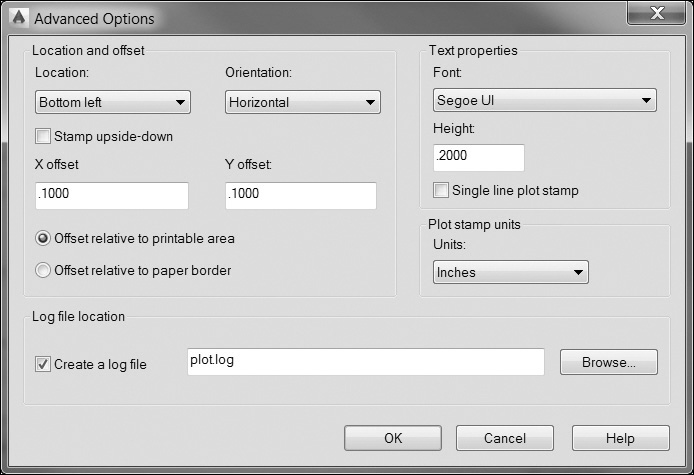
Selecting the Advanced button displays the Advanced Options dialog box (see Figure 15-23), which allows you to control the placement and orientation of the plot stamp as well as the font and height of the plot stamp text.
Plotter Setup
The Printer/plotter area of the Plot dialog box lists all the printers available when plotting a drawing. To select a printer, simply select it from the Name: list. Once selected, AutoCAD will display information about the printer beneath the name, including the name of the printer driver, the printer port, and any description about the printer. The list of printers is divided into two types: Windows-configured printers and AutoCAD-configured printers.
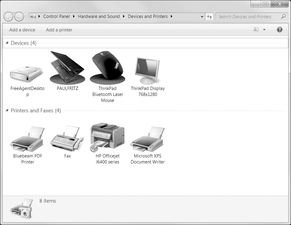
Windows System Printers
The Windows printers are printers that are configured with the Printers applet in the Windows Control Panel (see Figure 15-24). These are printers that are available to all Windows applications.
AutoCAD Printers
AutoCAD printers are configured and controlled by AutoCAD directly. They bypass the Windows printing system and allow AutoCAD to print directly to the printer. AutoCAD-configured printers may also have features available that are not available in a Windows printer. There are also AutoCAD printer drivers that allow you to convert AutoCAD drawings to various raster and vector file formats, such as JPG, BMP, or HPGL.
.PC3 and .PMP Files
AutoCAD-configured printers are stored in plotter configuration files (.PC3 files). These files are also listed in the Printer/plotter Name list (see Figure 15-25).
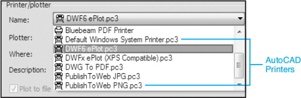
In addition to .PC3 files, AutoCAD also uses plot model parameter (.PMP) files to store custom plotter calibration settings as well as user-defined custom paper sizes.
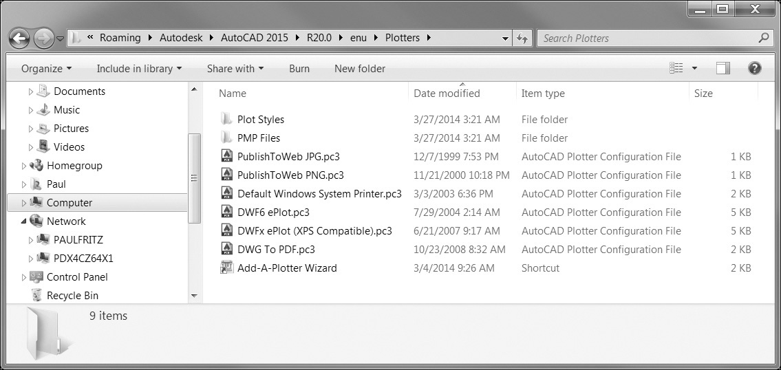
Plotter Manager
The PLOTTERMANAGER command displays the folder containing AutoCAD .PC3 files (see Figure 15-26). From this folder, you can create new plotter configurations and modify existing ones.
Plotter Manager |
|
Ribbon & Panel: |
Output | Plot
|
Menu: |
File | Plotter Manager... |
Command Line: |
PLOTTERMANAGER |
Command Alias: |
None |

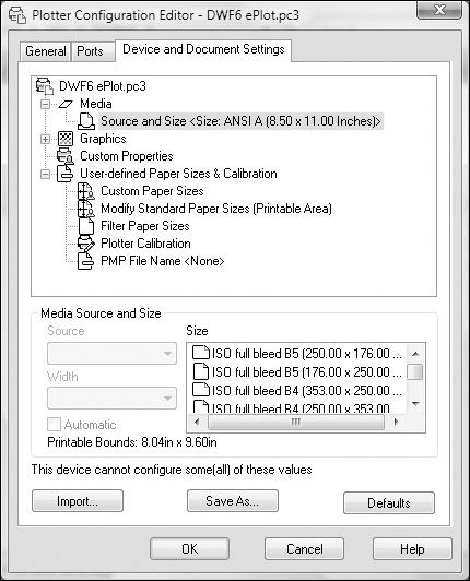
Plotter Configuration Editor
To modify an existing .PC3 file, simply double-click the file. This displays the Plotter Configuration Editor (see Figure 15-27). From this dialog box, you can view and modify settings specific to the printer such as the printer port, custom page sizes, and printable areas.
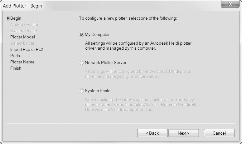
Add-a-Plotter Wizard
The Add-a-Plotter wizard walks you through the process of creating a new plotter configuration file (see Figure 15-28). This wizard allows you to create a new plotter configuration using either AutoCAD-supplied print drivers, or drivers supplied by the printer manufacturer, or by importing a plotter configuration file from an earlier version of AutoCAD (.PCP or .PC2 files).
Overriding a .PC3 File
When you select a printer from the Printer/plotter Name list, the Properties... button is enabled. When you select this button, AutoCAD displays the Plotter Configuration Editor (see Figure 15-27). This allows you to make changes to the plotter configuration within the PLOT command. When you make changes to the plotter configuration from within the PLOT command, AutoCAD will ask you whether you want to save the changes to the .PC3 file or make the changes only for the current plot.
Exercise 15-3 Adding a New Plotter
![]() Open drawing db_samp located in the student data files.
Open drawing db_samp located in the student data files.
To access student data files, go to www.pearsondesigncentral.com.
![]() Start the PLOTTERMANAGER command to display the Plotters folder.
Start the PLOTTERMANAGER command to display the Plotters folder.
![]() Double-click the Add-a-Plotter wizard. AutoCAD displays the Add Plotter dialog box. Choose Next to begin the wizard.
Double-click the Add-a-Plotter wizard. AutoCAD displays the Add Plotter dialog box. Choose Next to begin the wizard.
![]() Choose My Computer to tell AutoCAD that the printer will be controlled locally from your computer (see Figure 15-28). Choose Next to continue to the Plotter Model step.
Choose My Computer to tell AutoCAD that the printer will be controlled locally from your computer (see Figure 15-28). Choose Next to continue to the Plotter Model step.
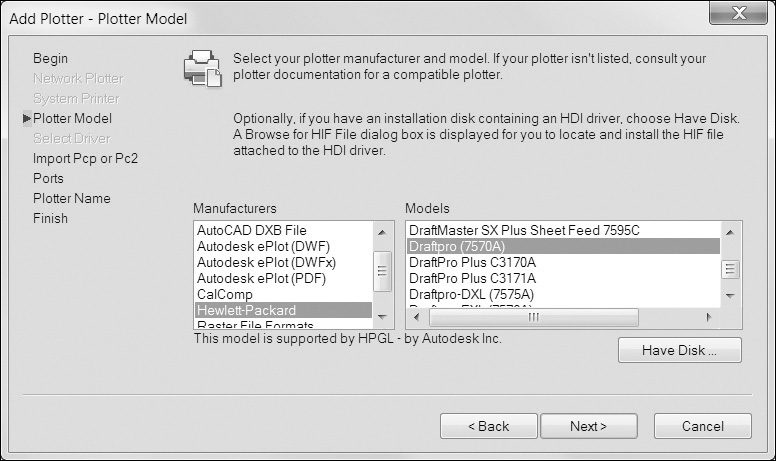
![]() Choose Hewlett-Packard in the Manufacturers list and Draftpro (7570A) in the Models list (see Figure 15-29). Choose Next to continue to the Import Pcp or Pc2 step.
Choose Hewlett-Packard in the Manufacturers list and Draftpro (7570A) in the Models list (see Figure 15-29). Choose Next to continue to the Import Pcp or Pc2 step.
![]() You are given the opportunity to import a .PCP or .PC2 file from an older version of AutoCAD. Choose Next to continue to the Ports step.
You are given the opportunity to import a .PCP or .PC2 file from an older version of AutoCAD. Choose Next to continue to the Ports step.
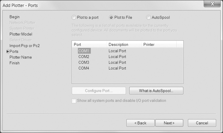
![]() Because this plotter is not actually hooked up to your computer, select the Plot to File option (see Figure 15-30). This will redirect the printer output to a file. Choose Next to continue to the Plotter Name step.
Because this plotter is not actually hooked up to your computer, select the Plot to File option (see Figure 15-30). This will redirect the printer output to a file. Choose Next to continue to the Plotter Name step.
![]() Accept the default name of DraftPro (7570A). Choose Next to continue to the Finish step.
Accept the default name of DraftPro (7570A). Choose Next to continue to the Finish step.
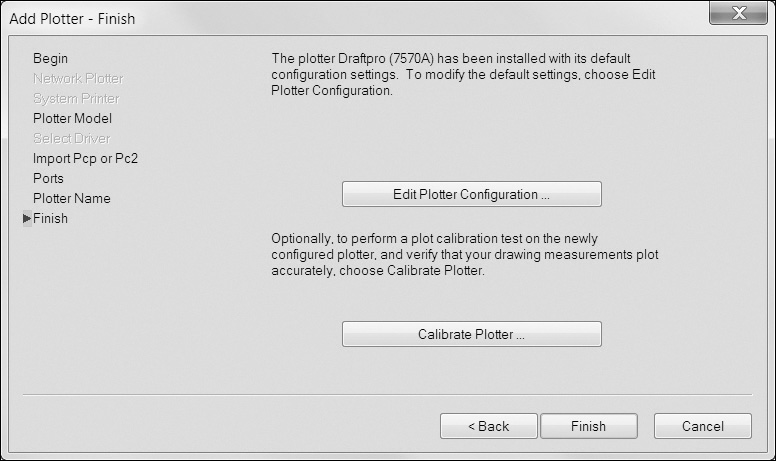
![]() At this point, you can modify the plotter defaults by choosing the Edit Plotter Configuration... button (see Figure 15-31). The Calibrate Plotter... button allows you to verify the accuracy of the plotter output by creating a sample plot, measuring the output, and inputting the measured results back into the plotter calibration. Choose Finish to complete the plotter configuration.
At this point, you can modify the plotter defaults by choosing the Edit Plotter Configuration... button (see Figure 15-31). The Calibrate Plotter... button allows you to verify the accuracy of the plotter output by creating a sample plot, measuring the output, and inputting the measured results back into the plotter calibration. Choose Finish to complete the plotter configuration.
![]() From AutoCAD, start the PLOT command. The Draftpro (7570A).PC3 file is now listed in the Printer/plotter Name list.
From AutoCAD, start the PLOT command. The Draftpro (7570A).PC3 file is now listed in the Printer/plotter Name list.
![]() Choose Cancel to close the Plot dialog box. Do not save the drawing.
Choose Cancel to close the Plot dialog box. Do not save the drawing.
Plotting to a File
As mentioned earlier, when you select a plotter in the Plot dialog box, AutoCAD will display information about the printer, including the port. The port describes where the plot output will be directed—for example, a USB port, an LPT port, or a network printer location. The output port for any particular printer is defined within the plotter configuration (.PC3) file for the printer and is displayed next to the Where: label in the plotter description in the Printer/plotter area of the Plot dialog box.
It is possible to redirect the output to a file by selecting the Plot to file check box directly below the plotter description.
In addition, it is possible to create other file formats via the PLOT command by selecting their corresponding .PC3 file, such as DWF and PDF files. They are all explained in the following sections.
Plot File—PLT
The Plot to file box in the Plot dialog box allows you to redirect the output from the specified port to a plot file. Plot files can be used in various ways. Some office environments use plot management software that may require plot files. Some plot files can be used in other programs. The Hewlett-Packard Graphics Language (HPGL or HPGL/2) is a plot file format used in many Hewlett-Packard plotters. Some graphics programs support HPGL files instead of AutoCAD files. If you have a need to create a plot file, select the Plot to file option in the Plot dialog box. When you plot, AutoCAD will ask you for the name and location of the plot file. Plot files typically use a .PLT file extension.
Design Web Format File—DWF/DWFx
The Design Web Format (DWF) is a file format developed by Autodesk that allows you to publish your drawing on the World Wide Web or an intranet network. DWF files can contain one or more drawing sheets (layouts) and also support real-time panning and zooming as well as control over the display of layers and named views. DWF files cannot be opened in AutoCAD, but they can be attached as underlays.
Note
The DWFx format allows you to view drawings using Microsoft’s XPS Viewer, which is automatically installed with Windows and Internet Explorer version 7 and higher.
DWF files can be reviewed, marked up, and plotted using the free Autodesk® Design Review software. DWF files can also be viewed and shared using Autodesk’s free Web service named Freewheel at http://freewheel.autodesk.com.
To plot to a DWF file, select either the DWF6 ePlot.pc3 or the DWFx ePlot (XPS compatible).pc3 plot configuration in the Printer/plotter Name list. To change the DWF preferences, choose the Properties... button in the Plot dialog box, choose the Custom Properties on the Device and Document Settings tab of the Plotter Configuration Editor dialog box, and then select the Custom Properties... button (see Figure 15-32). The DWF6 ePlot Properties dialog box is shown in Figure 15-33.
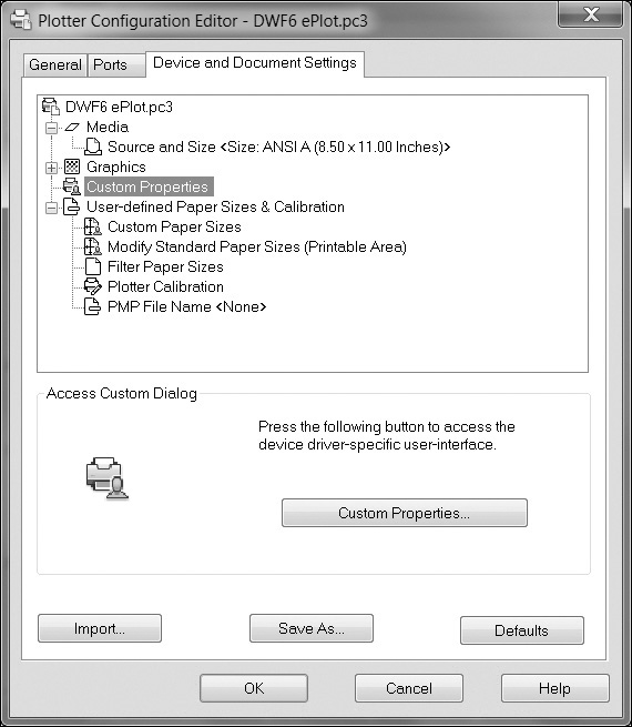
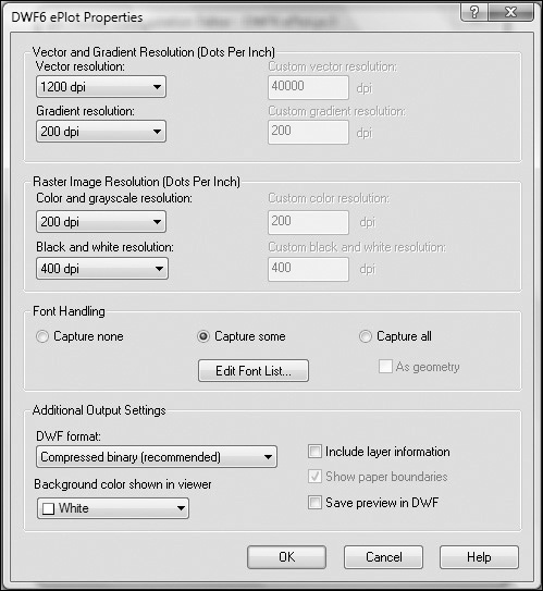
In this dialog box, you can set the resolution of the raster and vector components of the DWF file, control which fonts are embedded in the DWF file, set the background color, and control whether layer control is included in the DWF file.
Adobe® Portable Document Format—PDF.
PDF files are the industry standard for sharing graphical information. Using PDF files, you can share drawings with almost anyone because the Adobe Reader® is already installed on most computers. If the Adobe Reader is not installed, it can be easily downloaded and installed for free from the Internet, most of the time, automatically.
To plot to a PDF file, select the DWG to PDF.PC3 plot configuration in the Printer/plotter Name list. When you plot, the standard Windows file dialog box is displayed so that you can specify a file name and location to save the PDF file.
Tip
It is possible to skip the PLOT command and export one or more layouts directly to a DWF or PDF file via the Export to DWF/PDF panel on the Output tab of the ribbon.
Raster Image File—BMP/CALS/JPEG/PNG/TIFF
AutoCAD comes with a number of plot drivers that allow you to plot to various raster file formats. When you plot a drawing to a raster file, AutoCAD objects are converted to a series of pixels. When plotting to a raster image file, sheet size is measured in pixels instead of inches or millimeters. The resolution and color depth of the raster file determines the quality of the final output and also affects the size of the final file.
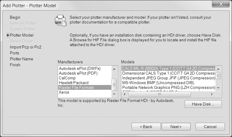
To configure AutoCAD to plot to a raster image file, run the Add-a-Plotter wizard, select My Computer, Next, and choose Raster File Formats in the Manufacturers list (see Figure 15-34). AutoCAD provides support for a number of raster file formats.
Exercise 15-4 Plotting to a File
![]() Continue from Exercise 15-3.
Continue from Exercise 15-3.
![]() Start the PLOT command to display the Plot dialog box.
Start the PLOT command to display the Plot dialog box.
![]() Select the DWF6 ePlot.pc3 printer, and then select the ARCH D (36.00 × 24.00 Inches) paper size.
Select the DWF6 ePlot.pc3 printer, and then select the ARCH D (36.00 × 24.00 Inches) paper size.
![]() Select Extents from the What to plot: list.
Select Extents from the What to plot: list.
![]() Remove the check from the Fit to paper box and choose 3/32″ = 1′-0″ from the Scale list.
Remove the check from the Fit to paper box and choose 3/32″ = 1′-0″ from the Scale list.
![]() Choose the Center the plot option in the Plot offset area, and select the Preview... button.
Choose the Center the plot option in the Plot offset area, and select the Preview... button.
![]() AutoCAD will display the plot preview. You can zoom and pan to examine the plot preview. When done, choose the Plot button to create the plot.
AutoCAD will display the plot preview. You can zoom and pan to examine the plot preview. When done, choose the Plot button to create the plot.
![]() AutoCAD prompts you for the name and location of the plot file. Save the plot as CH15_EXERCISE4.DWF, and choose Save to create the DWF file. AutoCAD plots the drawing and ends the PLOT command.
AutoCAD prompts you for the name and location of the plot file. Save the plot as CH15_EXERCISE4.DWF, and choose Save to create the DWF file. AutoCAD plots the drawing and ends the PLOT command.
Plotting a Set of Drawings
Although the PLOT command allows you to create a single plot, there are many times when you need to create a set of drawings. This might include multiple layouts within a single drawing or include layouts from other drawing files. You may even need to mix model space plots with paper space layout plots. AutoCAD’s PUBLISH command allows you to create multiple plots and to save the settings so the plot set can be re-created.
Batch Plotting
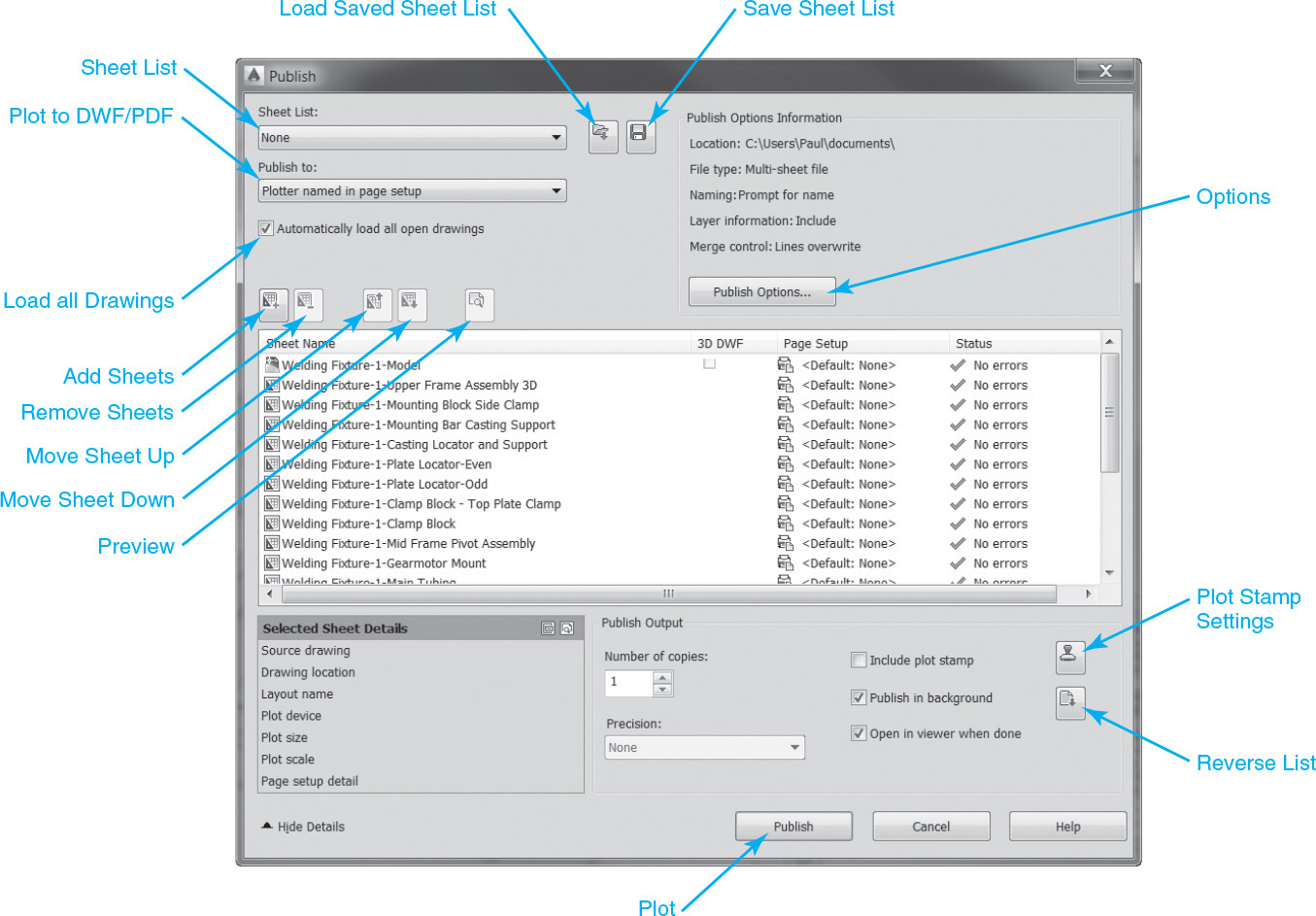
When you start the PUBLISH command, AutoCAD displays the Publish dialog box (see Figure 15-35).
Batch Plot |
|
Ribbon & Panel: |
Output | Plot
|
Menu: |
File | Plot... |
Command Line: |
PUBLISH |
Command Alias: |
None |

When the PUBLISH command starts, AutoCAD automatically imports all the currently open drawings and shows them in the list. The drawings are listed by their file name and drawing tab name and also show the current page setup and the status of the last plot. You can change the page setup used for a plot sheet by selecting the page setup and selecting an available page setup from the drop-down list. You can also import page setups from other drawings to use in your plot sheet set.
Note
You can set the PUBLISH command not to automatically load all open drawings by unchecking Automatically load all open drawings at the upper left of the dialog box.
Tip
It is possible to save a list of sheets to a .dsd (Drawing set Description) file so that you can plot the same list of sheets again in the future by selecting the Save Sheet List button. Select the Load Saved Sheet List button to load a previously saved list. The Sheet List: drop-down list allows you to quickly select previous sheet lists.
Creating a Plot File Drawing Set
The Add and Remove buttons allow you to make changes to the list of plot sheets. To remove a plot sheet from the list, simply select the plot sheet(s) and choose the Remove button.
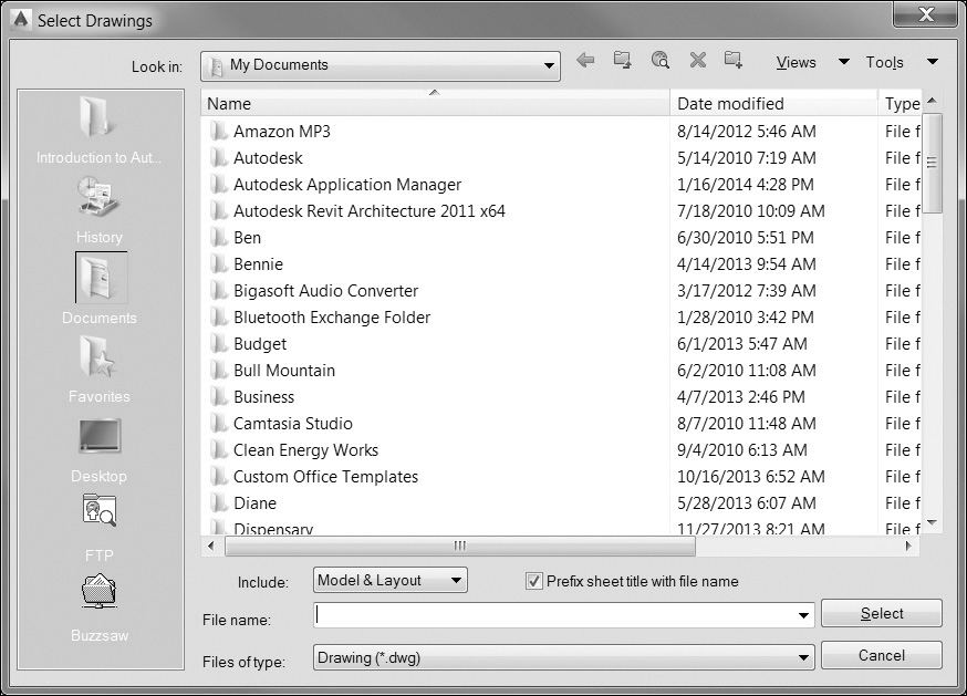
To add plot sheets to the list, choose the Add button. AutoCAD displays the Select Drawings dialog box (see Figure 15-36), which allows you to select a drawing file. Once you select a drawing, AutoCAD will add a plot sheet for each drawing tab in the selected drawing. You can control whether AutoCAD imports model space and/or layout tabs using the Include: drop-down list.
The Move Sheet Up and Move Sheet Down buttons allow you to control the order of the plot sheets in the list. AutoCAD will plot the sheets in the order listed in the plot sheet list.
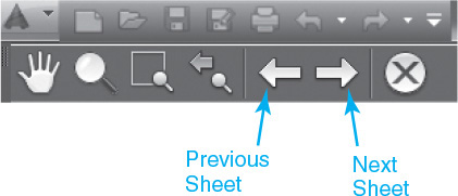
When you’re ready to publish your plot sheet list, the Preview button allows you to see a plot preview of each plot sheet. The PUBLISH command preview mode works exactly like the single sheet plot preview but includes forward and back arrows (see Figure 15-37) that allow you to move through the plot sheet previews.
Creating an Electronic Drawing Set
When you publish a set of plot sheets, you have the option of plotting to the printer defined in the layout or overriding that printer and creating an electronic drawing set in either a DWF, DWFx, or PDF format via the Publish to: drop-down list at the top of the Publish dialog box. When you select either option, AutoCAD will ignore the printer specified in the page setup and create the selected file type. DWF/DWFx files can be viewed and marked up using Autodesk Design Review introduced later in this chapter. PDF files can be viewed using the ubiquitous Adobe Reader, version 7 or later.
The Publish Options... button displays the Publish Options dialog box shown in Figure 15-38 and enables you to view and modify settings for the DWF/PDF output.
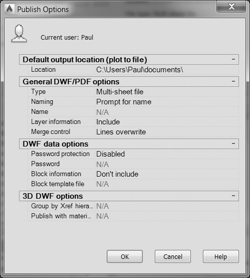
Because DWF/PDF files support multiple sheets, you have the options of printing each sheet to a separate file or plotting all sheets to a single multisheet file. You also have the options of including layer and block information and enabling password protection.
Publish Output
The Include plot stamp option allows you to turn plot stamping on and off. Selecting the Plot Stamp Settings button displays the Plot Stamp dialog box (see Figure 15-39), which allows you to change the plot stamp options.
The Publish in background option allows you to process the list of drawings and layouts in the background so that you can continue to work in AutoCAD. A notification balloon is displayed in the AutoCAD status tray on the right side of the status bar when plotting is complete.
The Open in viewer when done option allows you to view DWF, DWFx, or PDF files in their respective viewer programs when plotting is complete.
Exercise 15-5 Publishing an Electronic Drawing Set
![]() Open drawing Welding Fixture-1 in the student data files. This drawing contains multiple paper space layouts for a welding fixture.
Open drawing Welding Fixture-1 in the student data files. This drawing contains multiple paper space layouts for a welding fixture.
To access student data files, go to www.pearsondesigncentral.com.
![]() Start the PUBLISH command to display the Publish dialog box (see Figure 15-35).
Start the PUBLISH command to display the Publish dialog box (see Figure 15-35).
![]() Because we’re interested in plotting only the paper space layouts, select the Welding Fixture-1-Model sheet from the list of sheet names. Choose the Remove button to remove this sheet from the list.
Because we’re interested in plotting only the paper space layouts, select the Welding Fixture-1-Model sheet from the list of sheet names. Choose the Remove button to remove this sheet from the list.
![]() Select the DWF option from the Publish to: drop-down list to direct the results to a DWF file.
Select the DWF option from the Publish to: drop-down list to direct the results to a DWF file.
![]() Choose the Publish Options... button to display the Publish Options dialog box (see Figure 15-38).
Choose the Publish Options... button to display the Publish Options dialog box (see Figure 15-38).
![]() Verify that the DWF type is set to Multi-sheet file. Choose Include in the Layer information list, and choose OK to close the dialog box.
Verify that the DWF type is set to Multi-sheet file. Choose Include in the Layer information list, and choose OK to close the dialog box.
![]() Choose the Preview button to switch to preview mode. Examine the plot sheets to make sure they look correct. Choose the Close Preview Window button to end the preview.
Choose the Preview button to switch to preview mode. Examine the plot sheets to make sure they look correct. Choose the Close Preview Window button to end the preview.
![]() Choose Publish to create the DWF file. AutoCAD will prompt you for the name of the DWF file. Specify CH15_EXERCISE5.DWF and choose Select to create the DWF file.
Choose Publish to create the DWF file. AutoCAD will prompt you for the name of the DWF file. Specify CH15_EXERCISE5.DWF and choose Select to create the DWF file.
![]() AutoCAD will publish the DWF file and ask you whether you’d like to save the plot sheet list. Choose No to return to the drawing. Do not save the drawing file.
AutoCAD will publish the DWF file and ask you whether you’d like to save the plot sheet list. Choose No to return to the drawing. Do not save the drawing file.
Working with DWF Files
Once you’ve created a DWF file, you have a couple of options for viewing and sharing them. Autodesk Design Review is installed when AutoCAD is installed and is also available as a free download from the Autodesk website for those who do not have AutoCAD.
It is possible to view and share DWF files without Autodesk Design Review software by uploading your file to the Autodesk Freewheel website located at http://freewheel.autodesk.com.
Autodesk Design Review
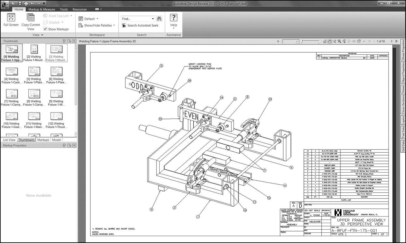
Autodesk Design Review allows you to view, measure, mark up, and print AutoCAD DWF files, making it possible to share your drawings with others who may not have AutoCAD while also maintaining your intellectual property because DWF files cannot be edited. The best part is that Autodesk Design Review is free and easily available at www.autodesk.com. The multisheet DWF file of the Welding Fixture-1 drawing from the last exercise is shown open in Autodesk Design Review in Figure 15-40.
Note
For additional information about the Autodesk Design Review program, please refer to the Autodesk Design Review online help information or go to www.autodesk.com.
Most of the Autodesk Design Review tools are provided on the ribbon at the top of the screen, which has four tabs:
• Home Controls views, workspaces, searching for text, getting help
• Markup & Measure Clipboard, formatting, add callouts, draw tools, measure tools, stamps, and symbols
• Tools Compare sheets, 3D tools, create new sheets by taking snapshot
• Resources Access online resources such as discussion groups, video tutorials, blogs, and additional tools
Navigation tools are located on the toolbar at the upper right of the drawing window so you can pan, zoom, and navigate to the previous or next sheet using the Previous Page or Next Page arrow buttons. The palette at the top left displays all of the open sheet information and has four tabs:
• List View List of sheets
• Thumbnails Previews of sheets
• Markups List of marked-up sheets
• Model Model view
Note
Autodesk Design Review comes with AutoCAD so that you can install it from the AutoCAD installation CD. It is typically installed by default.
Properties for the selected tab are displayed on the palette below. The tabs along the right side of the window display the following information about the drawing in a palette format that is set to Auto-hide by default:
• Sheet Properties Lists the properties for the selected sheet
• Object Properties Lists the properties for the selected object
• Views Lists standard 2D and 3D views created in Autodesk Design Review and views created by AutoCAD
• Cross Sections Lists the cross sections created by you or the publisher of the 3D model
• Layers Lists all layers on the currently displayed sheet
• Text Data Lists all textual data
• Grid Data Lists all detail associated with a selection
Exercise 15-6 Viewing a DWF File
![]() Continue from Exercise 15-5.
Continue from Exercise 15-5.
![]() Start Autodesk Design Review.
Start Autodesk Design Review.
![]() Open the file CH15_EXERCISE5.DWF you created in the previous exercise.
Open the file CH15_EXERCISE5.DWF you created in the previous exercise.
![]() Navigate around the DWF file and examine the multiple plot sheets.
Navigate around the DWF file and examine the multiple plot sheets.
![]() Switch to the Markup & Measure tab and try the different tools.
Switch to the Markup & Measure tab and try the different tools.
Autodesk DWF Writer
The Autodesk DWF Writer is a Windows system printer driver that allows you to publish DWF files by simply selecting Autodesk DWF Writer from your standard Printer Name drop-down list in any Windows application. The DWF Writer allows you to create DWF files from any application that does not offer built-in DWF publishing. The DWF Writer is available as a free download from the Autodesk website (www.autodesk.com).
Chapter Summary
Whether you do quick and dirty check plots to verify your work, create drawing sets to send to contractors, produce full-color presentation drawings, or create electronic plots to share and collaborate with others over the Internet, plotting is an integral part of using AutoCAD. AutoCAD provides a large number of options to precisely control the look and format of your output.
We looked at how page setups are used to manage different plot settings when a drawing is plotted and how they are stored in the drawing. The ability to import page setups means you can set up standard page setups in one or more drawings or template files and then import them on an as-needed basis when you must get a drawing ready to plot.
The use of plot styles to control the output appearance of drawings was introduced. We saw that there are two different approaches to applying plot styles: color dependent and named. The most prevalent is the color-dependent plot styles (.CTB) that allow you to control object output appearance according to its color in a drawing. Named plot styles (.STB) afford you more control because you can assign a different plot style to anything in a drawing regardless of its color, but they also take a lot more work to manage.
An overview of the Plotter Manager to create and manage AutoCAD’s plotter configuration (.PC3) files was provided so that you can add different physical printing devices or the ability to output to different raster file formats.
The ability to output directly to industry standard plot files using the Design Web Format (DWF) and Portable Document Format (PDF) format was explored so that you can share your AutoCAD designs directly with other clients and consultants without the need to print any hard-copy output. Using AutoCAD’s Batch Plotting utility it is even possible to create a complete electronic drawing set in one step.
The best part is, using Autodesk’s free downloadable Design Review software (available at www.autodesk.com), clients and consultants do not even have to have AutoCAD to view, print, and even mark up their drawings.
Chapter Test Questions
Multiple Choice
Circle the correct answer.
1. A page setup is:
a. A paper space layout
b. A set of default plot settings
c. A way to assign lineweights to AutoCAD objects
d. A print driver
2. Which of the following model space plot scales will result in a drawing scaled to 1/2″ = 1′-0″?
a. 5 = 1
b. 1 = 24
c. 24 = 1
d. 1 = .5
3. Named plot style tables are stored in:
a. .CTB files
b. .PC3 files
c. .DWF files
d. .STB files
4. Plotter configurations are stored in:
a. .CTB files
b. .PC3 files
c. .DWF files
d. .STB files
5. To plot everything visible in the drawing, you would set the plot area to:
a. Limits
b. Extents
c. Layout
d. Display
6. A DWF file:
a. Is a Design Web Format file
b. Can be viewed only electronically; it cannot be printed
c. Can be opened in AutoCAD
d. Does not show layer information
7. Which of the following AutoCAD commands does not print drawings?
a. PREVIEW
b. PLOT
c. SAVEAS
d. PUBLISH
8. Color-dependent plot style tables are stored in:
a. .CTB files
b. .PC3 files
c. .DWF files
d. .STB files
9. Plot stamps:
a. Can contain only specific preset information
b. Always appear in the lower left corner of the plot
c. Use only the TXT.SHX text font
d. None of the above
10. Raster files:
a. Contain only pixels, no actual AutoCAD objects
b. Are not supported in AutoCAD
c. Must not exceed 640 × 480 resolution
d. None of the above
Matching
Write the number of the correct answer on the line.
1. True or False: Page setups are used only in layout space.
2. True or False: You can use both color-dependent plot styles and named plot styles within a single drawing.
3. True or False: Page setups can be created with the PLOT command.
4. True or False: DWF files cannot be opened in AutoCAD.
5. True or False: DWF files can contain only a single plot sheet.
6. True or False: DWF files do not support AutoCAD layers.
7. True or False: .PC3 files cannot be modified.
8. True or False: Objects in paper space are always plotted first.
9. True or False: You can publish layouts from multiple drawing files.
10. True or False: Color-dependent plot styles are assigned by layer name.
Chapter Projects
![]() Project 15-1: Classroom Plan, continued from Chapter 14 [BASIC]
Project 15-1: Classroom Plan, continued from Chapter 14 [BASIC]
1. Open drawing P14-1 from Chapter 14.
2. Start the PLOT command so that the Plot dialog box is displayed.
3. Set the Printer/plotter Name to a large-format plotter capable of printing on 36″ × 24″ paper (D-size). If you do not have access to a large-format plotter, set the Printer/plotter Name to DWF6 ePlot.pc3 to create a Design Web Format (DWF) file.
4. Make sure the paper size is correct.
5. Make sure that the Plot area is set to Extents.
6. Select the Center the plot check box in the Plot offset area.
7. Make sure that the Plot scale is set to 1:1.
8. Select the More Options arrow button at the bottom right of the dialog box to display the additional plotting options.
9. Select the monochrome.ctb plot style table.
10. Select the Preview button at the bottom left of the dialog box to preview the plot and make sure that everything is OK.
11. Select the Apply to Layout button at the bottom of the dialog box to save the changes with the layout.
12. Select OK to plot the drawing.
13. Save the drawing as P15-1.
![]() Project 15-2: B-Size Mechanical Border, continued from Chapter 14 [INTERMEDIATE]
Project 15-2: B-Size Mechanical Border, continued from Chapter 14 [INTERMEDIATE]
1. Open template file Mechanical B-Size.DWT from Chapter 14.
2. Start the PLOT command so that the Plot dialog box is displayed.
3. Set the Printer/plotter Name to a printer or plotter capable of printing on 11″ × 17″ paper (B-size). If you do not have access to a printer/plotter that can print 11″ × 17″, set the Printer/plotter Name to DWF6 ePlot.pc3 to create a Design Web Format (DWF) file.
4. Make sure the paper size is correct.
5. Make sure that the Plot area is set to Layout.
6. Make sure that the Plot scale is set to 1:1.
7. Select the More Options arrow button at the bottom right of the dialog box to display the additional plotting options.
8. Select the monochrome.ctb plot style table.
9. Select the Preview button at the bottom left of the dialog box to preview the plot and make sure that everything is OK.
10. Select the Apply to Layout button at the bottom of the dialog box to save the changes with the layout.
11. Select OK to plot the drawing.
12. Save the drawing as a template file named Mechanical B-Size.DWT.
![]() Project 15-3: Architectural D-Size Border, continued from Chapter 14 [ADVANCED]
Project 15-3: Architectural D-Size Border, continued from Chapter 14 [ADVANCED]
1. Open template file Architectural D-Size.DWT from Chapter 14.
2. Start the PLOT command so that the Plot dialog box is displayed.
3. Set the Printer/plotter Name to a large-format plotter capable of printing on 36″ × 24″ paper (D-size). If you do not have access to a large-format plotter, set the Printer/plotter Name to DWF6 ePlot.pc3 to create a Design Web Format (DWF) file.
4. Make sure the paper size is correct.
5. Make sure that the Plot area is set to Layout.
6. Make sure that the Plot scale is set to 1:1.
7. Select the More Options arrow button at the bottom right of the dialog box to display the additional plotting options.
8. Select the monochrome.ctb plot style table.
9. Select the Preview button at the bottom left of the dialog box to preview the plot and make sure that everything is OK.
10. Select the Apply to Layout button at the bottom of the dialog box to save the changes with the layout.
11. Select OK to plot the drawing.
12. Save the drawing to a template file as Architectural D-Size.DWT.
![]() Project 15-4: Optical Mount—English Units, continued from Chapter 14 [INTERMEDIATE]
Project 15-4: Optical Mount—English Units, continued from Chapter 14 [INTERMEDIATE]
1. Open drawing P14-4 from Chapter 14.
2. Start the PLOT command so that the Plot dialog box is displayed.
3. Set the Printer/plotter Name to a large-format plotter capable of printing on 36″ × 24″ paper (D-size). If you do not have access to a large-format plotter, set the Printer/plotter Name to DWF6 ePlot.pc3 to create a Design Web Format (DWF) file.
4. Make sure the paper size is correct.
5. Make sure that the Plot area is set to Layout.
6. Make sure that the Plot scale is set to 1:1.
7. Select the More Options arrow button at the bottom right of the dialog box to display the additional plotting options.
8. Select the monochrome.ctb plot style table.
9. Select the Preview button at the bottom left of the dialog box to preview the plot and make sure that everything is OK.
10. Select the Apply to Layout button at the bottom of the dialog box to save the changes with the layout.
11. Select OK to plot the drawing.
12. Save the drawing as P15-4.
![]() Project 15-5: Residential Architectural Plan, continued from Chapter 14 [ADVANCED]
Project 15-5: Residential Architectural Plan, continued from Chapter 14 [ADVANCED]
1. Open drawing P14-5 from Chapter 14.
2. Start the PLOT command so that the Plot dialog box is displayed.
3. Set the Printer/plotter Name to a large-format plotter capable of printing on 36″ × 24″ paper (D-size). If you do not have access to a large-format plotter, set the Printer/plotter Name to DWF6 ePlot.pc3 to create a Design Web Format (DWF) file.
4. Make sure the paper size is correct.
5. Make sure that the Plot area is set to Layout.
6. Make sure that the Plot scale is set to 1:1.
7. Select the More Options arrow button at the bottom right of the dialog box to display the additional plotting options.
8. Select the monochrome.ctb plot style table.
9. Select the Preview button at the bottom left of the dialog box to preview the plot and make sure that everything is OK.
10. Select the Apply to Layout button at the bottom of the dialog box to save the changes with the layout.
11. Select OK to plot the drawing.
12. Save the drawing as P15-5.