This chapter will introduce you to the world of single-board computers (SBCs). Many of you, hearing this term for the first time, may wonder what an SBC is and what it is used for. This chapter will explain SBCs and how they have developed historically. You will also learn about the most popular SBCs on the market such as Banana Pi, Raspberry Pi, and Arduino. In an in-depth comparison, I will explain the features of popular SBCs with regards to USB, storage, networking, and communication.
You will then learn about the Raspberry Pi and more specifically the Raspberry Pi 3 Model B+ because you are going to use it as a master node in the IoT and IIoT projects in this book. You will also find an in-depth explanation of the GPIO (general purpose input/output) pins located on the Raspberry Pi and their uses. You will then learn about single board micron rollers (SBMs), which are different from single-board computers. The single-board microcontrollers in IoT and IIoT applications are generally used as slaves to the single-board computers like Raspberry Pi. The most popular single-board microcontroller is the Arduino, and you will look at the types of SBMs in a detailed tabular format covering their processors, I/O modules, frequency, voltage, etc.
You will then look at Arduino Mega 2560 and its layout and learn about its GPIO pins. Next, you will learn about the most important topic of the book: IoT sensors and their types and applications. You will use some of them in the case study solutions. Also covered is the topic of drones because they can be used to collect data for a telecom application. Please note that flying drones requires a license in most countries and you should comply before trying to use one for any project. You will also learn about an Modbus device and how it is used to build a commercial application. Lastly, you will learn about the software programs that run all of these devices.
Python version 3.x is used throughout the book. If you have an older version of Python, the code examples may not work. You need Python 3.x or later to be able to run them successfully.
Hardware Requirements
Raspberry Pi 3 Model B+
Arduino Mega 2560
LCD/LED screen to output Raspberry Pi 3 Model B+
Single phase energy meter: Modbus 220/230V, bidirectional, multi-function, RS485, pulse/Modbus output
- Drone: Industrial grade, heavy lifting which meets these specifications:
Max payload: 1.5 kg (3.5 pounds)
Range: 5 km
Time to fly: At least 30 mins
Single-Board Computer
A single-board computer is a completely functional computer set on a single printed circuit board. What makes this type of computer unique is that the entire input, output, and processing such as graphics and numeric calculations all happen on the same board. While a SBC can be built as a high computing server, a more popular version of this type of computer is a small and compact machine.
Historically, SBCs were built to be educational and compact; now they are used in mainstream commercial applications.
Single-board computers are built on different microprocessors but they are all of a simple design. They are built to be handy and compact. Running a fast computer that occupies very little space and is stable and also portable adds to the charm of owning these machines.
One of the early implementations (May, 1976) of single-board computer was called the Diana micro; it was based on the Intel C8080A processor and was a very popular home computer as part of the BigBook series of computers. With the expansion of the PC market, the SBC did not progress further until now, when the PC has almost been replaced by tablets, laptops, and mobiles. You can go to https://en.wikipedia.org/wiki/Single-board_computer for more information.
SBC Features and Advantages
Features | Advantage |
|---|---|
Price | SBCs are available for under $30 each today. |
Form factor | SBCs are very small, almost the size of a palmtop, which makes them portable and handy to use. |
Operating system | Linux variants are most popular. Windows IoT |
Architecture | Two variants: slot support and no slot support. |
Power efficiency | High |
The main reason for the popularity of single-board computers is the price because they are available for under $30 each. Another perk is their compact and handy form factor; they fit the palm of the hand. There are variants that run Linux or Windows IoT or other operating systems. Most of the SBCs do not come with slot support; however, some do to support putting industrial grade cards on them. These small machines are highly efficient in terms of power and can run on home power single phase connections efficiently. Unless you want to plug them into a big LED or LCD screen, they do not need a separate power supply for the screen. They have their own 5-inch or 7-inch LED/LCD flat screens, which can be powered off the SBC itself. There is a flexibility of covers where the single boards can be put inside. From transparent ones to stylish cases to housing for clusters of 4 or 7 SBCs, there is a wide range of options to choose from for today’s SBCs. This availability has extended the appeal of these computers by giving the user the DIY sense of achievement. From choosing the case to installing the operating system to using other types of software, everything is flexible and there are many options to choose from. Now let’s look at the most popular SBCs on the market and their development.
Popular Single-Board Computers on the Market
Popular Single-Board Computers
Name | PCIe | USB[2] | Storage | Networking | Communication | Generic I/O | ||||||||
|---|---|---|---|---|---|---|---|---|---|---|---|---|---|---|
2 | 3 | Device | On-board | Flash slots | SATA | Eth. | Wi-Fi | Bt. | I2C | SPI | GPIO | Analog | ||
Raspberry PiZero W | No | No | No | OTG | No | microSD | No | No | b/g/n | 4.1 + BLE | Yes | Yes | 17 | No |
Raspberry PiZero | No | No | No | OTG | No | microSD | No | No | No | No | Yes | Yes | 17 | No |
Raspberry Pi Model B+ | No | 4 | No | No | No | microSD | No | 10/100 | No | No | Yes | Yes | 17 | No |
Raspberry Pi Model B | No | 2 | No | No | No | SD | No | 10/100 | No | No | Yes | Yes | 8 | No |
Raspberry Pi Model A | No | 1 | No | No | No | SD | No | No | No | No | Yes | Yes | 8 | No |
Raspberry Pi 3 Model B | No | 4 | No | No | No | microSD | No | 10/100 | b/g/n | 4.1 | Yes | Yes | 17 | No |
Raspberry Pi 2 Model B | No | 4 | No | No | No | microSD | No | 10/100 | No | No | Yes | Yes | 17 | No |
Intel Galileo Gen 2[46] | 1 mini | 1 | No | Yes | 8 MB Flash + 8 KB EEPROM | SD | No | 10/100 | No | No | Yes | Yes | 20 | 12-bit ADC, 6 PWM |
Banana Pi M3[137] | No | 2 | No | OTG | 8GB eMMC | microSD | USB to SATA 2.0 adapter | GbE | a/b/g/n | 4 | Yes | Yes | 40 | 12-Bit-ADC (CON1 for Touch) |
Banana Pi M2 | No | 2 | No | OTG | No | microSD | No | GbE | a/b/g/n | No | Yes | Yes | 40 | 12-Bit-ADC (CON1 for Touch) |
Banana Pi[11] | No | 2 | No | OTG | No | SD | SATA 2.0 | GbE | No | No | Yes | Yes | 26 | 12-Bit-ADC (CON1 for Touch) |
As of this writing, the most popular SBCs today are the Raspberry Pi and Banana Pi. They are equally popular with hobbyists and serious users. While Raspberry Pi runs OSes like Noobs, Raspbian, and Windows IoT, Banana Pi run Linux and Android 4.x. Raspberry Pi developed from Model Zero to the current one, which is 3 Model B+ and, as you can see from Table 1-2, there have been huge hardware improvements. Raspberry Pi 3 B+ how has an ARM Cortex-A53 1.4GHz CPU, which is an improvement over the Raspberry Pi 3 B, which had an ARM Cortex-A53 1.2GHz CPU. The RAM size has not changed; however, there is an enhancement in Wi-Fi, which now has the capability of up 5GHz transfers. The Ethernet support has been increased from 100Mbps to 300Mbps. The use of Banana Pi is preferred by users who have projects that are closely linked with mobile applications since the operating system is Android which, although built on Linux, has Android as the kernel for its operations. For the projects in this book I have chosen Raspberry Pi. The operating system we are going to use is Raspbian, which is an adaptation of the Debian OS. We are not using Noobs because we want to make commercial-grade applications on the SBC and we are not using Windows IoT since we need an OS that has a desktop and development IDE embedded in it. So the choice of Raspbian is pretty obvious.
Raspberry Pi Technical Specifications
Raspberry Pi Platform | RAM | Processor | USB | Ethernet | Wi-Fi | Bluetooth | HDMI | Other Video | MicroSD |
|---|---|---|---|---|---|---|---|---|---|
Raspberry Pi A+ | 512MB | 700 MHz ARM11 | 1 port | - | - | - | Yes | DSI, Composite | Yes |
Raspberry Pi B+ | 512MB | 700 MHz ARM11 | 4 ports | 10/100Mbps | - | - | Yes | DSI, Composite | Yes |
Raspberry Pi 2 B | 1GB | 900 MHz Quad-Core ARM Cortex-A7 | 4 ports | 10/100Mbps | - | - | Yes | DSI, Composite | Yes |
Raspberry Pi 3 B | 1GB | 1.2 GHz, Quad-Core 64-bit ARM Cortex A53 | 4 ports | 10/100Mbps | 802.11n | 4.1 | Yes | DSI, Composite | Yes |
Raspberry Pi 3 B+ | 1GB | 1.4 GHz 64-bit ARM Cortex A53 | 4 ports | 300/Mbps/PoE | 802.11ac | 4.2 | Yes | DSI, Composite | Yes |
Raspberry Pi Zero | 512MB | 1 GHz single-core ARM11 | 1 micro USB | - | - | - | Mini-HDMI | - | Yes |
Raspberry Pi Zero Wireless | 512MB | 1 GHz single-core ARM11 | 1 micro USB | - | 802.11n | 4.1 | Mini-HDMI | - | Yes |

GPIO pin overlay for Raspberry Pi 3 Model B+
In Figure 1-1, you can see that there are a total 40 GPIO pins. They have a structure and it is important that you understand it in order to use it. The pins are numbered from 1 to 40 in the diagram. Pin 1 and 17 are for supplying power output to your device (3.5 volts). Pins 2 and 4 are used for giving a power output of 5 volts each. Pins numbered 6, 9, 14, 20, 25, 30, 34 and 39 are used for grounding the circuit. The rest of the pins are used for GPIO. You will be using this information later when you create a complete circuit for some IoT-based solutions.
Let’s now discuss microcontrollers and how they are used.
Single-Board Microcontrollers
SBMs are microcontrollers built into a single circuit board; they are used in industrial and commercial applications to interface between industrial and commercial devices such as ones that use serial bus communication. They are used in applications to develop solutions requiring interfacing with industrial machines or network interfaces such as ones requiring Modbus communication protocol.
Arduino is a very popular single-board microcontroller and is used by hobbyists and students to learn hardware implementations and how to control and build hobby machines that interface with common C and C++ programs. However, we are going to use Arduino for an industrial-grade purpose. Let’s compare three models from the Arduino line in order to select the best microcontroller for our purpose.
Arduino Uno, Arduino Mega, and Arduino Mega 2560 are the three models we are going to use for our comparison. All three single-board microcontrollers use a 16MHz frequency processor. The printed circuit board dimensions of the Mega and Mega 2560 are higher than the Arduino Uno, which is smaller than both of them by half in length at 2.7 inches x 2.1 inches to 4 inches x 2.1 inches. The Arduino Mega 2560 has the highest flash memory of 256kb, whereas Arduino Uno has the lowest flash memory of 32kb. Arduino Mega has 128kb. Flash memory is very important as far as SBMs are concerned because whatever programs you write for controlling the hardware through your application has to be written to the flash memory first. If the flash memory is low, you cannot write an industrial-grade application on top of it. Both the Mega models have higher EEPROM and SRAM than the Arduino Uno; also, the Mega models have 54 GPIO pins while the Uno has just 14 pins. Why do we need more pins for our applications? We will be using our applications for communicating with serial Modbus communication interfaces which may need two or three devices connected at the same time. If the number of pins is less, we will be limited in having parallel devices. So we need higher pins for this purpose.
So the best model for us is the Arduino Mega 2560, which has the highest flash memory.
Arduino Mega 2560
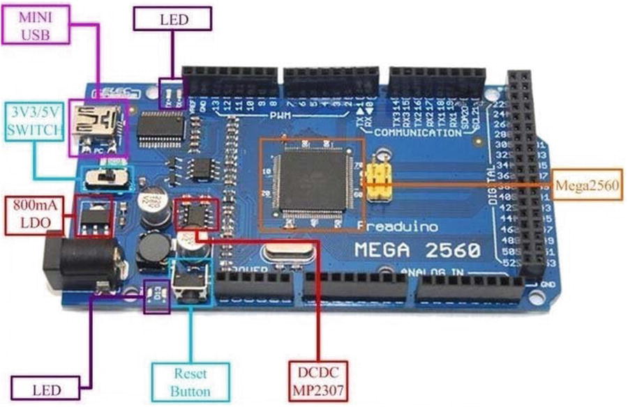
Arduino Mega 2560 architecture

Arduino Mega 2560 GPIO pins overlay
As you can see in the figure, the pin numbers starting from D mean digital pins; these are the slots where you will connect digital sensors and devices. The pins starting from A are analog pins and can be used to communicate with analog devices. For now, this is what you need to understand. You will look at all of this in detail once you start to assemble your system.
IoT sensors
IoT is an extension of internet connectivity to everyday physical devices and objects. When devices like sensors and internet connectivity are added to it and embedded to physical devices like art objects or any other object that display information on creation date, an artist description of the object, recently modified date, etc., then the IoT is formed. We now have the concept of automatic reordering cabinets which can order food online as they gets empty upon consumption. By embedding IoT sensors in everyday objects we are making them smart and accessible for human betterment.
Common Types of IoT Sensors and Their Purposes
Types of Sensors | Purpose |
|---|---|
Machine vision | Optics and ambient light detection |
Proximity and location | GPS location and presence of objects |
Temperature | Detecting atmospheric temperature in air, soil, and water |
Humidity/moisture | Detecting atmospheric humidity in air and soil |
Acoustic | Detecting infra and ultrasound vibrations in the atmosphere |
Chemicals | Detecting gas content in air, soil, and water |
Flow | Detecting air and water flow in enclosed areas such as pipes |
Electromagnetic | Detecting electromagnetic levels in the environment |
Acceleration | Detecting the tilt of a connected electronic device |
Load/weight | Detecting change in load or weight in the environment which is being monitored |
You can see from Table 1-4 that there are a variety of sensors available and they range from digital to analog to measure and detect objects using Wi-Fi cameras to detecting a change in weight or load on an electronic device. The uses and applications of these sensors are limitless and can give fresh life to an IoT application. You will be using these common types of sensors in this book and I will outline them in more detail as you build your solutions.
Drones
A drone is defined by Wikipedia (https://simple.wikipedia.org/wiki/Unmanned_aerial_vehicle) as an unmanned aerial vehicle operated through remote control devices. Drones usually have a small microcontroller embedded inside them which has the capability to detect changes in air pressure, the proximity of objects, acceleration, etc. It has many IoT sensors embedded within it, making it smarter than manned planes. However, there are very few automatic drones that do not require human supervision to fly and work. Most drones have human supervisors who control their activities through a remote control mechanism.
You will be using an industrial grade drone in the solution for the telecom domain case study. You will need an industrial grade drone that can take payloads up to 3.5 pounds or 1.5 kgs and has a range of 5 km since you will be flying it for detection purposes around an area in a particular locality. The minimum flight time you need is 30 minutes because this is the minimum time required to gather some decent data to apply machine learning. These types of drones are definitely not cheap; they start at $2,500.
Modbus Device
You will be using another device in the energy segment of the case study. A Modbus device is a standard communication protocol for connecting to industrial devices, such as machines to a computer. They are also used to gather and send data. There is a master device or microcontroller that uses the Modbus protocol to communicate with its slaves, which can be up to 247 in number. This makes the protocol very robust, which is the reason I chose an Arduino Mega 2560 single-board microcontroller (because it has a lot of space for analog and digital pins on its board for communication).
Before proceeding further, I would like to warn you of the risk associated with using this Modbus device as the energy meter. It is an electric appliance and carries the risk of short-circuiting if not connected properly. It can also be dangerous to human life if not used as per its instruction manual. It can also burn and damage your Raspberry Pi and Arduino boards if wrong connections are made. So if you are not comfortable with electric connections, I strongly advise you to not use this device or to get expert help from a local electrical technician to make the proper connections. Neither I nor the publisher can be held responsible in any way whatsoever for any kind of damages, either material or to life. User discretion is advised.
In the industrial world, three-phase Modbus energy meters are used, but this is difficult to replicate in a normal environment, so I recommend using a single-phase energy meter instead, which uses the Modbus RTU communication protocol. There are plenty of options available from companies such as Schneider Electric and others.
Required Software
For running the exercise in this book, you will need Python 3.x installed. I recommend you use the default Python installation that comes with the Raspbian OS for this purpose. Python is a simple distribution and it does not require any installation whatsoever, unlike Anaconda. All the coding exercises in this book work on this version of Python. The exercises and solutions in this book do not support Windows nor have they been tested on any version of Windows. Using the Raspbian OS is a must to make them work. Please follow the steps for installation that are given in the installation section of this book.
You will also be using the Arduino IDE to communicate between the Arduino and Raspberry Pi, so the Arduino is going to work as a slave to the Raspberry Pi in your solutions. This can be installed via the apt-get command, which you will see later in the installation part of the book.
Summary
This chapter covered SBCs and how they have developed historically. You learned about the most popular SBCs in the market, such as Banana Pi, Raspberry Pi, and Arduino. In an in-depth comparison, you explored the features of popular SBCs in terms of USB, storage, networking, and communication features. You also learned about the Raspberry Pi and more specifically the Raspberry Pi 3 Model B+ that you will be using to use as a master node in your IoT and IIoT projects later in this book. You learned about the GPIO pins located on the Raspberry Pi and their uses. You also learned about the single-board microcontrollers and how they are different from the single-board computers. You also learned that the single-board microcontrollers in IoT and IIoT applications are generally used as slaves to the single-board computers like Raspberry Pi. You also saw that the most popular single-board microcontroller is the Arduino and you looked at a table about the types of SBMs and feature information like processors, I/O modules, frequency, voltage, etc.
You then looked at the Arduino Mega 2560 and its layout and learned about its GPIO pins. Then you learned about the most important topic of the book: IoT sensors and their types and applications. You also learned about drones, as they will be used to collect data for the telecom application in this book. You learned about a Modbus device and how it is used to build a commercial application. Lastly, you got a list of software that will be used through this book.