This chapter is all about preparing for the case studies implementation. You will first learn how to set up your Raspberry Pi 3 Model B+ with its hardware and software from scratch. Of course, you will be installing the popular Raspbian OS for this. After this, you will set up the Arduino Mega 2560 to your Raspberry Pi along with the IoT sensor modules to get data from. This will be followed by setting up the Python required for running a program on the Raspberry Pi. You will also be setting up the energy meter device with the Modbus enabled on it. After this, you will connect the Raspberry Pi with the Arduino and start communication between them. Lastly, you will test everything.
Setting Up Raspberry Pi 3 Model B+
Please refer back to Figure 3-1 in Chapter 3 for a schematic diagram on the components that you need to set up for the case studies. There are two software components, the Python IDE and the Arduino IDE, which you will set up once you have the hardware components fully set up. So let’s get started with the hardware.
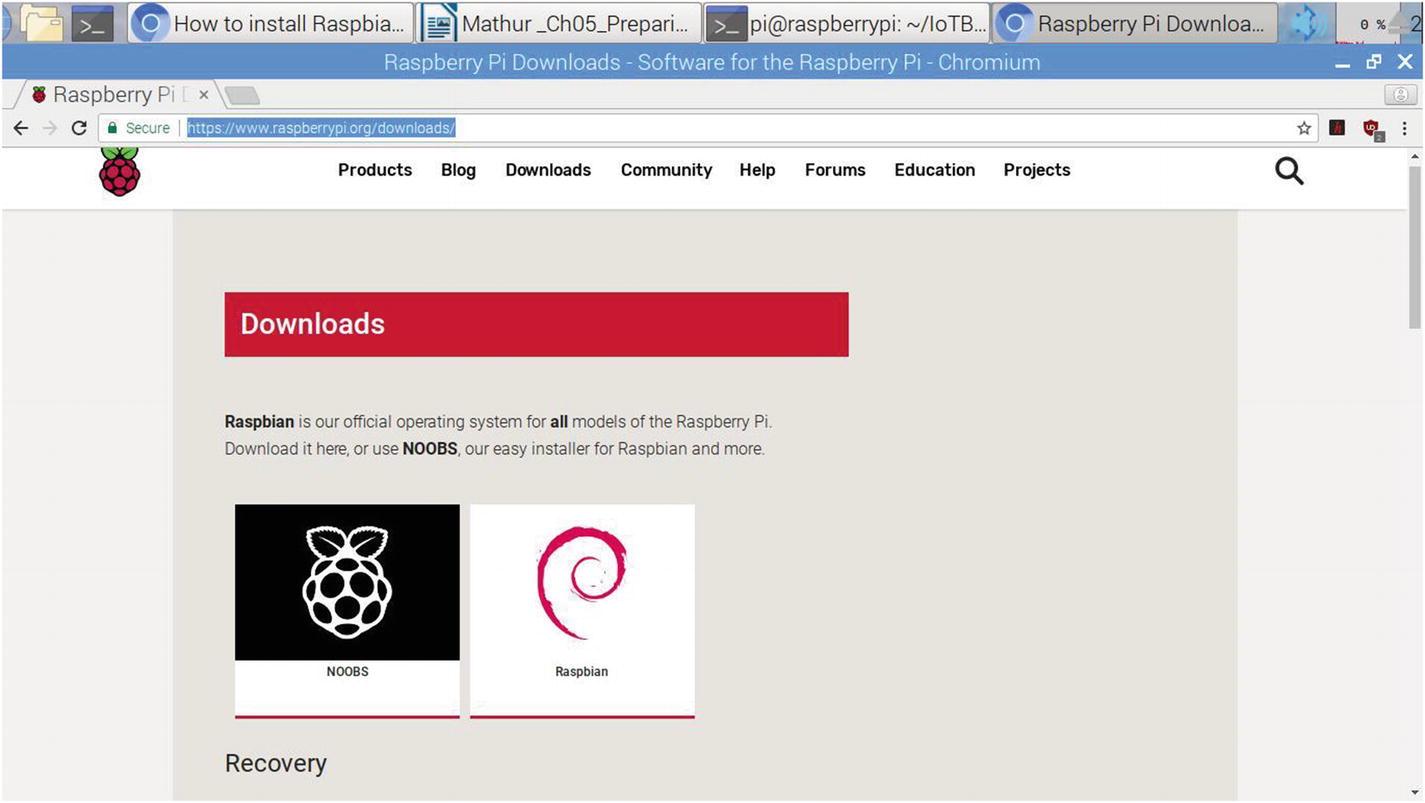
The first step to setting up your Raspberry Pi 3 Model B+ hardware is to decide on the operating system that you will use to run your applications. There are two popular operating systems available: Raspbian and Noobs. Noobs is used by people who are new to Raspberry Pi. You will be using the Linux version Raspbian, which is available from www.raspberrypi.org/downloads/. It can be seen in Figure 5-1, which shows the available operating system images for download from the official Raspberry Pi website.
Note that at this stage you have not booted up your Raspberry Pi 3 B+ as there is no operating system installed on its microSD card yet. A microSD card and microSD card reader or adapter come with the Raspberry Pi 3 B+ kit. If you do not have a microSD card, you can get one from the options on my website at www.pmauthor.com/raspbian/. For the installation of Raspbian, the base suggested microSD card size is 8GB. For Raspbian Lite image installations, Raspberrypi.org suggests at least 4GB. Do keep in mind that just the Raspberry Pi 3A+, 3B+, and Compute Module 3+ can boot from an SD card bigger than 256GB. This is because there was a bug in the SoC utilized on past models of Pi. Also remember to note the microSD card class to which your microSD card belongs because that decides the supported writing speed for it; a class 4 card will most likely write at 4MB/s, while a class 10 ought to accomplish 10 MB/s. Do note this does not mean a class 10 card will beat a class 4 card for general read/write performance, in light of the fact that frequently this write speed is accomplished at the expense of read speed and a substantial increase seek times to the microSD card operations. The microSD card that comes with your Raspberry Pi 3 B+ kit should be latest and should most probably be class 10, as is common now; however, if you get a lower class like 4, you can order a faster card of class 10 at www.pmauthor.com/raspbian/.
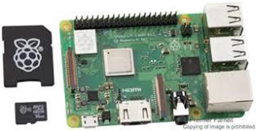
Of course your laptop must have a slot for reading and writing to microSD cards either directly or through an adapter. This is shown in Figure 5-2. Also, you will need a computer or a laptop that is running either Windows or MacOS in order to download this image and then format the SD card and install this image on to it. I will show you how to do this on a Windows system in this chapter.
Figure 5-2
The microSD card and microSD card adapter that comes with the official kit
Do not insert the microSD card adapter into the Raspberry Pi 3 B+ board yet because it is empty and not formatted with any operating system image written on top of it yet. You need to first download the Raspbian image by clicking the download section of the website. Once you do so, you will get the option to download the latest image of Raspbian for your use. As of the writing of this book, the there are three options for download, as shown in Figure 5-3.
Figure 5-3
Download options for Raspbian
The first option is the Raspbian Buster, which is the name of the Raspbian flavor available for the desktop and recommended software. The second option is only the desktop and the third is the Lite version, which does not have all the features needed for you to do extensive programming for your IoT applications. So you will use the first option, which provides all the components of the software necessary to get going. You can click the Torrent or zip file depending on the software that you use to unzip it. I used the zip file version. The zip file for the Buster flavor of Raspbian is approximately 2.3GB so it takes time to download depending on your internet connection speed.
Once you have this downloaded, you need to insert your microSD card reader into the computer/laptop from which you are installing the operating system onto the SD card slot. Since you are using Windows, you will need a disk imaging utility. The free utility that I use is Win32 Disk Imager. If you do not have it, you can download it from this page: www.pmauthor.com/raspbian/. Once you have installed the Win32 Disk Imager utility after downloading it from the website, you can open it by double-clicking its icon. It should look like the one in Figure 5-4.
Figure 5-4
Win32 Disk Imager
Click the browse icon shown in the figure and locate your unzipped image file where you downloaded it. After selecting the location of the image file, click the Device drop-down box on the right-hand side and select your microSD Card drive letter from it. The Write button on the dialog box will get enabled, so click it to write the image. The progress bar will show you when it is done; this should not take more than a few minutes. Once it is done, click the Exit button to eject the microSD card. You now have an image of the latest Raspbian OS written on your microSD card and ready to boot. Before you can boot, however, you need to set up the SBC physical wires on the board and then attach the microSD card to the Raspberry Pi 3 B+ board.
The second step to setting up the Raspberry Pi 3 Model B+ is to get its board wired as shown in Chapter 2 with photos of the GPIO pins and the various components of the SBC. You need to plug in the bare minimum to get started. First, you need an LED/LCD TV or a display. There are many available, but the ones I prefer and use on my projects are listed at www.pmauthor.com/raspbian/. If you have a spare TV, you can use the HDMI-to-HDMI cable to connect it from your TV to the HDMI port on the SBC. See Figures 5-5 and 5-6.
Figure 5-5
HDMI-to-HDMI cable
If you have a small 5-inch or 7-inch display, then you will have a different cable and you may not have an HDMI slot on the compact LCD/LED panel.
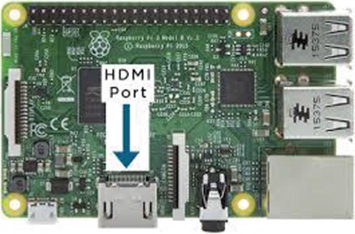
Figure 5-6
HDMI port on Raspberry Pi 3 B+
The connected Raspberry Pi will look like the one in Figure 5-7. Make sure you get the connections right and do not to leave them loose in the port on both sides (the TV display and the Raspberry Pi 3 b+) or your display will not show up. This is a common beginner problem; after you power on your Raspberry Pi, you don’t see the display coming up and you wonder what happened. It’s an easy mistake to fix because the HDMI ports on the Raspberry Pi are quite large so you can see if the wire is secured properly on to the board. Also, make sure you do not power on the Raspberry Pi 3 B+ when you are fixing the HDMI cable onto it; this is important both as a safety precaution and as an operational requirement. Sometimes, when you have a powered-on Raspberry Pi and you fix the HDMI cable into its HDMI port, the display won’t show up. In this case, restart the Raspberry Pi 3 B+ as there is no reboot button on this SBS.
There are two things I recommend doing before you finally boot up your Raspberry Pi. The first is to insert a USB mouse dongle into one of the four USB ports on the Raspberry Pi 3 B+ board. The second is to add another USB dongle for a wireless keyboard. These are essentials for you to control your SBC. You can see them connected to the SBC in Figure 5-7. Don’t worry if you do not have a wireless version of a mouse or a keyboard; the wired versions of the USB mouse and keyboards work pretty well. It’s just that the wired devices prove to be a bit too heavy for the SBC, which is very light and can move around if the wire of the mouse or keyboard shakes.
Figure 5-7
USB dongles connected to the SBC
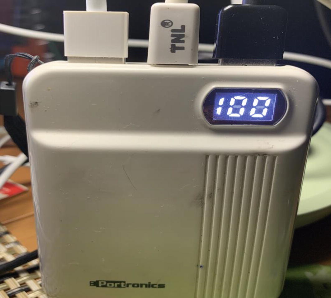
Next, to get your Raspberry Pi to boot up, you need to plug it into a power source. The wonderful thing about this small SBC is that it uses microUSB as its power source. This means that you can power it via a power bank as well by attaching a microUSB power cable to it. Why do you need a power bank? It provides a power backup so that it does not shut down when the power goes off. This is important if you live in a region of the world where power cuts are frequent. If your region has stable power, then you do not need to connect to a power bank and you can connect it to the power source through a power adapter charger. You can see my connection to a power bank in Figure 5-8.
Figure 5-8
Raspberry Pi 3 B+ power cord connected to a power bank
What you see in the image is a Portronics 10000mAH power bank. It provides power for commercial applications for a few hours. In one of our factory energy audit applications, we had to create a power bank backup with one power bank connected to another one in serial, the first one feeding into the another one, so that even if the power went off for a few hours, the Raspberry Pi energy audit applications running on it would not be affected. Sometimes you need to think out of the box to build commercial grade applications that can take power cuts in its stride.
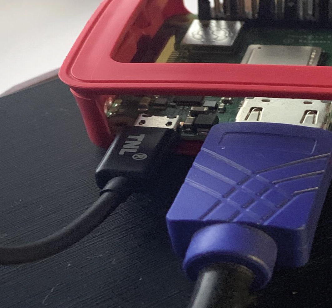
Now to bring your Raspberry Pi 3 B+ to life you just need to insert the microUSB side of the power cable into the power slot of the SBC, as shown in Figure 5-9. Please remember that if you have connected to a power source or a power bank and you are inserting the wire in the SBC, it will boot up in your hand. To prevent this, make sure the other end does not have power when you connect the microUSB to it.
Figure 5-9
microUSB and HDMI cables connected to Raspberry Pi 3 B+ SBC
Now you are ready to boot up your device, so go ahead and switch on the power to your power adapter, which is connect to microUSB power cable. You will see a green LED blink near the HDMI port slot and the connected LED/LCD monitor should show the booting up image you saw in Chapter 3. Now you just have the basic Raspberry Pi with the latest version of Raspbian installed onto it. Next you need the software to be installed in order to work with the IoT sensors and devices.
If you are running Raspbian (not the Lite version), Python version 2.7 is preinstalled with the Raspbian distribution image. However, if you want to use Python 3, it needs to be installed through the following Raspbian command line prompt. Needless to say, you need an internet connection either through a connected Ethernet cable or a Wi-Fi connection to your Raspberry Pi.
pi@raspberrypi:~ $ sudo apt-get install python3
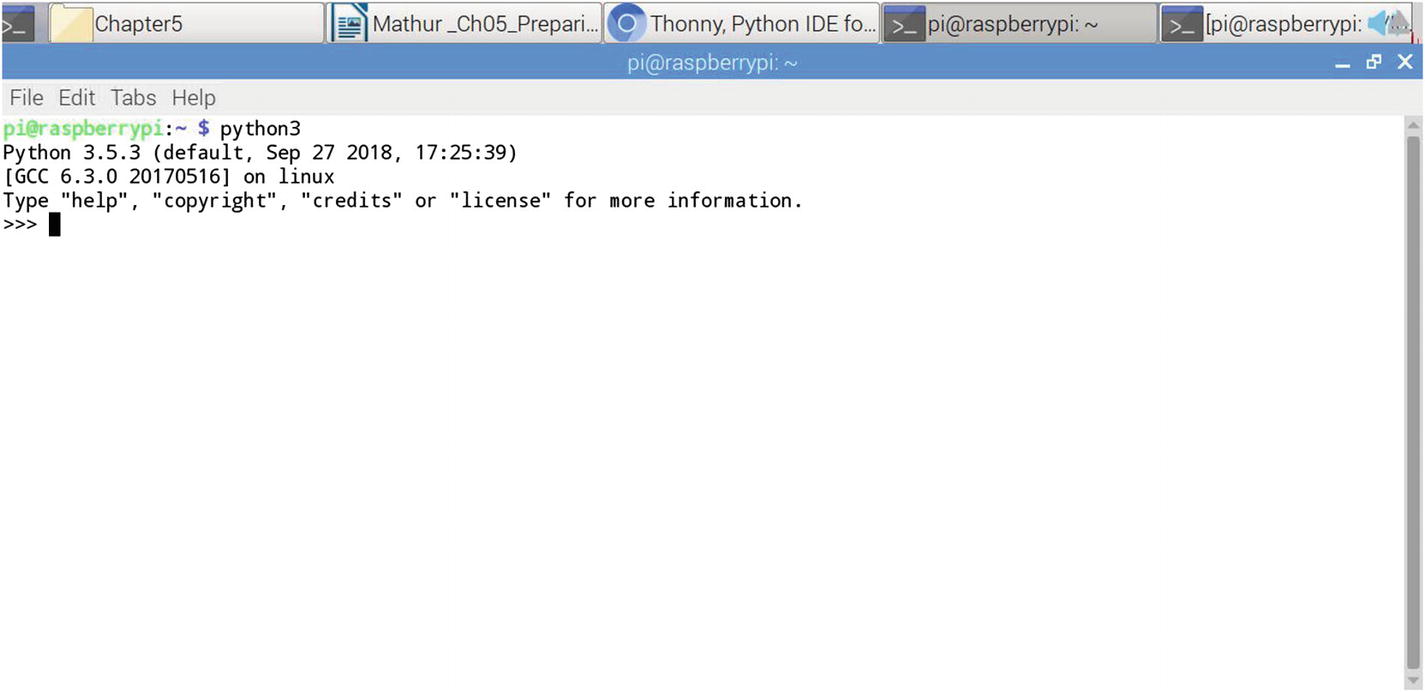
Test your Python 3 installation on the Raspbian by typing the command given in Figure 5-10.
Figure 5-10
Testing the Python 3 installation
Now that you have the required Python version installed and tested, you need an integrated development environment (IDE) to program on Raspbian. I recommend you use the Thonny IDE because it lets you compile programs and run them in a single place inside an editor. I have discussed the need and features in Chapter 3 so let’s get straight to the steps you need to install it on your Raspbian.
The Thonny IDE is free and comes preinstalled on most Raspbian OSes with Stretch program. If you do not find it in your installed programs, as you saw in Chapter 3, it can be downloaded from its website: https://thonny.org/. The good thing about this website is that it has a pictorial tutorial on its home page on how to use the IDE, which is pretty basic and simple. The installation can be done using the command in Listing 5-1.
(Reading database ... 149433 files and directories currently installed.)
Preparing to unpack .../python3-asttokens_1.1.13-1+rpt1_all.deb ...
Unpacking python3-asttokens (1.1.13-1+rpt1) ...
Preparing to unpack .../python3-thonny_3.1.0-1+rpt2_all.deb ...
Unpacking python3-thonny (3.1.0-1+rpt2) over (3.0.5-1+rpt1) ...
Processing triggers for mime-support (3.60) ...
Processing triggers for desktop-file-utils (0.23-1) ...
Processing triggers for man-db (2.7.6.1-2) ...
Setting up python3-asttokens (1.1.13-1+rpt1) ...
Processing triggers for gnome-menus (3.13.3-9) ...
Processing triggers for hicolor-icon-theme (0.15-1) ...
Setting up python3-thonny (3.1.0-1+rpt2) ...
pi@raspberrypi:~ $
Listing 5-1
Installing Thonny for Python 3
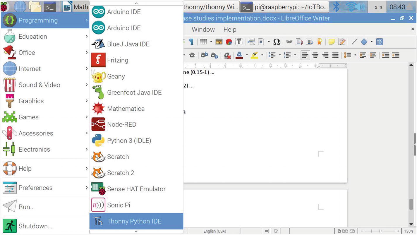
The Raspbian package for the Thonny IDE is downloaded from the archives of the raspberry.org official website and then processed and set up for use. If the installation is successful, you should see your IDE installed under the Programming menu in the Start bar, as shown in Figure 5-11.
Figure 5-11
Verifying the Thonny Python IDE installation
I discussed the verification part of the Thonny IDE in Chapter 3, so let’s move to the next step of installing the required Python libraries for use in the case studies. The following is a list of Python libraries that you will need. Remember to change tkinter to Tkinter (yes, capital T), as discussed in Chapter 3.
numpy is for operations on n-arrays and matrices in Python.
pandas is used for data wrangling. It was designed for quick and easy data manipulation, aggregation, and visualization.
Seaborn is for data visualization of statistical models through heatmaps and aggregrates.
scikit-learn provides a consistent interface for machine learning algorithms used in your programs.
Tkinter is for creating a graphical user interface for Python programs.
scipy contains modules for linear algebra, optimization, integration, and statistics.
matplotlib is for data visualization through various plots and graphs.
NLTK is a natural language toolkit, and it used for common tasks of symbolic and statistical natural language processing.
statsmodels is used to conduct data exploration through the use of various methods of estimation of statistical models and performing statistical assertions and analysis.
Now that you have seen the Python libraries that you need for the case studies, go ahead and install them. I created a script that does so on the Raspbian command line; see Figure 5-10. Please remember that the code is to install on Python 2.7; your need to change the script to add a 3 to pip and make it pip3 if you want to install all the libraries on Python 3.
Alert
If you use your own script for installing the Python libraries, make sure you use sudo before the pip install command, as shown in the script pipinstaller.run in Listing 5-2.
pi@raspberrypi:~/$ cat pipinstaller.run
sudo pip install numpy | tee /home/pi/numpy.log
sudo pip install pandas | tee /home/pi/pandas.log
sudo pip install seaborn | tee /home/pi/seaborn.log
sudo pip install sklearn | tee /home/pi/sklearn.log
sudo pip install tkinter | tee /home/pi/tkinter.log
sudo pip install scipy | tee /home/pi/scipy.log
sudo pip install nltk | tee /home/pi/nltk.log
sudo pip install statsmodels | tee /home/pi/statsmodels.log
pi@raspberrypi:~/
Listing 5-2
Raspbian Command Line Script to Install the Required Python Packages
You will notice that I appended sudo before every command and then piped the output to the command to log the output into a file for each of the Python libraries. So for sudo pip installscipy | tee /home/pi/scipy.log, the output is stored in a separate log file named scipy.log. It’s easier to be able to look at each of the log files separately and to debug and see if there were any errors during installation. You may ask why am I storing all these outputs in a log file and the simple answer is because on Raspbian 3 Model b+ it can take several hours for a package to install depending upon its size and the download speed of the Internet in your area. So keep in mind this important point before running the script and make sure you have power backup running for your Raspberry Pi system and display. Everything should have backup power before you attempt to run this script. The backup power for your monitor is equally important because the Raspberry Pi Model 3 B+ fails to show the screen sometimes if your monitor is switched off for some reason, like a power cut. The output of the script may look like Listing 5-3.
Requirement already satisfied: numpy in /usr/lib/python2.7/dist-packages
Requirement already satisfied: pandas in /usr/lib/python2.7/dist-packages
Requirement already satisfied: numpy>=1.7.0 in /usr/lib/python2.7/dist-packages (from pandas)
Requirement already satisfied: python-dateutil in /usr/lib/python2.7/dist-packages (from pandas)
Requirement already satisfied: pytz>=2011k in /usr/lib/python2.7/dist-packages (from pandas)
Requirement already satisfied: seaborn in /usr/lib/python2.7/dist-packages
Requirement already satisfied: sklearn in /usr/local/lib/python2.7/dist-packages
Requirement already satisfied: scikit-learn in /usr/lib/python2.7/dist-packages (from sklearn)
Collecting tkinter
Could not find a version that satisfies the requirement tkinter (from versions: )
No matching distribution found for tkinter
Requirement already satisfied: scipy in /usr/lib/python2.7/dist-packages
Requirement already satisfied: statsmodels in /usr/lib/python2.7/dist-packages
Listing 5-3
Output of the Pip Python Package Installer Script
In my case, as you can see from the installer log output, I had all the necessary libraries except for nltk, in which case it was downloaded and installed. To verify if there were any errors during setup of nltk library, the output of nltk.log file is shown in Listing 5-4.
So no errors were found in this file and the python nltk library was installed successfully. You may want to check all the other log files that were installed for you one by one, like scipy.log, statsmodels.log, etc. Now you have successfully installed all the required Python libraries.
Time Out for Testing
I asked you at the beginning of Chapter 3 to not execute any code and enjoy the execution of the IoT with machine learning along with Arduino. But here you are setting up all the infrastructure software and hardware that you need to get up and running for the case studies ahead.
However, before proceeding to the execution in the next chapter, I urge you to go back to Chapter 3 and execute all the code for testing your Python libraries given in Figure 3-3, the Hello world Python code that tests the installed libraries on your Raspbian. Figure 3-4 shows the output of the code on the Thonny IDE and you should get a similar output too. If not, you may have not installed your Python libraries correctly; you may need to go back and check your installation logs from Figure 5-11 to check where the error occurred. Then you should go ahead and execute the code for testing the Pandas dataframe in Figure 3-5, whose output should be similar to that shown in Figure 3-6 on the Thonny IDE. Further, you should test the small code in Figure 3-7 for the sklearn machine learning integrated library, the output of which appears in Figure 3-8 of Chapter 3. These are tests for basic libraries; however you could check the advanced libraries like tkinter, gpiozero, smtplib, pygame, psutil, platform, and time, which were used in the Python code of Chapter 3 via the Raspbian command line script given in Listing 5-5, the iotpypkgtest.run program. I showed a permission denied error that you may get on the command line the first time you execute it; it can be solved by changing the permissions using the chmod 700 command for the script.
pi@raspberrypi:~/$ ./iotpypkgtest.run
bash: ./iotpypkgtest.run: Permission denied
pi@raspberrypi:~/$ chmod 700 iotpypkgtest.run
pi@raspberrypi:~/$./iotpypkgtest.run
pi@raspberrypi:~/$
pi@raspberrypi:~/$ ls -l ∗.out
-rw-r--r-- 1 pi pi 0 Aug 17 23:19 gpiozero.out
-rw-r--r-- 1 pi pi 0 Aug 17 23:19 platform.out
-rw-r--r-- 1 pi pi 0 Aug 17 23:19 psutil.out
-rw-r--r-- 1 pi pi 0 Aug 17 23:19 pygame.out
-rw-r--r-- 1 pi pi 0 Aug 17 23:19 smtplib.out
-rw-r--r-- 1 pi pi 0 Aug 17 23:19 time.out
-rw-r--r-- 1 pi pi 111 Aug 17 23:19 tkinter.out
pi@raspberrypi:~/$
Listing 5-5
Script for Testing the Advanced Packages Installation
I deliberately used the command python -c ‘import tkinter’ in the script to create an error so that you can see in Listing 5-5 the rest of the files are of zero bytes; however, the tkinter.out file has 111 bytes written to it, signaling that there is some error there. You saw the reason for the error in Chapter 3; however, to reiterate, the tkinter library is used for GUI creation purposes such as window screens and buttons to manipulate the IoT devices and works with Python 3.x instead of Python 2.7. On your Raspbian command line, when you type just python, you are invoking the Python 2.7 interpreter; if you want to invoke the Python version 3 interpreter, you need to type python3 in the command line, like I have done in Listing 5-6.
pi@raspberrypi:~/$ python3 -c "import tkinter"
pi@raspberrypi:~/$
Listing 5-6
Successful Execution of tkinter on Python 3.x Intepretor
The error from the Python 2.7 command line is shown in Listing 5-7.
pi@raspberrypi:~/$ cat tkinter.out
Traceback (most recent call last):
File "<string>", line 1, in <module>
ImportError: No module named tkinter
pi@raspberrypi:~/$
Listing 5-7
Error from Python 2.7 Command Line
The error is not very intuitive but it does say there is no module named tkinter that this version of the interpreter recognizes. You may get a different error if there is a problem with any of the other Python library installations and that will need to be debugged by you separately. So far you have installed the basic libraries necessary for Python programs to run including sklearn for machine learning algorithms. However, for IoT to work through Raspberry Pi 3 B+ and Arduino Mega 4560, you need the advanced libraries from the following list:
gpiozero: Main library that enables communication between Python and the GPIO ports on Raspberry Pi 3 B+.
smtplib: Used to send email alerts from the Raspbian Linux-based OS.
pygame: Used to generate sounds in your Python programs.
psutil (process and system utilities): A cross-platform library for retrieving information on running processes and system utilization (CPU, memory, disks, network, sensors) in Python.
platform: Used to access the underlying platform’s data, such as hardware, OS, and interpreter version information.
time: Python has defined a package named time which allows you to handle various operations regarding time and its conversions and representations, which find use in your applications for storing the timestamp of an event through your IoT devices.
The gpiozero is the main python package I use on Raspberry Pi 3 B+, which has been tested and run successfully on commercial applications for my clients, so I recommend using this package for communicating with IoT devices. What is the use of having an application that does monitoring and alerting but does not communicate in real time to the required people? For this you need the smtplib python library. Configuring a SMTP server on your Raspberry Pi 3 B+ is beyond the scope of this book so I will not cover this part. However, once you have it configured, it is easy to send an email using the machinemon applications given in Chapter 3. The psutil and platform Python packages are used to get data from the underlying hardware of Raspberry Pi 3 B+ such as CPU percentage, temperature, memory, disk space, etc. To create a successful commercial application, you need to store a timestamp of every event that occurs during monitoring through IoT devices and for this the time Python package comes in handy.
You now know about the advanced packages that are to be used for IoT, so go ahead and install them using a script named iotpypackagesinstall.run and a test named iotpypackages.run, shown in Listings 5-8 and 5-9, respectively.
sudo pip install gpiozero | tee gpiozero.log
sudo pip install pygame | tee pygame.log
sudo pip install psutil | tee psutil.log
pi@raspberrypi:~$ ./iotpypackagesinstall.run
Requirement already satisfied: gpiozero in /usr/lib/python2.7/dist-packages
Requirement already satisfied: pygame in /usr/lib/python2.7/dist-packages
Requirement already satisfied: psutil in /usr/lib/python2.7/dist-packages
As you can see from the test script output in Listing 5-9, all the files are 0 bytes except for tkinter.out. So the advanced packages have been installed successfully. If you find any issues during these Python library installations, you can write to me through the technical forums at www.pmauthor.com/raspbian/ and I will try to help resolve your queries.
So far you have successfully set up your Raspberry Pi 3 B+ and also Python with its required packages and tested them through scripts in this chapter and Chapter 3. Now you must install the Arduino IDE to communicate with the Arduino Mega 4560 and create a SQLite3 database where your IoT applications can to store data. After installing the Arduino IDE, you will need to test communication between Raspberry Pi and Arduino using a serial cable. You will look at the detailed steps of setting up the hardware of the Arduino Mega 4560 to Raspberry Pi 3 B+ in the next steps.
Determining Bit Size
Before you proceed to installing the Arduino IDE, you need to know whether your Raspberry Pi is 32-bit or 64-bit. For this, there are two useful commands that are given in Listing 5-10, which provide the bash bit version.
> which bash
/bin/bash
> file /bin/bash
/bin/bash: ELF 32-bit LSB executable, ARM, version 1 (SYSV) ...
Listing 5-10
Finding Out the Bit Version of Your Raspberry Pi
My Raspberry Pi 3 B+ has a 32 bit bash executable. This is not a very definitive way of determining your bit version, but it is most unlikely that a 32-bit bash has been compiled on a 64-bit processor by the hardware manufacturer. Further, to confirm, you can use the uname command shown in Listing 5-11, which shows that I am running a Raspberry Pi Linux variant on an ARMv7 processor.
pi@raspberrypi:~/$ uname -a
Linux raspberrypi 4.14.98-v7+ #1200 SMP Tue Feb 12 20:27:48 GMT 2019 armv7l GNU/Linux
Listing 5-11
Command for Confirming the Processor Information
Even this does not clearly say the width bit of the processor. It is important to know this information because you don’t want to install the wrong Arduino bit IDE and mess up your Raspbian installation. So you can use a program known as lshw, which you can install using the command shown in Listing 5-12.
pi@raspberrypi:~/$ sudo apt-get install lshw
Reading package lists... Done
Building dependency tree
Reading state information... Done
The following packages were automatically installed and are no longer required:
(Reading database ... 149467 files and directories currently installed.)
Preparing to unpack .../libpci3_1%3a3.5.2-1_armhf.deb ...
Unpacking libpci3:armhf (1:3.5.2-1) ...
Selecting previously unselected package pciutils.
Preparing to unpack .../pciutils_1%3a3.5.2-1_armhf.deb ...
Unpacking pciutils (1:3.5.2-1) ...
Selecting previously unselected package lshw.
Preparing to unpack .../lshw_02.18-0.1_armhf.deb ...
Unpacking lshw (02.18-0.1) ...
Setting up lshw (02.18-0.1) ...
Processing triggers for libc-bin (2.24-11+deb9u3) ...
Processing triggers for man-db (2.7.6.1-2) ...
Setting up libpci3:armhf (1:3.5.2-1) ...
Setting up pciutils (1:3.5.2-1) ...
Processing triggers for libc-bin (2.24-11+deb9u3) …
Listing 5-12
Installing the lshw Utility to Find Out the Processor Bit
Now that you have this utility installed, you can type the command lshw. The output in Listing 5-13 clearly gives shows the width bit as 32-bit for my processor.
While this command gives an awful lot of information about the hardware, the information we are interested in is given in the sixth line of the command output: width: 32 bits. This confirms in a definitive manner that my Raspberry Pi 3 B+ is running on a 32-bit processor.
Installing the Arduino IDE
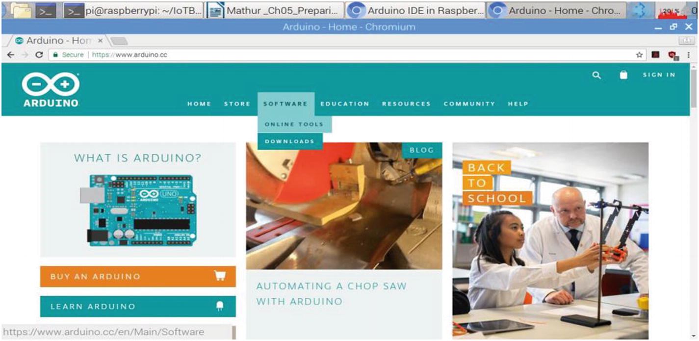
Since you know your processor bit width, you can move to the actual installation of the Arduino IDE, which can be done in two ways. One way is to go to www.arduino.cc and click Software ➤ Downloads, as shown in Figure 5-12.
Now scroll down to the Arduino IDE download section shown in Figure 5-13 and choose the operating system with the corresponding bit (32 or 64) for download.
Figure 5-13
Download the Arduino IDE
As you can see, there are various options in the blue bar on the right-hand side of the page. Linux has four options: Linux 32 bits, Linux 64 bit, Linux ARM 32 bits, and Linux ARM 64 bits. The uname and lshw commands showed that I am running Linux on an ARM v7 processor with a width bit of 32 bits, so I select Linux ARM 32 bits for download in my case. If you have a 64-bit processor, you need to download the Linux ARM 64-bit IDE. Click the Just Download button on the next page if you do not want to contribute a small donation towards Arduino development.
After the download ends, follow the steps given in Figure 5-14 by clicking Show in Folder option in your browser.
Figure 5-14
Click the Show in Folder option to see the downloaded file
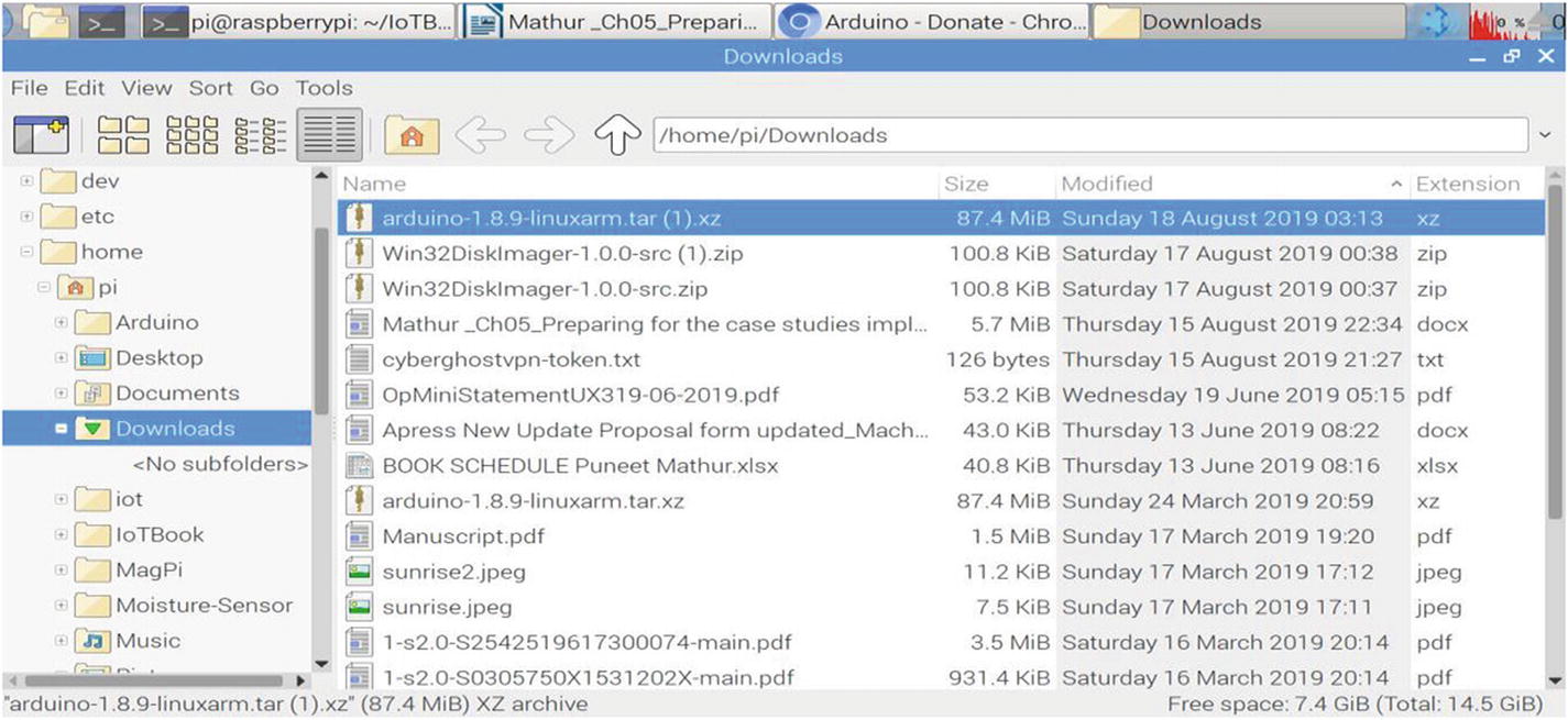
After this, the Raspbian GUI File Explorer will open the Downloads folder where the Arduino compressed file has been downloaded, as shown in Figure 5-15.
Figure 5-15
Downloads folder with the *.xz compressed file
You need to extract the tar file from inside the ∗.xz extension file, as shown in Figure 5-16. Right-click the file to select and left-click the Extract Here menu option.
Figure 5-16
The Extract Here option for the *.xz file
When you click the Extract Here option, you will see a dialog box that will show you the progress of your file extraction process. See Figure 5-17.
Figure 5-17
Extraction in progress for the *.xz file
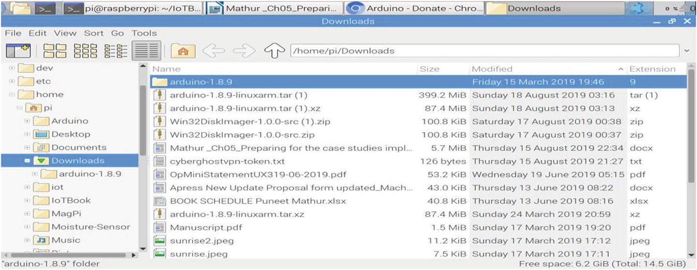
Once you have this extracted, you will be able to see a new file created in the Downloads folder with the same name as the ∗.xz file but now with a ∗.tar extension. Right-click this file again and select the Extract Here option from the dropdown menu once again, as shown in Figure 5-18.
Figure 5-18
Extraction of the tar file
After the extraction process is complete, you will now see a new folder created, as shown in Figure 5-19.
Figure 5-19
New Arduino folder after extraction
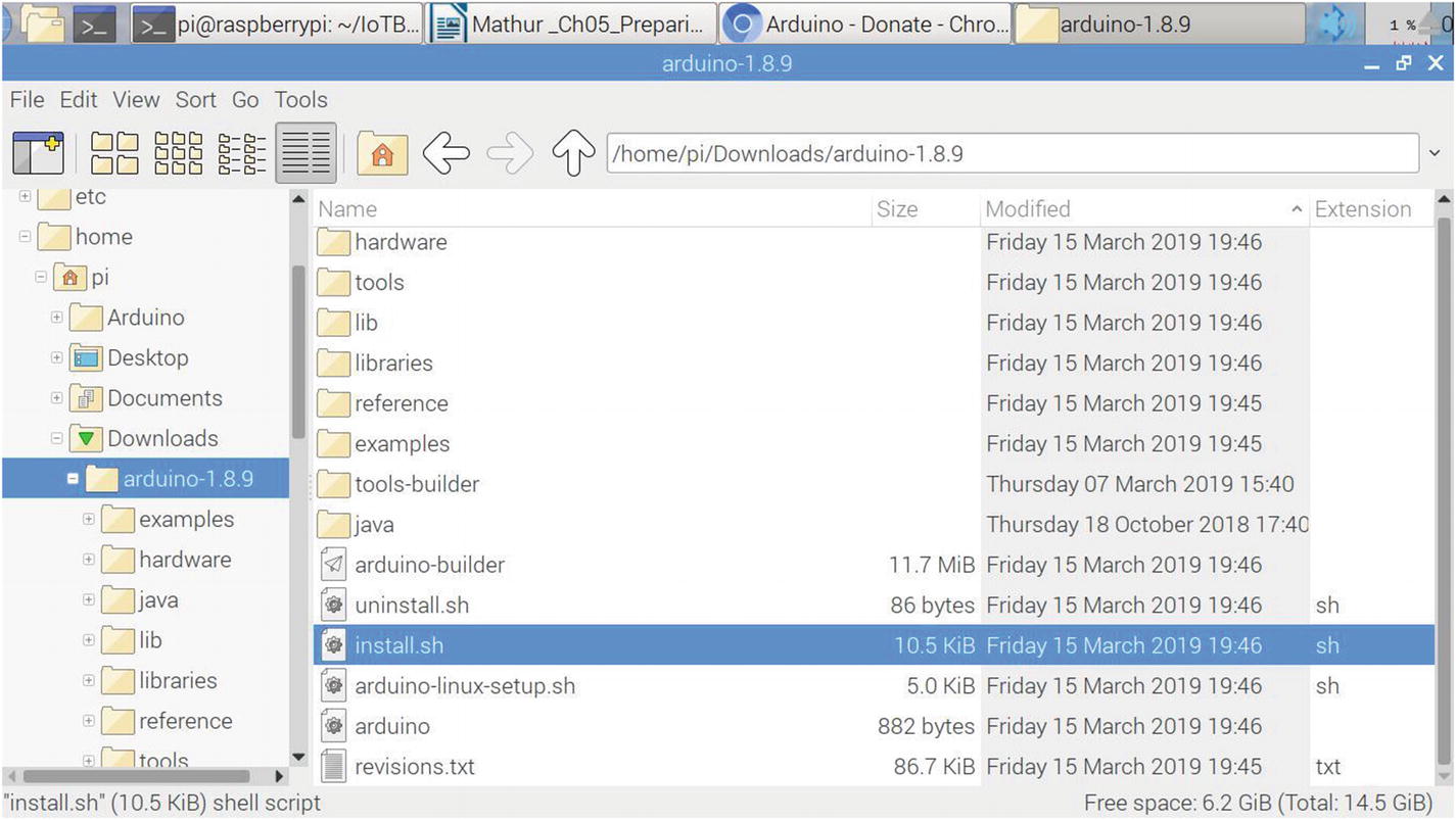
You can go into the folder by double-clicking it, as shown in Figure 5-20. You will see a file named install.sh. Double-click this file and the Arduino IDE will be installed on your system.
Figure 5-20
Running the install.sh file to finish the installation
The second, easier method to install the Arduino IDE just involves executing three commands:
sudo apt-get update
sudo apt-get upgrade
sudo apt-get install arduino
Although the command line method of installing the Arduino IDE is much simpler and has lot less steps, some people like the GUI more than the command line, so I have shown both the methods and leave it up to you on how you want to install it. Now you are at the data storage step in your setup, that of installing a SQLite3 database on Raspbian.
Installing SQLite3 Database
SQLite3 is a free database that you are going to use easily to create and use a database in your applications for storage. Although SQLite3 is not a full-featured database, it supports a large set of the SQL standard and is great for application development that need a simple database engine to plug into applications. SQLite3 is very popular with smartphone developers. The environment of the Raspberry Pi is also a mobile environment where we take it on the field, in factories, in agricultural fields, or near mobile towers to gather data through IoT sensors and store it in this compact, robust database. Please remember that you can’t use this database for applications that require high security features like built-in user management. So use it wherever there is no such security requirement. You can configure PostgreSQL or any other Linux database like MySQL on Raspbian but that is beyond the scope of this book since we are developing only PoC-grade code.
Use the following script to install Sqlite3 onto the Raspbian OS:
sudo apt-get update
sudo apt-get upgrade
sudo apt-get install sqlite3
sqlite3 <firstdb.db>
SQLite version 3.8.7.1 2014-10-29 13:59:56
Enter ".help" for usage hints.
sqlite>
You can also install SQLite3 in the manner I showed you for the GUI installation for the Arduino IDE from the official website of the SQLite organization at www.sqlite.org/download.html.
Now you’ve come to the last step of installing the Modbus interface device, the single phase meter, onto the Arduino.
Disclaimer
Before proceeding further, I would like to warn you of the risk associated with using this Modbus device. The energy meter is an electrical appliance and carries the risk of short-circuiting if not connected properly. It can also be dangerous to human life if not used as per its instruction manual. It can also burn and damage your Raspberry Pi and Arduino boards if wrong connections are made. So if you are not comfortable with electric connections, I strongly advise you to not use this device or to get expert help from a local electrical technician to make the proper connections. Neither I nor the publisher can be held responsible in any way whatsoever for any kind of damages, either material or to life. User discretion is highly advised.
The additional devices that you will be using to set up the energy meter are shown in Figures 5-21 through 5-23:
1.
Schneider Electric Conzerv EM6400 Series Power Meter
Figure 5-21
Conzerv EM6400 Energy Meter
2.
5V RS485 to TTL Signal Mutual Conversion Module for Arduino Overvoltage Protection with Signal Indicator
Figure 5-22
5V RS485 to TTL Signal Mutual Conversion Module for Arduino
Figure 5-23
Connected 5V Modbus Conversion Module
Let’s now connect the wires between the Arduino Mega 256 and the 5V RS485 Modbus Conversion Module. I have shown the wires attached to the Modbus Conversion Module in the Arduino Mega 2560.
In order to connect the Modbus Conversion Module to Arduino, you need to first understand the layout of the Arduino Mega 2560 PCB, which is shown in Figure 5-24. Notice in the diagram that the upper pins pertain to communication and the GPIO pins. The right side of the board has the data pins and the bottom part of the board has the power and analog pins. This board is very different from the Arduino Uno board because it is used for controlling multiple slaves and is used in industrial applications. This is why there are so many data pins in the PCB layout.
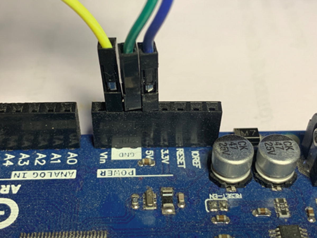
Now connect the Modbus Conversion Module to the Arduino Mega board. You have to connect three pins to the power area of the board, which is near the power controller on the bottom left-hand side of the layout diagram in Figure 5-24. The left-most dark blue pin gets connected to the pin that has 5V written under it. The next green wire is connected to the immediate next pin marked as GND. Ignore the yellow wire on the left of Figure 5-24; you don’t need it for your setup. You can see this in Figure 5-24—the three pins connected to the power section of the Arduino Mega board. Please remember these are male jumper wires that you need because the Arduino Mega board only has holes and not pins like the Raspberry Pi GPIO setup.
Figure 5-24
Modbus Conversion Module wire connections to Arduino Mega board
The wires on the other end have to be female jumper wires because the Modbus Conversion Module has pins to put the wires into. So you should have two male-to-female jumper wires for this connection. Connect the other end of these two wires to the Modbus Conversion Module pins marked as VCC and GND (VCC is the 5V power wire and GND is the grounding of the circuit). You can refer to Figure 5-25.
Figure 5-25
Power and ground connections to the Modbus Conversion Module
The 5V dark blue wire connected on Arduino connects to the VCC pin marked on the Modbus Conversion Module. The GND green wire pin on the Arduino board connects to GND on the Modbus Conversion Module PCB.
Now one part of your Modbus Conversion Module is connected to the Arduino board. You need to connect the other end to the GPIO pins section of the Arduino board or the communication side for a total of four pins. See Figure 5-26. On the Arduino board
Figure 5-26
Connections to the PWM and communications side of Arduino Mega board
As you can see, there are two pins on the left-hand side of the board named PWM connected to pins numbered 3 and 2, which are adjacent to each other. The next two pins are connected to the communications pins 18 and 19, which are marked as TX1 and RX1, respectively, on the Arduino Mega board. Once you have this in place, you need to connect the other end of the four pins in the following manner. Pin 1 connected on the Arduino board to pin number 3 of PWM needs to connect to the pin marked DE on the Modbus Conversion Module pin. Pin 2 connected on the Arduino board to pin number 2 of PWM needs to connect to the pin marked RE in the middle of the Modbus Conversion Module. Similarly, pin 3 connected on the Arduino board to pin number 18 in Figure 5-27 needs to connect to the pin marked DI on the Modbus Conversion Module. The fourth pin connected to pin number 19 on the Arduino board should be connected to the pin marked RO on the Modbus Conversion Module. This completes the wiring process for the Modbus Conversion Module to the Arduino Mega board. You can check your connections against Figure 5-27.
Figure 5-27
Wiring to the Modbus Conversion Module communication and PWM pins
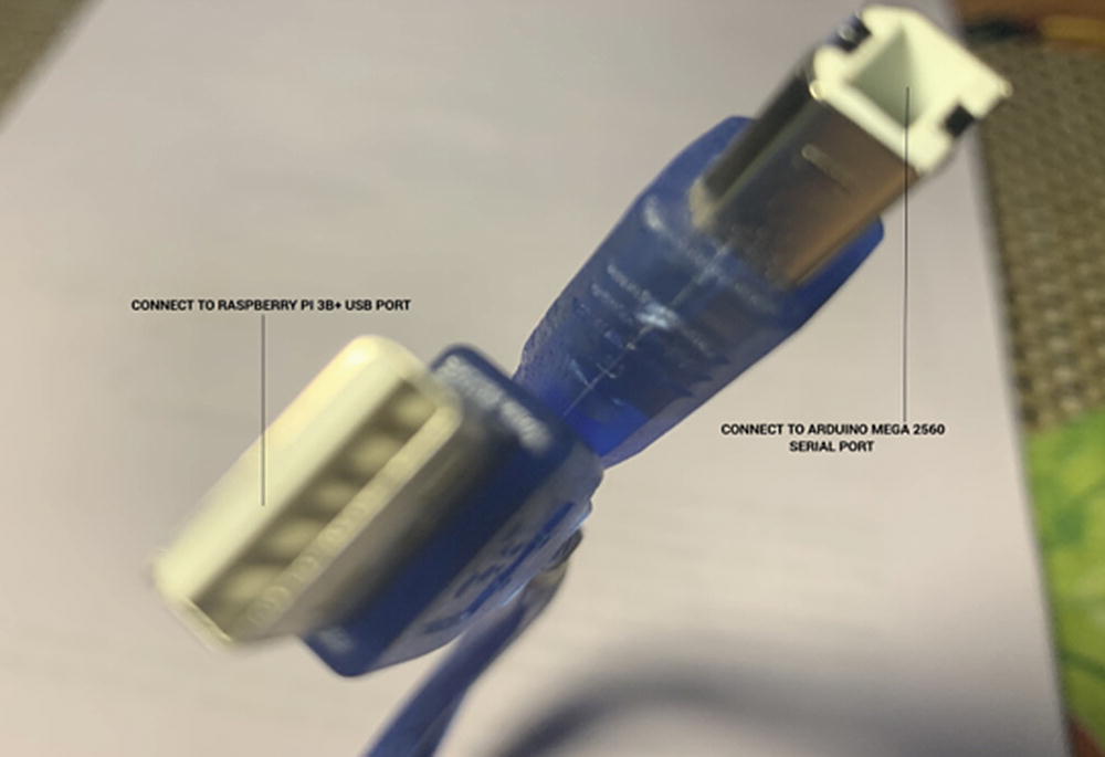
Now you are ready for the next step: to connect your Arduino module to the Raspberry Pi board. For this, you need to connect a serial USB wire from the serial USB port of the Raspberry Pi 3 B+ board to the Arduino Mega 2560 board. The wire is shown in Figure 5-28 for clarity.
Figure 5-28
USB serial cable to connect the Arduino Mega 2560 with the Raspberry Pi 3 B+
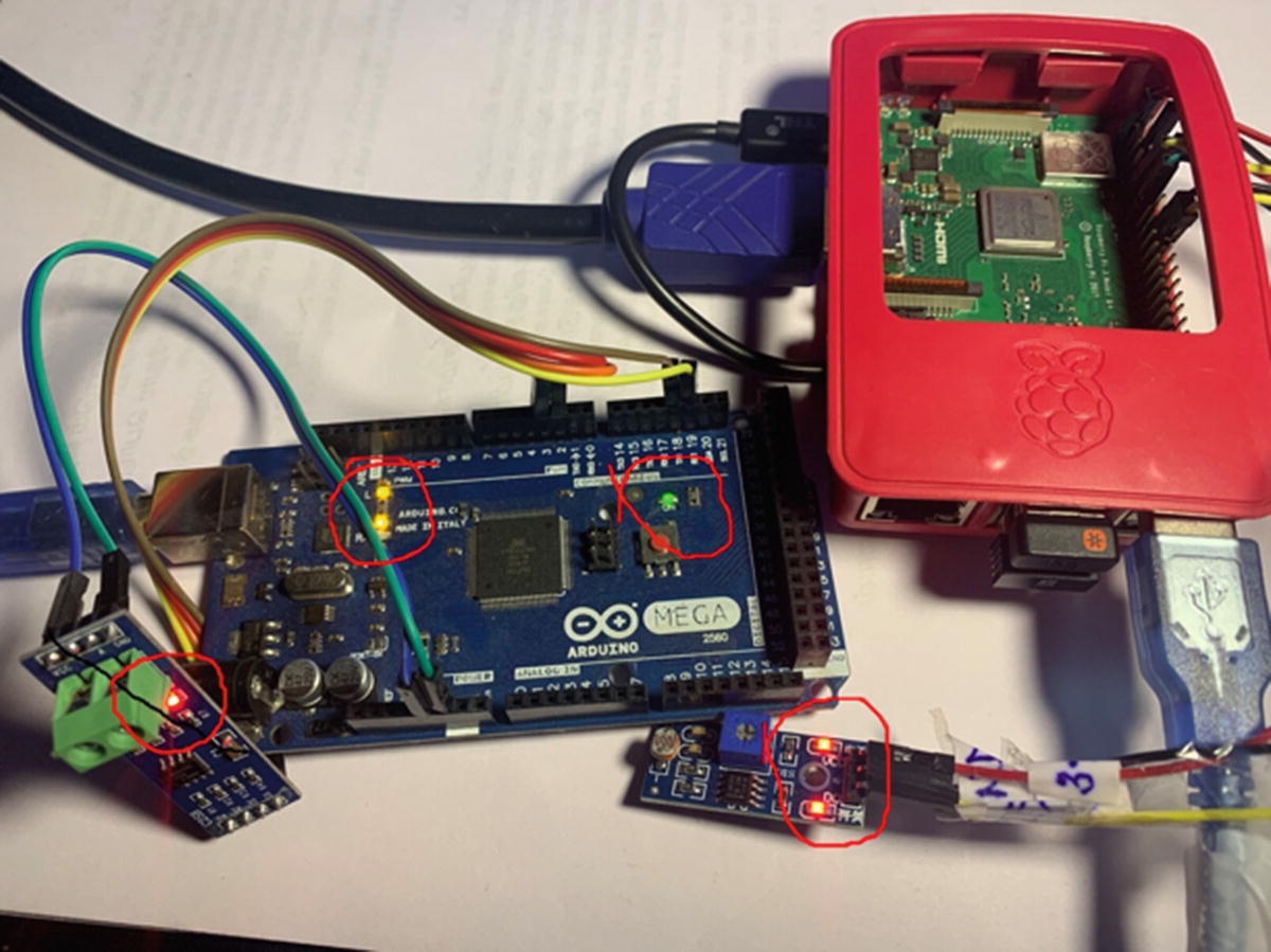
Now you are finally ready to power on your complete system. The Arduino does not need a separate power cable, although it has a slot for it on the board. The serial cable powers on the Arduino Board because it is a slave of the Raspberry Pi 3 B+ board. When you power on the Raspberry Pi 3 B+, you should see LED lights on the Modbus Conversion Module and the Arduino Mega 2560 board. This signals preliminarily that your connections are successful. This can be seen in Figure 5-29.
Figure 5-29
Final power on
If the board or the module does not light up, you should check your connections again, especially the ones supplying power to the module or the Arduino board. Now go ahead and run the Arduino Hello world program from Chapter 3 to confirm the serial communication between the Arduino Mega slave and Raspberry Pi 3 B+ master.
Summary
This chapter was about preparing your setup for the case studies implementation. You are now fully configured by setting up the Raspbian OS on the Raspberry Pi 3 Model B+ and downloading it from the www.raspberrypi.org download options. You used the microSD card and microSD card adapter to get the OS. Then you used the Win32 Disk Manager to unpack and extract the package. After this, you used the HDMI-to-HDMI cable in order to connect the Raspberry Pi to a TV monitor. You used USB dongles to connect a keyboard and mouse to the SBC. After this, you connected the Raspberry Pi 3 B+ power cord to a power bank so that its power connection would be failproof in case of a power outage.
You then installed Python and tested it on Raspbian. Next you installed and verified the Thonny Python IDE. You then ran a Raspbian command line script to install the required Python packages
You ran a script to test the installation of the Python advanced packages and to check for errors. You installed the tkinter package on Python for a GUI implementation and then successfully executed tkinter on the Python 3.x interpreter. After this, you ran the iotpypackages.run Raspbian script to install the IoT Python packages on Raspbian.
After this, you finished installing the Arduino IDE by running the install.sh file. You installed a SQLite3 database for storing data from IoT sensors. After this, you installed the Modbus interface device, the single phase meter, onto the Arduino. You configured and connected the three devices, the Schneider Electric Conzerv EM6400 Series Power Meter, the 5V RS485 to TTL Signal Mutual Conversion Module for Arduino Overvoltage Protection with Signal Indicator, and the 5V Modbus Converter Module. After this, you made the Modbus converter wire connections to the Arduino Mega board and connections to the PWM and communications side of the Arduino Mega board. You wired the Modbus Conversion Module communication and PWM pins through the USB serial cable to connect the Arduino Mega 2560 with Raspberry Pi 3 B+. After this, you performed the final power on for your complete system.
With this you come to the end of setting up your system, including the hardware and software. You can now proceed with the case studies.