
WHAT YOU WILL LEARN IN THIS CHAPTER
How to use an STL list container and an STL/CLR list container to store sketch data
How to implement drawing a sketch in the MFC and CLR versions of Sketcher
How to implement scrolling in a view in MFC Sketcher
How to create a context menu at the cursor
How to highlight the element nearest the cursor to provide feedback to the user for moving and deleting elements
How to program the mouse to move and delete elements
In this chapter, you'll extend the MFC version of Sketcher to make the document view more flexible, introducing several new techniques in the process. You'll also extend the MFC and CLR versions of Sketcher to store elements in an object that encapsulates a complete sketch.
The document in the Sketcher application needs to be able to store a sketch consisting of an arbitrary collection of lines, rectangles, circles, and curves in any sequence, and an excellent vehicle for handling this is a list. Using a list will also enable you to change an element's position in the list or to delete an element easily if it becomes necessary to do so. Because all the element classes that you've defined include the capability for the objects to draw themselves, the user will be able to a draw a sketch easily by stepping through the list.
You can define an STL list<CElement*> container that stores pointers to instances of the shape classes that make up a sketch. You just need to add the list declaration as a new member in the CSketcherDoc class definition. You also need a member function to add an element to the list, and AddElement() is a good, if unoriginal, name for this:
// SketcherDoc.h : interface of the CSketcherDoc class // #pragma once#include <list>#include "Elements.h"#include "SketcherConstants.h" class CSketcherDoc: public CDocument { protected: // create from serialization only CSketcherDoc(); DECLARE_DYNCREATE(CSketcherDoc) // Attributes public: // Operations public: unsigned int GetElementType() const // Get the element type { return m_Element; } COLORREF GetElementColor() const // Get the element color { return m_Color; }void AddElement(CElement* pElement) // Add an element to the list{ m_ElementList.push_back(pElement); }// Rest of the class as before... protected: ElementType m_Element; // Current element type COLORREF m_Color; // Current drawing colorstd::list<CElement*> m_ElementList; // List of elements in the sketch// Rest of the class as before...};
The CSketcherDoc class now refers to the CElement class, so there is an #include directive for Elements.h in SketcherDoc.h. There is also one for the list header because you are using the STL list<> template.
You create shape objects on the heap, so you can just pass a pointer to the AddElement() function. Because all this function does is add an element, you have put the implementation of AddElement() in the class definition. Adding an element to the list requires only one statement, which calls the push_back() member function. That's all you need to create the document, but you still have to consider what happens when a document is closed. You must ensure that the list of pointers and all the elements they point to are destroyed properly. To do this, you need to add code to the destructor for CSketcherDoc objects.
In the destructor, you'll first go through the list deleting the element pointed to by each entry. After that is complete, you must delete the pointers from the list. The code to do this is as follows:
CSketcherDoc::~CSketcherDoc(void)
{
  // Delete the element pointed to by each list entry
  for(auto iter = m_ElementList.begin() ; iter != m_ElementList.end() ; ++iter)
    delete *iter;

   m_ElementList.clear();   // Finally delete all pointers
}
You should add this code to the definition of the destructor in SketcherDoc.cpp. You can go directly to the code for the destructor through the Class View.
The for loop iterates over all the elements in the list. The auto keyword ensures the correct type is specified for the iterator iter. When the for loop ends, you call the clear() function for the list to remove all the pointers from the list.
Because the document owns the list of elements and the list is protected, you can't use it directly from the view. The OnDraw() member of the view does need to be able to call the Draw() member for each of the elements in the list, though, so you need to consider how best to arrange this. One possibility is to make some const iterators for the m_ElementList member of the document class available. This will allow the view class object to call the Draw() function for each element, but will prevent the list from being changed. You can add two more functions to the CSketcherDoc class definition to provide for this:
class CSketcherDoc: public CDocument
{

// Rest of the class as before...

// Operations
public:
   unsigned int GetElementType() const // Get the element type
      { return m_Element; }
   COLORREF GetElementColor() const    // Get the element color
      { return m_Color; }
   void AddElement(CElement* pElement) // Add an element to the list
      { m_ElementList.AddTail(pElement); }
   std::list<CElement*>::const_iterator begin() const // Get list begin iterator
                   { return m_ElementList.begin(); }
   std::list<CElement*>::const_iterator end() const   // Get list end iterator
                   { return m_ElementList.end(); }

// Rest of the class as before...

};
The begin() function returns an iterator that points to the first element in the list, and the end() function returns an iterator that points to one past the last element in the list. The iterator type is defined in the list<> class template as const_iterator, but because the iterator type is specific to a particular instance of the template, you must qualify the type name with the list instance type.
By using the two functions you have added to the document class, the OnDraw() function for the view will be able to iterate through the list, calling the Draw() function for each element. This implementation of OnDraw()is as follows:
void CSketcherView::OnDraw(CDC* pDC)
{
   CSketcherDoc* pDoc = GetDocument();
   ASSERT_VALID(pDoc);
   if(!pDoc)
     return;

  CElement* pElement(nullptr);
  for(auto iter = pDoc->begin() ; iter != pDoc->end() ; ++iter)
  {
    pElement = *iter;
    if(pDC->RectVisible(pElement->GetBoundRect())) // If the element is visible
         pElement->Draw(pDC);                      // ...draw it
  }
}

Frequently, when a WM_PAINT message is sent to your program, only part of the window needs to be redrawn. When Windows sends the WM_PAINT message to a window, it also defines an area in the client area of the window, and only this area needs to be redrawn. The CDC class provides a member function, RectVisible(), which determines whether a rectangle you supply to it as an argument overlaps the area that Windows requires to be redrawn. Here, you use this function to make sure that you draw only the elements that are in the area Windows wants redrawn, thus improving the performance of the application.
You use the begin() and end() members of the document object in the for loop to iterate over all the elements in the list. The auto keyword determines the type of iter appropriately. Within the loop, you dereference iter and store it in the pElement variable. You retrieve the bounding rectangle for each element using the GetBoundRect() member of the object, and pass it to the RectVisible() function in the if statement. If the value returned by RectVisible() is true, you call the Draw() function for the current element pointed to by pElement. As a result, only elements that overlap the area that Windows has identified as invalid are drawn. Drawing on the screen is a relatively expensive operation in terms of time, so checking for just the elements that need to be redrawn, rather than drawing everything each time, improves performance considerably.
The last thing you need to do to have a working document in our program is to add the code to the OnLButtonUp() handler in the CSketcherView class to add the temporary element to the document:
void CSketcherView::OnLButtonUp(UINT nFlags, CPoint point)
{
   if(this == GetCapture())
      ReleaseCapture();      // Stop capturing mouse messages

   // If there is an element, add it to the document
   if(m_pTempElement)
   {
      GetDocument()->AddElement(m_pTempElement);
      InvalidateRect(nullptr);  // Redraw the current window
      m_pTempElement = nullptr; // Reset the element pointer
   }
}
Of course, you must check that there really is an element before you add it to the document. The user might just have clicked the left mouse button without moving the mouse. After adding the element to the list in the document, you call InvalidateRect() to get the client area for the current view redrawn. The argument of 0 invalidates the whole of the client area in the view. Because of the way the rubber-banding process works, some elements may not be displayed properly if you don't do this. If you draw a horizontal line, for instance, and then rubber-band a rectangle with the same color so that its top or bottom edge overlaps the line, the overlapped bit of line disappears. This is because the edge being drawn is XORed with the line underneath, so you get the background color back. You also reset the pointer m_pTempElement to avoid confusion when another element is created. Note that the statement deleting m_pTempElement has been removed.
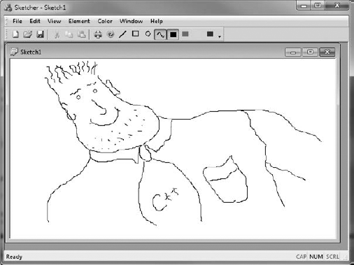
After saving all the modified files, you can build the latest version of Sketcher and execute it. You'll now be able to produce art such as "The Happy Programmer," shown in Figure 17-1.
The program is now working more realistically. It stores a pointer to each element in the document object, so they're all automatically redrawn as necessary. The program also does a proper cleanup of the document data when it's deleted.
There are still some limitations in the program that you can address. For instance:
You can open another view window by using the Window

You can draw only in the client area you can see. It would be nice to be able to scroll the view and draw over a bigger area.
You can't delete an element, so if you make a mistake, you either live with it or start over with a new document.
These are all quite serious deficiencies that, together, make the program fairly useless as it stands. You'll overcome all of them before the end of this chapter.
The first item that you can try to fix is the updating of all the document windows that are displayed when an element is drawn. The problem arises because only the view in which an element is drawn knows about the new element. Each view is acting independently of the others, and there is no communication between them. You need to arrange for any view that adds an element to the document to let all the other views know about it, and they need to take the appropriate action.
The document class conveniently contains a function, UpdateAllViews(), to help with this particular problem. This function essentially provides a means for the document to send a message to all its views. You just need to call it from the OnLButtonUp() function in the CSketcherView class whenever you have added a new element to the document:
void CSketcherView::OnLButtonUp(UINT nFlags, CPoint point)
{
if(this == GetCapture())
ReleaseCapture(); // Stop capturing mouse messages
// If there is an element, add it to the document
if(m_pTempElement)
{
GetDocument()->AddElement(m_pTempElement);
GetDocument()->UpdateAllViews(nullptr, 0, m_pTempElement); // Tell the views
m_pTempElement = nullptr; // Reset the element pointer
}
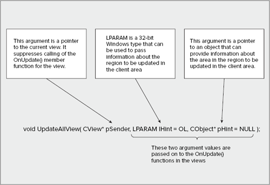
}When the m_pTempElement pointer is not nullptr, the specific action of the function has been extended to call the UpdateAllViews() member of your document class. This function communicates with the views by causing the OnUpdate() member function in each view to be called. The three arguments to UpdateAllViews() are described in Figure 17-2.
The first argument to the UpdateAllViews() function call is often the this pointer for the current view. This suppresses the call of the OnUpdate() function for the current view. This is a useful feature when the current view is already up to date. In the case of Sketcher, because you are rubber-banding, you want to get the current view redrawn as well, so by specifying the first argument as 0 you get the OnUpdate() function called for all the views, including the current view. This removes the need to call InvalidateRect() as you did before.
You don't use the second argument to UpdateAllViews() here, but you do pass the pointer to the new element through the third argument. By passing a pointer to the new element, you allow the views to figure out which bit of their client area needs to be redrawn.
To catch the information passed to the UpdateAllViews() function, you must add an override for the OnUpdate() member function to the view class. You can do this from the Class View through the Properties window for CSketcherView. As I'm sure you recall, you display the properties for a class by right-clicking the class name and selecting Properties from the pop-up. If you click the Overrides button in the Properties window, you'll be able to find OnUpdate in the list of functions you can override. Click the function name, then the <Add> OnUpdate option that shows in the drop-down list in the adjacent column. You'll be able to edit the code for the OnUpdate() override you have added in the Editor pane. You only need to add the highlighted code below to the function definition:
void CSketcherView::OnUpdate(CView* pSender, LPARAM lHint, CObject* pHint){// Invalidate the area corresponding to the element pointed to// if there is one, otherwise invalidate the whole client areaif(pHint){InvalidateRect(static_cast<CElement*>(pHint)->GetBoundRect());}else{InvalidateRect(nullptr);}}
Note that you must uncomment at least the name of the third parameter in the generated version of the function; otherwise, it won't compile with the additional code here. The three arguments passed to the OnUpdate() function in the view class correspond to the arguments that you passed in the UpdateAllViews() function call. Thus, pHint contains the address of the new element. However, you can't assume that this is always the case. The OnUpdate() function is also called when a view is first created, but with a null pointer for the third argument. Therefore, the function checks that the pHint pointer isn't nullptr and only then gets the bounding rectangle for the element passed as the third argument. It invalidates this area in the client area of the view by passing the rectangle to the InvalidateRect() function. This area is redrawn by the OnDraw() function in this view when the next WM_PAINT message is sent to the view. If the pHint pointer is nullptr, the whole client area is invalidated.
You might be tempted to consider redrawing the new element in the OnUpdate() function. This isn't a good idea. You should do permanent drawing only in response to the Windows WM_PAINT message. This means that the OnDraw() function in the view should be the only thing that's initiating any drawing operations for document data. This ensures that the view is drawn correctly whenever Windows deems it necessary.
If you build and execute Sketcher with the new modifications included, you should find that all the views are updated to reflect the contents of the document.
Adding scrolling to a view looks remarkably easy at first sight; the water is, in fact, deeper and murkier than it at first appears, but jump in anyway. The first step is to change the base class for CSketcherView from CView to CScrollView. This new base class has the scrolling functionality built in, so you can alter the definition of the CSketcherView class to this:
class CSketcherView: public CScrollView
{
   // Class definition as before...
};
You must also modify two lines of code at the beginning of the SketcherView.cpp file that refer to the base class for CSketcherView. You need to replace CView with CScrollView as the base class:
IMPLEMENT_DYNCREATE(CSketcherView, CScrollView)

BEGIN_MESSAGE_MAP(CSketcherView, CScrollView)
However, this is still not quite enough. The new version of the view class needs to know some things about the area you are drawing on, such as the size and how far the view is to be scrolled when you use the scroller. This information has to be supplied before the view is first drawn. You can put the code to do this in the OnInitialUpdate() function in the view class.
You supply the information required by calling a function that is inherited from the CScrollView class: SetScrollSizes(). The arguments to this function are explained in Figure 17-3.
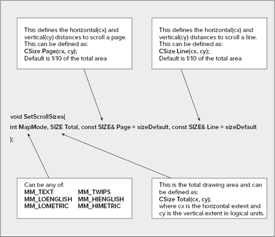
Scrolling a distance of one line occurs when you click on the up or down arrow on the scroll bar; a page scroll occurs when you click the scrollbar itself. You have an opportunity to change the mapping mode here. MM_LOENGLISH would be a good choice for the Sketcher application, but first get scrolling working with the MM_TEXT mapping mode because there are still some difficulties to be uncovered. (Mapping modes were introduced in Chapter 16.)
To add the code to call SetScrollSizes(), you need to override the default version of the OnInitialUpdate() function in the view. You access this in the same way as for the OnUpdate() function override — through the Properties window for the CSketcherView class. After you have added the override, just add the code to the function where indicated by the comment:
void CSketcherView::OnInitialUpdate()
{
   CScrollView::OnInitialUpdate();

   // Define document size
   CSize DocSize(20000,20000);

   // Set mapping mode and document size
   SetScrollSizes(MM_TEXT, DocSize, CSize(500,500), CSize(50,50));
}
This maintains the mapping mode as MM_TEXT and defines the total extent that you can draw on as 20,000 pixels in each direction. It also specifies a page scroll increment as 500 pixels in each direction and a line scroll increment as 50 pixels, because the defaults would be too large.
This is enough to get the scrolling mechanism working after a fashion. Build the program and execute it with these additions, and you'll be able to draw a few elements and then scroll the view. However, although the window scrolls OK, if you try to draw more elements with the view scrolled, things don't work as they should. The elements appear in a different position from where you draw them and they're not displayed properly. What's going on?
The problem is the coordinate systems you're using — and that plural is deliberate. You've actually been using two coordinate systems in all the examples up to now, although you may not have noticed. As you saw in the previous chapter, when you call a function such as LineTo(), it assumes that the arguments passed are logical coordinates. The function is a member of the CDC class that defines a device context, and the device context has its own system of logical coordinates. The mapping mode, which is a property of the device context, determines what the unit of measurement is for the coordinates when you draw something.
The coordinate data that you receive along with the mouse messages, on the other hand, has nothing to do with the device context or the CDC object — and outside of a device context, logical coordinates don't apply. The points passed to the OnLButtonDown() and OnMouseMove() handlers have coordinates that are always in device units — that is, pixels — and are measured relative to the upper left corner of the client area. These are referred to as client coordinates. Similarly, when you call InvalidateRect(), the rectangle is assumed to be defined in terms of client coordinates.
In MM_TEXT mode, the client coordinates and the logical coordinates in the device context are both in pixels, and so they're the same — as long as you don't scroll the window. In all the previous examples, there was no scrolling, so everything worked without any problems. With the latest version of Sketcher, it all works fine until you scroll the view, whereupon the logical coordinates origin (the 0,0 point) is moved by the scrolling mechanism, so it's no longer in the same place as the client coordinates origin. The units for logical coordinates and client coordinates are the same here, but the origins for the two coordinates systems are different. This situation is illustrated in Figure 17-4.
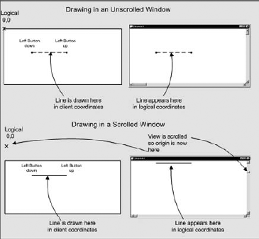
The left side shows the position in the client area where you draw, and the points that are the mouse positions defining the line. These are recorded in client coordinates. The right side shows where the line is actually drawn. Drawing is in logical coordinates, but you have been using client coordinate values. In the case of the scrolled window, the line appears displaced because the logical origin has been relocated.
This means that you are actually using the wrong values to define elements in the Sketcher program, and when you invalidate areas of the client area to get them redrawn, the rectangles passed to the function are also wrong — hence, the weird behavior of the program. With other mapping modes, it gets worse, because not only are the units of measurement in the two coordinate systems different, but the y axes also may be in opposite directions!
Consider what needs to be done to fix the problem. There are two things you may have to address:
You need to convert the client coordinates that you got with mouse messages to logical coordinates before you can use them to create elements.
You need to convert a bounding rectangle that you created in logical coordinates back to client coordinates if you want to use it in a call to
InvalidateRect().
These amount to making sure you always use logical coordinates when using device context functions, and always use client coordinates for other communications about the window. The functions you have to apply to do the conversions are associated with a device context, so you need to obtain a device context whenever you want to convert from logical to client coordinates or vice versa. You can use the coordinate conversion functions of the CDC class inherited by CClientDC to do the work.
The new version of the OnLButtonDown() handler incorporating this is as follows:
// Handler for left mouse button down message
void CSketcherView::OnLButtonDown(UINT nFlags, CPoint point)
{
CClientDC aDC(this); // Create a device contextOnPrepareDC(&aDC); // Get origin adjustedaDC.DPtoLP(&point); // Convert point to logical coordinatesm_FirstPoint = point; // Record the cursor position SetCapture(); // Capture subsequent mouse messages }
You obtain a device context for the current view by creating a CClientDC object and passing the pointer this to the constructor. The advantage of CClientDC is that it automatically releases the device context when the object goes out of scope. It's important that device contexts are not retained, as there are a limited number available from Windows and you could run out of them. If you use CClientDC, you're always safe.
As you're using CScrollView, the OnPrepareDC() member function inherited from that class must be called to set the origin for the logical coordinate system in the device context to correspond with the scrolled position. After you have set the origin by this call, you use the function DPtoLP(), which converts from Device Points to Logical Points, to convert the point value that's passed to the handler to logical coordinates. You then store the converted point, ready for creating an element in the OnMouseMove() handler.
The new code for the OnMouseMove() handler is as follows:
void CSketcherView::OnMouseMove(UINT nFlags, CPoint point)
{
   CClientDC aDC(this);             // Device context for the current view
   OnPrepareDC(&aDC);               // Get origin adjusted
   aDC.DPtoLP(&point);              // Convert point to logical coordinates
   if((nFlags&MK_LBUTTON)&&(this==GetCapture()))
   {
      m_SecondPoint = point;        // Save the current cursor position

   // Rest of the function as before...
}
The code for the conversion of the point value passed to the handler is essentially the same as in the previous handler, and that's all you need here for the moment. The last function that you must change is easy to overlook: the OnUpdate() function in the view class. This needs to be modified to the following:
void CSketcherView::OnUpdate(CView* pSender, LPARAM lHint, CObject* pHint)
{
   // Invalidate the area corresponding to the element pointed to
   // if there is one, otherwise invalidate the whole client area
   if(pHint)
   {
      CClientDC aDC(this);            // Create a device context
      OnPrepareDC(&aDC);              // Get origin adjusted

      // Get the enclosing rectangle and convert to client coordinates
      CRect aRect = static_cast<CElement*>(pHint)->GetBoundRect();
      aDC.LPtoDP(aRect);
      InvalidateRect(aRect);          // Get the area redrawn
   }
else
{
InvalidateRect(nullptr); // Invalidate the client area
}
}The modification here creates a CClientDC object and uses the LPtoDP() function member to convert the rectangle for the area that's to be redrawn to client coordinates.
If you now compile and execute Sketcher with the modifications I have discussed and are lucky enough not to have introduced any typos, it will work correctly, regardless of the scroller position.
Now, we will look into what you need to do to use the MM_LOENGLISH mapping mode. The advantage of using this mapping mode is that it provides drawings in logical units of 0.01 inches, which ensures that the drawing size is consistent on displays at different resolutions. This makes the application much more satisfactory from the user's point of view.
You can set the mapping mode in the call to SetScrollSizes() made from the OnInitialUpdate() function in the view class. You also need to specify the total drawing area: if you define it as 3,000 by 3,000, this provides a drawing area of 30 inches by 30 inches, which should be adequate. The default scroll distances for a line and a page are satisfactory, so you don't need to specify those. You can use the Class View to get to the OnInitialUpdate() function and then change it to the following:
void CSketcherView::OnInitialUpdate(void)
{
   CScrollView::OnInitialUpdate();

   // Define document size as 30×30ins in MM_LOENGLISH
   CSize DocSize(3000,3000);

   // Set mapping mode and document size.
   SetScrollSizes(MM_LOENGLISH, DocSize);
}
You just alter the arguments in the call to SetScrollSizes() for the mapping mode and the document size that you want. That's all that's necessary to enable the view to work in MM_LOENGLISH.
Note that you are not limited to setting the mapping mode once and for all. You can change the mapping mode in a device context at any time and draw different parts of the image to be displayed using different mapping modes. A function, SetMapMode(), is used to do this, but I won't be going into this any further here. You can get your application working just using MM_LOENGLISH. Whenever you create a CClientDC object for the view and call OnPrepareDC(), the device context that it owns has the mapping mode you've set in the OnInitialUpdate() function.
That should do it for the program as it stands. If you rebuild Sketcher, you should have scrolling working, with support for multiple views.
Being able to delete shapes is a fundamental requirement in a drawing program. One question relating to this is how you're going to select the element you want to delete. Of course, after you decide how you are going to select an element, your decision also applies to how you move an element, so you can treat moving and deleting elements as related problems. But first, consider how you're going to bring move and delete operations into the user interface for the program.
A neat way of providing move and delete functions would be to have a pop-up context menu appear at the cursor position when you click the right mouse button. You could then include Move and Delete as items on the menu. A pop-up that works like this is a very handy tool that you can use in lots of different situations.
How should the pop-up be used? The standard way that context menus work is that the user moves the mouse over a particular object and right-clicks it. This selects the object and pops up a menu containing a list of items relating to actions that can be performed on that object. This means that different objects can have different menus. You can see this in action in Developer Studio itself. When you right-click a class icon in Class View, you get a menu that's different from the one you get if you right-click the icon for a member function. The menu that appears is sensitive to the context of the cursor, hence the term "context menu." You have two contexts to consider in Sketcher. You could right-click with the cursor over an element, or you could right-click when there is no element under the cursor.
So how can you implement this functionality in the Sketcher application? You can do it simply by creating two menus: one for when you have an element under the cursor and one for when you don't. You can check if there's an element under the cursor when the user clicks the right mouse button. If there is an element under the cursor, you can highlight the element so that the user knows exactly which element the context pop-up is referring to.
First, take a look at how you can create a pop-up at the cursor, and, after that works, you can come back to how to implement the details of the move and delete operations.
You will need two context menu pop-ups: one for when there is an element under the mouse cursor, and another for when there isn't.
The first step is to create a menu containing Move and Delete as menu items that will apply to the element under the cursor. The other pop-up will contain a combination of menu items from the Element and Color menus. So change to Resource View and expand the list of resources. Right-click the Menu folder to bring up a context menu — another demonstration of what you are now trying to create in the Sketcher application. Select Insert Menu to create a new menu. This has a default ID IDR_MENU1 assigned, but you can change this. Select the name of the new menu in the Resource View and display the Properties window for the resource by pressing Alt+Enter (this is a shortcut to the View
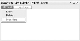
You can now create a new item on the menu bar in the Editor pane. This can have any old caption because it won't actually be seen by the user; the caption element will be OK. Now you can add the Move and Delete items to the element pop-up. The default IDs of ID_ELEMENT_MOVE and ID_ELEMENT_DELETE will do fine, but you can change them if you want in the Properties window for each item. Figure 17-5 shows how the new element menu looks.
Save the menu and create another with the ID IDR_NOELEMENT_MENU; you can make the caption no element this time. The second menu will contain the list of available element types and colors, identical to the items on the Element and Color menus on the main menu bar, but here separated by a separator. The IDs you use for these items must be the same as the ones you applied to the IDR_SketcherTYPE menu. This is because the handler for a menu is associated with the menu ID. Menu items with the same ID use the same handlers, so the same handler is used for the Line menu item regardless of whether it's invoked from the main menu pop-up or from the context menu.
You have a shortcut that saves you from having to create all these menu items one by one. If you display the IDR_SketcherTYPE menu and extend the Element menu, you can select all the menu items by clicking the first item and then clicking the last item while holding down the Shift key. You can then right-click the selection and select Copy from the pop-up or simply press Ctrl+C. If you then return to the IDR_NOELEMENT_MENU and right-click the first item on the no element menu, you can insert the complete contents of the Element menu by selecting Paste from the pop-up or by pressing Ctrl+V. The copied menu items will have the same IDs as the originals. To insert the separator, just right-click the empty menu item and select Insert Separator from the pop-up. Repeat the process for the Color menu items and you're done.
Close the properties box and save the resource file. At the moment, all you have is the definition of the context menus in a resource file. It isn't connected to the code in the Sketcher program. You now need to associate these menus and their IDs with the view class. You also must create command handlers for the menu items in the pop-up corresponding to the IDs ID_ELEMENT_MOVE and ID_ELEMENT_DELETE.
Context menus are managed in an MFC program by an object of type CContextManager. The CSketcherApp class object already has a member of type CContextManager defined, and you can use this object to manage your context menus. Go to the CSketcherApp class in the Class View and go to the definition of the PreLoadState() member function. Add the following lines of code:
void CSketcherApp::PreLoadState()
{
/*
  BOOL bNameValid;
  CString strName;
  bNameValid = strName.LoadString(IDS_EDIT_MENU);
  ASSERT(bNameValid);
GetContextMenuManager()->AddMenu(strName, IDR_POPUP_EDIT);*/GetContextMenuManager()->AddMenu(_T("Element menu"), IDR_ELEMENT_MENU);GetContextMenuManager()->AddMenu(_T("No element menu"), IDR_NOELEMENT_MENU);}
Note
I have commented out the original lines of code that were there, to show that they are no longer required. You should remove these lines because they display the Edit menu as a context menu, and you don't want that to happen.
Calling the GetContextManager() function for the application object returns a pointer to the CContextManager object. The AddMenu() function adds the menu specified by the second argument to the CContextManager object. The first argument specifies a name for the new menu. You can specify the name explicitly, as in the code here, or you can specify a resource ID for the string that is the name.
Note how the text strings in the first argument to the AddMenu() function are enclosed within the _T() macro. This is because we are using the Unicode version of the MFC libraries. The _T() macro selects the correct type for the string, depending on whether or not the _UNICODE symbol is defined for the project. You may remember we left the Use Unicode libraries option checked when we first created the Sketcher project. You should always use the _T() macro when defining string literals in a Unicode program. When you are using the MFC Unicode libraries, you should also use the TCHAR type instead of the char type in your code, LPTSTR instead of char*, and LPCTSTR instead of const char*.
A context menu can be displayed in response to a WM_CONTEXTMENU message, but the default code generated by the wizard calls the OnContextMenu() handler from the OnRButtonUp() handler. If you look at the CSketcherView class implementation, there should already be a definition of the OnRButtonUp() handler and the OnContextMenu() handler, and this is where you'll put the code to display the new context menus you have just defined. Note that the default code for the OnRButtonUp() handler calls ClientToScreen() to convert the coordinates of the current cursor position to screen coordinates.
You can then add the following code to the OnContextMenu() handler:
void CSketcherView::OnContextMenu(CWnd* pWnd, CPoint point)
{
#ifndef SHARED_HANDLERS

// theApp.GetContextMenuManager()->ShowPopupMenu(IDR_POPUP_EDIT,
//                                           point.x, point.y, this, TRUE);
  if(m_pSelected)
    theApp.GetContextMenuManager()->ShowPopupMenu(IDR_ELEMENT_MENU,
                                             point.x, point.y, this);
  else
    theApp.GetContextMenuManager()->ShowPopupMenu(IDR_NOELEMENT_MENU,
                                             point.x, point.y, this);
#endif
}
The first line of code was already present, and I have commented it out to indicate that it is not required for Sketcher. You should remove this line because it displays the Edit menu as a context menu, and you don't want that to happen.
The new code chooses between the two context menus you have created based on whether or not the m_pSelected member is null. m_pSelected will store the address of the element under the mouse cursor, or nullptr if there isn't one. You will add this member to the view class in a moment. Calling the ShowPopupMenu() function for the CContextMenuManager object displays the pop-up identified by the first argument at the position in the client area specified by the second and third arguments.
Add m_pSelected as a protected member of the CSketcherView class as type CElement*. You can initialize this member to nullptr in the view class constructor.
Now, you can add the handlers for the items in the element pop-up menu. Return to the Resource View and double-click IDR_ELEMENT_MENU. Right-click the Move menu item and then select Add Event Handler from the pop-up. You can then specify the handler in the dialog for the Event Handler wizard. It's a COMMAND handler and you create it in the CSketcherView class. Click the Add and Edit button to create the handler function. You can follow the same procedure to create the hander for the Delete menu item.
You don't have to do anything for the no element context menu, as you already have handlers written for it in the document class. These automatically take care of the messages from the pop-up items.
We will create a very simple mechanism for selecting an element. An element in a sketch will be selected whenever the mouse cursor is within the bounding rectangle for an element. For this to be effective, Sketcher must track at all times, whether or not there is an element under the cursor.
To keep track of which element is under the cursor, you can add code to the OnMouseMove() handler in the CSketcherView class. This handler is called every time the mouse cursor moves, so all you have to do is add code to determine whether there's an element under the current cursor position and set m_pSelected accordingly. The test for whether a particular element is under the cursor is simple: if the cursor position is within the bounding rectangle for an element, that element is under the cursor. Here's how you can modify the OnMouseMove() handler to determine whether there's an element under the cursor:
void CSketcherView::OnMouseMove(UINT nFlags, CPoint point)
{
  // Define a Device Context object for the view
  CClientDC aDC(this);              // DC is for this view
  OnPrepareDC(&aDC);                // Get origin adjusted
  aDC.DPtoLP(&point);               // Convert point to logical coordinates
  if((nFlags & MK_LBUTTON) && (this == GetCapture()))
  {
    // Code as before...
}else{ // We are not creating an element, so select an elementCSketcherDoc* pDoc=GetDocument(); // Get a pointer to the documentm_pSelected = pDoc->FindElement(point); // Set selected element}}
The new code is very simple and is executed only when we are not creating a new element. The else clause in the if statement calls the FindElement() function for the document object that you'll add shortly and stores the element address that is returned in m_pSelected. The FindElement() function has to search the document for the first element that has a bounding rectangle that encloses point. You can add FindElement() to the document class as a public member and implement it like this:
// Finds the element under the point
CElement* CSketcherDoc::FindElement(const CPoint& point)const
{
  for(auto rIter = m_ElementList.rbegin() ; rIter != m_ElementList.rend() ; ++rIter)
  {
    if((*rIter)->GetBoundRect().PtInRect(point))
      return *rIter;
  }
  return nullptr;
}
You use a reverse-iterator to search the list from the end, which means the most recently created and, therefore, last-drawn element will be found first. The PtInRect() member of the CRect class returns TRUE if the point you pass as the argument lies within the rectangle, and FALSE otherwise. Here, you use this function to test whether or not the point lies within any bounding rectangle for an element in the sketch. The address of the first element for which this is true is returned. If no element in the sketch is found, the loop will end and nullptr will be returned. The code is now in a state where you can test the context menus.
You have added all the code you need to make the pop-ups operate, so you can build and execute Sketcher to try it out. When you right-click the mouse, or press Shift+F10, a context menu will be displayed. If there are no elements under the cursor, the second context pop-up appears, enabling you to change the element type and color. These options work because they generate exactly the same messages as the main menu options, and because you have already written handlers for them.
If there is an element under the cursor, the first context menu will appear with Move and Delete on it. It won't do anything at the moment, as you've yet to implement the handlers for the messages it generates. Try right-button clicks outside the view window. Messages for these are not passed to the document view window in your application, so the pop-up is not displayed.
Ideally, the user will want to know which element is under the cursor before right-clicking to get the context menu. When you want to delete an element, you want to know which element you are operating on. Equally, when you want to use the other context menu — to change color, for example — you need to be sure no element is under the cursor when you right-click the mouse. To show precisely which element is under the cursor, you need to highlight it in some way before a right-button click occurs.
You can change the Draw() member function for an element to accommodate this. All you need to do is pass an extra argument to the Draw() function to indicate when the element should be highlighted. If you pass the address of the currently-selected element that you save in the m_pSelected member of the view to the Draw() function, you will be able to compare it to the this pointer to see if it is the current element.
All highlights will work in the same way, so let's take the CLine member as an example. You can add similar code to each of the classes for the other element types. Before you start changing CLine, you must first amend the definition of the base class CElement:
class CElement : public CObject
{
   protected:
     int m_PenWidth;                  // Pen width
     COLORREF m_Color;                // Color of an element
     CRect m_EnclosingRect;           // Rectangle enclosing an element
   public:
     virtual ~CElement();
     // Virtual draw operation
     virtual void Draw(CDC* pDC, CElement* pElement=nullptr) {}

     CRect GetBoundRect() const;     // Get the bounding rectangle for an element

   protected:
     CElement();                     // Here to prevent it being called
}; 
The change is to add a second parameter to the virtual Draw() function. This is a pointer to an element. The reason for initializing the second parameter to nullptr is that this allows the use of the function with just one argument; the second will be supplied as nullptr by default.
You need to modify the declaration of the Draw() function in each of the classes derived from CElement in exactly the same way. For example, you should change the CLine class definition to the following:
class CLine :
  public CElement
{
   public:
      CLine(void);
      // Function to display a line
      virtual void Draw(CDC* pDC, CElement* pElement=nullptr);

      // Constructor for a line object
      CLine(const CPoint& Start, const CPoint& End, COLORREF aColor);
protected:
CPoint m_StartPoint; // Start point of line
CPoint m_EndPoint; // End point of line
CLine(void); // Default constructor - should not be used
};The implementation for each of the Draw() functions for the classes derived from CElement needs to be extended in the same way. The function for the CLine class is as follows:
void CLine::Draw(CDC* pDC, CElement* pElement){ // Create a pen for this object and // initialize it to the object color and line width m_PenWidth CPen aPen;if(!aPen.CreatePen(PS_SOLID, m_PenWidth,this==pElement ? SELECT_COLOR : m_Color)){ // Pen creation failed. Abort the program AfxMessageBox(_T("Pen creation failed drawing a line"), MB_OK); AfxAbort(); } CPen* pOldPen = pDC->SelectObject(&aPen); // Select the pen // Now draw the line pDC->MoveTo(m_StartPoint); pDC->LineTo(m_EndPoint); pDC->SelectObject(pOldPen); // Restore the old pen }
This is a very simple change. The third argument to the CreatePen() function is now a conditional expression. You choose the color for the pen based on whether or not pElement is the same as the current CLine element pointer, this. If it is, you choose SELECT_COLOR for the pen rather than the original color for the line.
When you have updated the Draw() functions for all the subclasses of CElement, you can add the definition for SELECT_COLOR to the SketcherConstants.h file:
// SketcherConstants.h : Definitions of constants
//Definitions of constants

#pragma once

// Element type definitions
enum ElementType{LINE, RECTANGLE, CIRCLE, CURVE};

// Color values for drawing
const COLORREF BLACK = RGB(0,0,0);
const COLORREF RED = RGB(255,0,0);
const COLORREF GREEN = RGB(0,255,0);
const COLORREF BLUE = RGB(0,0,255);
const COLORREF SELECT_COLOR = RGB(255,0,180);///////////////////////////////////
You have nearly implemented the highlighting. The derived classes of the CElement class are now able to draw themselves as selected when required — you just need a mechanism to cause an element to be selected. So where should you create this? You can determine which element, if any, is under the cursor in the OnMouseMove() handler in the CSketcherView class, so that's obviously the place to expedite the highlighting.
The amendments to the OnMouseMove() handler are as follows:
void CSketcherView::OnMouseMove(UINT nFlags, CPoint point)
{
  // Define a Device Context object for the view
  CClientDC aDC(this);                      // DC is for this view
  OnPrepareDC(&aDC);                        // Get origin adjusted
  aDC.DPtoLP(&point);                       // Convert point to logical coordinates
  if((nFlags & MK_LBUTTON) && (this == GetCapture()))
  {
    // Code as before...
  }
  else
   {  // We are not creating an element to do highlighting
    CSketcherDoc* pDoc=GetDocument();         // Get a pointer to the document
    CElement* pOldSelected(m_pSelected);
    m_pSelected = pDoc->FindElement(point);   // Set selected element
    if(m_pSelected != pOldSelected)
    {
      if(m_pSelected)
        InvalidateRect(m_pSelected->GetBoundRect(), FALSE);
      if(pOldSelected)
        InvalidateRect(pOldSelected->GetBoundRect(), FALSE);
      pDoc->UpdateAllViews(nullptr);
    }
  }
}
You must keep track of any previously highlighted element because, if there's a new one, you must un-highlight the old one. To do this, you save the value of m_pSelected in pOldSelected before you check for a selected element. You then store the address returned by the FindElement() function for the document object in m_pSelected.
If pOldSelected and m_pSelected are equal, then either they both contain the address of the same element or they are both zero. If they both contain a valid address, the element will already have been highlighted last time around. If they are both zero, nothing is highlighted and nothing needs to be done. Thus, in either case, you do nothing.
Thus, you want to do something only when m_pSelected is not equal to pOldSelected. If m_pSelected is not nullptr, you need to get it redrawn, so you call InvalidateRect() with the first argument as the bounding rectangle for the element, and the second argument as FALSE so as not to erase the background. If pOldSelected is also not null, you must un-highlight the old element by invalidating its bounding rectangle in the same way. Finally, you call UpdateAllViews() for the document object to get the views updated.
You still need to arrange that the highlighted element is actually drawn highlighted. Somewhere, the m_pSelected pointer must be passed to the draw function for each element. The only place to do this is in the OnDraw() function in the view:
void CSketcherView::OnDraw(CDC* pDC)
{
  CSketcherDoc* pDoc = GetDocument();
  ASSERT_VALID(pDoc);
  if (!pDoc)
    return;

  CElement* pElement(nullptr);
  for(auto iter = pDoc->begin() ; iter != pDoc->end() ; ++iter)
  {
    pElement = *iter;
    if(pDC->RectVisible(pElement->GetBoundRect())) // If the element is visible
         pElement->Draw(pDC, m_pSelected);         // ...draw it
  }
}
You need to change only one line. The Draw() function for an element has the second argument added to communicate the address of the element to be highlighted.
This is all that's required for the highlighting to work all the time. It wasn't trivial but, on the other hand, it wasn't terribly difficult. You can build and execute Sketcher to try it out. Any time there is an element under the cursor, the element is drawn in magenta. This makes it obvious which element the context menu is going to act on before you right-click the mouse, and means that you know in advance which context menu will be displayed.
The next step is to provide code in the bodies of the handlers for the Move and Delete menu items that you added earlier. You can add the code for Delete first, as that's the simpler of the two.
The code that you need in the OnElementDelete() handler in the CSketcherView class to delete the currently selected element is simple:
void CSketcherView::OnElementDelete()
{
  if(m_pSelected)
  {
    CSketcherDoc* pDoc = GetDocument();// Get the document pointer
    pDoc->DeleteElement(m_pSelected);  // Delete the element
    pDoc->UpdateAllViews(nullptr);     // Redraw all the views
    m_pSelected = nullptr;             // Reset selected element ptr
  }
}
The code to delete an element is executed only if m_pSelected contains a valid address, indicating that there is an element to be deleted. You get a pointer to the document and call the function DeleteElement() for the document object; you'll add this member to the CSketcherDoc class in a moment. When the element has been removed from the document, you call UpdateAllViews() to get all the views redrawn without the deleted element. Finally, you set m_pSelected to nullptr to indicate that there isn't an element selected.
You can add a declaration for DeleteElement() as a public member of the CSketcherDoc class:
class CSketcherDoc : public CDocument
{
protected: // create from serialization only
       CSketcherDoc();
       DECLARE_DYNCREATE(CSketcherDoc)

// Attributes
public:

// Operations
public:
      unsigned int GetElementType() const      // Get the element type
         { return m_Element; }
      COLORREF GetElementColor() const         // Get the element color
         { return m_Color; }
   void AddElement(CElement* pElement)         // Add an element to the list
      { m_ElementList.push_back(pElement); }
   std::list<CElement*>::const_iterator begin() const
     { return m_ElementList.begin(); }
   std::list<CElement*>::const_iterator end() const
     { return m_ElementList.end(); }
  CElement* FindElement(const CPoint& point) const;

   void DeleteElement(CElement* pElement);     // Delete an element

// Rest of the class as before...
};
It accepts as an argument a pointer to the element to be deleted and returns nothing. You can implement it in SketcherDoc.cpp as the following:
// Delete an element from the sketch
void CSketcherDoc::DeleteElement(CElement* pElement)
{
  if(pElement)
  {
    m_ElementList.remove(pElement);    // Remove the pointer from the list
    delete pElement;                   // Delete the element from the heap
  }
}
You shouldn't have any trouble understanding how this works. You use pElement with the remove() member of the list<CElement*> object to delete the pointer from the list, then you delete the element pointed to by the parameter pElement from the heap.
That's all you need in order to delete elements. You should now have a Sketcher program in which you can draw in multiple scrolled views, and delete any of the elements in your sketch from any of the views.
Moving the selected element is a bit more involved. As the element must move along with the mouse cursor, you must add code to the OnMouseMove() method to provide for this behavior. As this function is also used to draw elements, you need a mechanism for indicating when you're in "move" mode. The easiest way to do this is to have a flag in the view class, which you can call m_MoveMode. If you make it of type BOOL, the Windows API Boolean type, you use the value TRUE for when move mode is on, and FALSE for when it's off. Of course, you can also define it as the C++ fundamental type, bool, with the values true and false.
You'll also have to keep track of the cursor during the move, so you can add another data member in the view for this. You can call it m_CursorPos, and it will be of type CPoint. Another thing you should provide for is the possibility of aborting a move. To do this, you must remember the first position of the cursor when the move operation started, so you can move the element back when necessary. This is another member of type CPoint, and it is called m_FirstPos. Add the three new members to the protected section of the view class:
class CSketcherView: public CScrollView
{
  // Rest of the class as before...

  protected:
    CPoint m_FirstPoint;       // First point recorded for an element
    CPoint m_SecondPoint;      // Second point recorded for an element
    CElement* m_pTempElement;  // Pointer to temporary element
    CElement* m_pSelected;     // Currently selected element
    bool m_MoveMode;           // Move element flag
    CPoint m_CursorPos;        // Cursor position
    CPoint m_FirstPos;         // Original position in a move

   // Rest of the class as before...
};
These must also be initialized in the constructor for CSketcherView, so modify it to the following:
CSketcherView::CSketcherView() : m_FirstPoint(CPoint(0,0)) , m_SecondPoint(CPoint(0,0)) , m_pTempElement(nullptr) , m_pSelected(nullptr), m_MoveMode(false), m_CursorPos(CPoint(0,0)), m_FirstPos(CPoint(0,0)){ // TODO: add construction code here }
The element move process starts when the Move menu item from the context menu is selected. Now, you can add the code to the message handler for the Move menu item to set up the conditions necessary for the operation:
void CSketcherView::OnElementMove()
{
   CClientDC aDC(this);
   OnPrepareDC(&aDC);              // Set up the device context
   GetCursorPos(&m_CursorPos);     // Get cursor position in screen coords
   ScreenToClient(&m_CursorPos);   // Convert to client coords
   aDC.DPtoLP(&m_CursorPos);       // Convert to logical
   m_FirstPos = m_CursorPos;       // Remember first position
   m_MoveMode = true;              // Start move mode
}
You are doing four things in this handler:
Getting the coordinates of the current position of the cursor, because the move operation starts from this reference point.
Converting the cursor position to logical coordinates, because your elements are defined in logical coordinates.
Remembering the initial cursor position in case the user wants to abort the move later.
Setting the move mode on as a flag for the
OnMouseMove()handler to recognize.
The GetCursorPos() function is a Windows API function that stores the current cursor position in m_CursorPos. Note that you pass a reference to this function. The cursor position is in screen coordinates (that is, coordinates measured in pixels relative to the upper-left corner of the screen). All operations with the cursor are in screen coordinates. You want the position in logical coordinates, so you must do the conversion in two steps. The ScreenToClient() function (which is an inherited member of the view class) converts from screen to client coordinates, and then you apply the DPtoLP() function member of the aDC object to the result to convert to logical coordinates.
After saving the initial cursor position in m_FirstPos, you set m_MoveMode to true so that the OnMouseMove() handler can deal with moving the element.
Now that you have set the move mode flag, it's time to update the mouse move message handler to deal with moving an element.
Moving an element only occurs when move mode is on and the cursor is being moved. Therefore, all you need to do in OnMouseMove() is add code to handle moving an element in a block that gets executed only when m_MoveMode is TRUE. The new code to do this is as follows:
void CSketcherView::OnMouseMove(UINT nFlags, CPoint point)
{
  CClientDC aDC(this);              // DC is for this view
  OnPrepareDC(&aDC);                // Get origin adjusted

  aDC.DPtoLP(&point);               // Convert point to logical coordinates
// If we are in move mode, move the selected element and returnif(m_MoveMode){MoveElement(aDC, point); // Move the elementreturn;}// Rest of the mouse move handler as before... }
This addition doesn't need much explaining, really, does it? The if statement verifies that you're in move mode and then calls a function MoveElement(), which does what is necessary for the move. All you have to do now is implement this function.
Add the declaration for MoveElement() as a protected member of the CSketcherView class by adding the following at the appropriate point in the class definition:
void MoveElement(CClientDC& aDC, const CPoint& point); // Move an element
As always, you can also right-click the class name in Class View to do this, if you want to. The function needs access to the object encapsulating a device context for the view, aDC, and the current cursor position, point, so both of these are reference parameters. The implementation of the function in the SketcherView.cpp file is as follows:
void CSketcherView::MoveElement(CClientDC& aDC, const CPoint& point)
{
  CSize distance = point - m_CursorPos;   // Get move distance
  m_CursorPos = point;                    // Set current point as 1st for
                                          // next time

  // If there is an element selected, move it
  if(m_pSelected)
  {
    aDC.SetROP2(R2_NOTXORPEN);
    m_pSelected->Draw(&aDC, m_pSelected); // Draw the element to erase it
    m_pSelected->Move(distance);          // Now move the element
    m_pSelected->Draw(&aDC, m_pSelected); // Draw the moved element
  }
}
The distance to move the element that is currently selected is stored locally as a CSize object, distance. The CSize class is specifically designed to represent a relative coordinate position and has two public data members, cx and cy, which correspond to the x and y increments. These are calculated as the difference between the current cursor position, stored in point, and the previous cursor position, saved in m_CursorPos. This uses the subtraction operator, which is overloaded in the CPoint class. The version you are using here returns a CSize object, but there is also a version that returns a CPoint object. You can usually operate on CSize and CPoint objects combined. You save the current cursor position in m_CursorPos for use the next time this function is called, which occurs if there is a further mouse move message during the current move operation.
You implement moving an element in the view using the R2_NOTXORPEN drawing mode, because it's easy and fast. This is exactly the same as what you have been using during the creation of an element. You redraw the selected element in its current color (the selected color) to reset it to the background color, and then call the function Move() to relocate the element by the distance specified by distance. You'll add this function to the element classes in a moment. When the element has moved itself, you simply use the Draw() function once more to display it highlighted at the new position. The color of the element will revert to normal when the move operation ends, as the OnLButtonUp() handler will redraw all the windows normally by calling UpdateAllViews().
Add the Move() function as a virtual member of the base class, CElement. Modify the class definition to the following:
class CElement : public CObject
{
   protected:
     int m_PenWidth;                   // Pen width
     COLORREF m_Color;                 // Color of an element
     CRect m_EnclosingRect;            // Rectangle enclosing an element
   public:
     virtual ~CElement();

     // Virtual draw operation
     virtual void Draw(CDC* pDC, CElement* pElement=nullptr) {}
     virtual void Move(const CSize& aSize){} // Move an element

     CRect GetBoundRect();             // Get the bounding rectangle for an element

   protected:
     CElement();                       // Here to prevent it being called
};
As discussed earlier in relation to the Draw() member, although an implementation of the Move() function here has no meaning, you can't make it a pure virtual function because of the requirements of serialization.
You can now add a declaration for the Move() function as a public member of each of the classes derived from CElement. It is the same in each:
virtual void Move(const CSize& aSize); // Function to move an element
Next, you can add the implementation of the Move() function in the CLine class to Elements.cpp:
void CLine::Move(const CSize& aSize)
{
  m_StartPoint += aSize;               // Move the start point
  m_EndPoint += aSize;                 // and the end point
  m_EnclosingRect += aSize;            // Move the enclosing rectangle
}
This is easy because of the overloaded += operators in the CPoint and CRect classes. They all work with CSize objects, so you just add the relative distance specified by aSize to the start and end points for the line and to the enclosing rectangle.
Moving a CRectangle object is even easier:
void CRectangle::Move(const CSize& aSize)
{
  m_EnclosingRect+= aSize;             // Move the rectangle
}
Because the rectangle is defined by the m_EnclosingRect member, that's all you need to move it.
The Move() member of the CCircle class is identical:
void CCircle::Move(const CSize& aSize)
{
  m_EnclosingRect+= aSize;             // Move rectangle defining the circle
}
Moving a CCurve object is a little more complicated, because it's defined by an arbitrary number of points. You can implement the function as follows:
void CCurve::Move(const CSize& aSize)
{
  m_EnclosingRect += aSize;            // Move the rectangle
  // Now move all the points
  std::for_each(m_Points.begin(), m_Points.end(),
                                 [&aSize](CPoint& p){ p += aSize; });
}
So that you don't forget about them, I have used an algorithm and a lambda expression here. You will need to add an #include directive for the algorithm header to Elements.cpp.
There's still not a lot to it. You first move the enclosing rectangle stored in m_EnclosingRect, using the overloaded += operator for CRect objects. You then use the STL for_each algorithm to apply the lambda expression that is the third argument to all the points defining the curve. The capture clause for the lambda expression accesses the aSize parameter by reference. Of course, the lambda parameter must be a reference so the original points can be updated.
Once you have clicked on the Move menu item, the element under the cursor will move around as you move the mouse. All that remains now is to add the capability to drop the element in position once the user has finished moving it, or to abort the whole move. To drop the element in its new position, the user clicks the left mouse button, so you can manage this operation in the OnLButtonDown() handler. To abort the operation, the user clicks the right mouse button — so you can add the code to the OnRButtonDown() handler to deal with this.
You can take care of the left mouse button first. You'll have to provide for this as a special action when move mode is on. The changes are highlighted in the following:
void CSketcherView::OnLButtonDown(UINT nFlags, CPoint point)
{
  CClientDC aDC(this);                 // Create a device context
  OnPrepareDC(&aDC);                   // Get origin adjusted
aDC.DPtoLP(&point); // convert point to Logicalif(m_MoveMode){// In moving mode, so drop the elementm_MoveMode = false; // Kill move modem_pSelected = nullptr; // De-select the elementGetDocument()->UpdateAllViews(0); // Redraw all the viewsreturn;}m_FirstPoint = point; // Record the cursor position SetCapture(); // Capture subsequent mouse messages }
The code is pretty simple. You first make sure that you're in move mode. If this is the case, you just set the move mode flag back to false and then de-select the element. This is all that's required because you've been tracking the element with the mouse, so it's already in the right place. Finally, to tidy up all the views of the document, you call the document's UpdateAllViews() function, causing all the views to be redrawn.
Add a handler for the WM_RBUTTONDOWN message to CSketcherView using the Properties window for the class. The implementation for aborting a move must do two things. It must move the element back to where it was and turn off move mode. You can move the element back in the right-button-down handler, but you must leave switching off move mode to the right-button-up handler to allow the context menu to be suppressed. The code to move the element back is as follows:
void CSketcherView::OnRButtonDown(UINT nFlags, CPoint point)
{
   if(m_MoveMode)
   {
     // In moving mode, so drop element back in original position
     CClientDC aDC(this);
     OnPrepareDC(&aDC);                      // Get origin adjusted
     MoveElement(aDC, m_FirstPos);           // Move element to original position
     m_pSelected = nullptr;                  // De-select element
     GetDocument()->UpdateAllViews(nullptr); // Redraw all the views
  }
}
You first create a CClientDC object for use in the MoveElement() function. You then call the MoveElement() function to move the currently selected element the distance from the current cursor position to the original cursor position that we saved in m_FirstPos. After the element has been repositioned, you just deselect the element and get all the views redrawn.
The last thing you must do is switch off move mode in the button-up handler:
void CSketcherView::OnRButtonUp(UINT /* nFlags */, CPoint point)
{
  if(m_MoveMode)
  {
    m_MoveMode = false;
    return;
  }
ClientToScreen(&point); OnContextMenu(this, point); }
Now, the context menu gets displayed only when move mode is not in progress.
There's still a limitation that you might want to get over. If the element you want to move or delete is enclosed by the rectangle of another element that is drawn after the element you want, you won't be able to highlight it because Sketcher always finds the outer element first. The outer element completely masks the element it encloses. This is a result of the sequence of elements in the list. You could fix this by adding a Send to Back item to the context menu that would move an element to the beginning of the list.
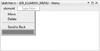
Add a separator and a menu item to the element drop-down in the IDR_ELEMENT_MENU resource, as shown in Figure 17-6.
You can add a handler for the item to the view class through the Properties window for the CSketcherView class. It's best to handle it in the view because that's where you record the selected element. Select the Events toolbar button in the Properties window for the class and double-click the message ID ID_ELEMENT_SENDTOBACK. You'll then be able to select COMMAND below and <Add>OnElementSendtoback in the right column. You can implement the handler as follows:
void CSketcherView:: OnElementSendtoback()
{
  GetDocument()->SendToBack(m_pSelected);  // Move element to start of list
}
You'll get the document to do the work by passing the currently selected element pointer to a public function, SendToBack(), that you implement in the CSketcherDoc class. Add it to the class definition with a void return type and a parameter of type CElement*. You can implement this function as follows:
void CSketcherDoc::SendToBack(CElement* pElement)
{
  if(pElement)
  {
m_ElementList.remove(pElement); // Remove the element from the list
m_ElementList.push_front(pElement); // Put it back at the beginning of the list
}
}After checking that the parameter is not null, you remove the element from the list by calling remove(). Of course, this does not delete the element from memory; it just removes the element pointer from the list. You then add the element pointer back at the beginning of the list, using the push_front() function.
With the element moved to the beginning of the list, it cannot mask any of the others because you search for an element to highlight from the end. You will always find one of the other elements first if the applicable bounding rectangle encloses the current cursor position. The Send to Back menu option is always able to resolve any element masking problem in the view.
It's time to extend CLR Sketcher by adding a class encapsulating a complete sketch. You'll also implement element highlighting and a context menu with the ability to move and delete elements. You can adopt a different approach to drawing elements in this version of Sketcher that will make the move element operation easy to implement. Before you start extending CLR Sketcher and working with the element classes, let's explore another feature of the Graphics class that will be useful in the application.
The Graphics class contains functions that can move, rotate, and scale the entire drawing coordinate system. This is a very powerful capability that you can use in the element drawing operations in Sketcher. The following table describes the most useful functions that transform the coordinate system.
TRANSFORM FUNCTION | DESCRIPTION |
|---|---|
TranslateTransform( float dx, float dy) | Translates the coordinate system origin by |
RotateTransform( float angle) | Rotates the coordinate system about the origin by |
ScaleTransform( float scaleX, float scaleY) | Scales the x-axis by multiplying by |
ResetTransform() | Resets the current transform state for a |
You will be using the TranslateTransform() function in the element drawing operations. To draw an element, you can translate the origin for the coordinate system to the position specified by the inherited position member of the Element class, draw the element relative to the origin (0,0) and then restore the coordinate system to its original state. This process is illustrated in Figure 17-7, which shows how you draw a circle.
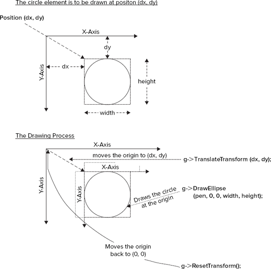
You can change the Draw() function in the Circle class to use the TranslateTransform() function:
virtual void Draw(Graphics^ g) override
    {
      g->TranslateTransform(safe_cast<float>(position.X),
                            safe_cast<float>(position.Y));
g->DrawEllipse(pen, 0, 0, width,height);g->ResetTransform();}
The TranslateTransform() function requires arguments of type float, so you cast the coordinates to this type. This is not absolutely necessary, but you will get warning messages from the compiler if you don't, so it is a good idea to always put the casts in.
To make the most efficient use of the TranslateTransform() function when drawing a line, you could change the Line class constructor to store the end point relative to position:
Line(Color color, Point start, Point end)
{
  pen = gcnew Pen(color);
  this->color = color;
  position = start;
  this->end = end - Size(start);
  boundRect = System::Drawing::Rectangle(Math::Min(position.X, end.X),
                                         Math::Min(position.Y, end.Y),
                Math::Abs(position.X - end.X), Math::Abs(position.Y - end.Y));

  // Provide for lines that are horizontal or vertical
  if(boundRect.Width < 2) boundRect.Width = 2;
  if(boundRect.Height < 2) boundRect.Height = 2;
}
The subtraction operator for the Point class enables you to subtract a Size object from a Point object. Here, you construct the Size object from the start object that is passed to the constructor. This results in the end member coordinates being relative to start.
Change the Draw() function in the Line class to the following:
virtual void Draw(Graphics^ g) override
{
  g->TranslateTransform(safe_cast<float>(position.X),
                           safe_cast<float>(position.Y));
  g->DrawLine(pen, 0, 0, end.X, end.Y);
  g->ResetTransform();
}
The DrawLine() function now draws the line relative to 0,0 after the TranslateTransform() function moves the origin of the client area to position, the start point for the line.
The Draw() function for the Rectangle class is very similar to that for the Circle class:
virtual void Draw(Graphics^ g) override
{
  g->TranslateTransform(safe_cast<float>(position.X),
                        safe_cast<float>(position.Y));
  g->DrawRectangle(pen, 0, 0, width, height);
  g->ResetTransform();
}
The Draw() function for the Curve class is simpler than before:
virtual void Draw(Graphics^ g) override
    {
      g->TranslateTransform(safe_cast<float>(position.X),
                            safe_cast<float>(position.Y));
      Point previous(0,0);
      for each(Point p in points)
      {
        g->DrawLine(pen, previous, p);
        previous = p;
      }
      g->ResetTransform();
 }
The points in the points vector all have coordinates relative to position, so once you transfer the client area origin to position using the TranslateTransform() method, each line can be drawn directly by means of the points in the points vector.
With the existing element classes updated, you are ready to define the object that will encapsulate a sketch.
Using Solution Explorer, create a new header file with the name Sketch.h to hold the Sketch class; just right-click the Header Files folder and select from the pop-up. A sketch is an arbitrary sequence of elements of any type that has Element as a base class. An STL/CLR container looks a good bet to store the elements in a sketch, and this time you can use a list<T> container. To allow any type of element to be stored in the list, you can define the container class as type list<Element^>. Specifying that the container stores references of type Element^ will enable you to store references to objects of any type that is derived from Element.
Initially, the Sketch class will need a constructor, an Add() function that adds a new element to a sketch, and a Draw() function to draw a sketch. Here's what you need to put in Sketch.h:
// Sketch.h
// Defines a sketch

#pragma once
#include <cliext/list>
#include "Elements.h"

using namespace System;
using namespace cliext;

namespace CLRSketcher
{
 public ref class Sketch
  {
  private:
    list<Element^>^ elements;

  public:
    Sketch()
{
elements = gcnew list<Element^>();
}
// Add an element to the sketch
Sketch^ operator+=(Element^ element)
{
elements->push_back(element);
return this;
}
// Remove an element from the sketch
Sketch^ operator-=(Element^ element)
{
elements->remove(element);
return this;
}
void Draw(Graphics^ g)
{
for each(Element^ element in elements)
element->Draw(g);
}
};
}

The #include directive for the <cliext/list> header is necessary for accessing the STL/CLR list<T> container template, and the #include for the Elements.h header enables you to reference the Element base class. The Sketch class is defined within the CLRSketcher namespace, so it can be referenced without qualification from anywhere within the CLRSketcher application. The elements container that the constructor creates stores the sketch. You add elements to a Sketch object by calling its += operator overload function, which calls the push_back() function for the elements container to store the new element. Drawing a sketch is very simple. The Draw() function for the Sketch object iterates over all the elements in the elements container and calls the Draw() function for each of them.
To make the current Sketch object a member of the Form1 class, add a member of type Sketch^ with the name sketch to the class. You can add the initialization for sketch to the Form1 constructor:
Form1(void) : drawing(false), firstPoint(0),
              elementType(ElementType::LINE), color(Color::Black),
              tempElement(nullptr), sketch(gcnew Sketch())
{
  InitializeComponent();
  //
  SetElementTypeButtonsState();
  SetColorButtonsState();
  //
}

Don't forget to add an #include directive for the Sketch.h header at the beginning of the Form1.h header. Now that you have the Sketch class defined, you can modify the MouseUp event handler in the Form1 class to add elements to the sketch:
private: System::Void Form1_MouseUp(System::Object^  sender,

System::Windows::Forms::MouseEventArgs^  e)
{
  if(!drawing)
    return;
  if(tempElement)
  {
    sketch += tempElement;
    tempElement = nullptr;
    Invalidate();
  }
  drawing = false;
}
The function uses the operator+=() function for the sketch object when tempElement is not nullptr. After resetting tempElement to nullptr, you call the Invalidate() function to redraw the form. The final piece of the jigsaw in creating a sketch is the implementation of the Paint event handler to draw the sketch.
Amazingly, you need only one extra line of code to draw an entire sketch:
private: System::Void Form1_Paint(System::Object^  sender,
                                  System::Windows::Forms::PaintEventArgs^  e)
{
  Graphics^ g = e->Graphics;
  sketch->Draw(g);
  if(tempElement != nullptr)
    tempElement->Draw(g);
}
You pass the Graphics object, g, to the Draw() function for the sketch object to draw the sketch. This will result in g being passed to the Draw() function for each element in the sketch to enable each element to draw itself. Finally, if tempElement is not nullptr, you call the Draw() function for that, too. With the Paint() event handler complete, you should have a working version of CLR Sketcher.
A little later in this chapter, you will add the capability to pop up a context menu to allow elements to be moved as in the MFC version of Sketcher, but first, you need to get the element highlighting mechanism working.
You want to highlight an element when the mouse cursor is within the element's bounding rectangle, just like the MFC version of Sketcher. You will implement the mechanism to accomplish this in CLR Sketcher in a slightly different way.
The MouseMove event handler in Form1 is the prime mover in highlighting elements because it tracks the movement of the cursor, but highlighting should occur only when there is not a drawing operation in progress. The first thing you need to do, before you can modify the MouseMove handler, is to implement a way for an element to draw itself in a highlight color when it is under the cursor. Add highlighted as a public property of the Element class of type bool to record whether an element is highlighted.
public:
  property bool highlighted;
You can also add a protected member to the Element class to specify the highlight color for elements:
Color highlightColor;
Add a public constructor to the Element class to initialize the new members:
Element() : highlightColor(Color::Magenta) { highlighted = false; }You cannot initialize a property in the initialization list, so it must go in the body of the constructor.
As you will see, you will need external access to the bounding rectangle for an element, so you can add a public property to the Element class to provide this:
property System::Drawing::Rectangle bound
{
  System::Drawing::Rectangle get() { return boundRect; }
}
This makes boundRect accessible without endangering its integrity, because there is no set() function for the bound property.
Now, you can change the implementation of the Draw() function in each of the classes derived from Element. Here's how the function looks for the Line class:
virtual void Draw(Graphics^ g) override
{
  pen->Color = highlighted ? highlightColor : color;
  g->TranslateTransform(safe_cast<float>(position.X),
                        safe_cast<float>(position.Y));
  g->DrawLine(pen, 0, 0, end.X, end.Y);
  g->ResetTransform();
}
The extra statement sets the Color property for pen to highlightColor whenever highlighted is true, or to color otherwise. You can add the same statement to the Draw() function for the other element classes.
To highlight an element, you must discover which element, if any, is under the cursor at any given time. It would be helpful if an element could tell you if a given point is within the bounding rectangle. This process will be the same for all types of element, so you can add a public function to the Element base class to implement this:
bool Hit(Point p)
 {
  return boundRect.Contains(p);
  }
The Contains() member of the System::Drawing::Rectangle structure returns true if the Point argument lies within the rectangle, and false otherwise. There are two other versions of this function: one accepts two arguments of type int that specify the x and y coordinates of a point, and the other accepts an argument of type System::Drawing::Rectangle and returns true if the rectangle for which the function is called contains the rectangle passed as an argument.
You can now add a public function to the Sketch class to determine if any element in the sketch is under the cursor:
Element^ HitElement(Point p)
{
      for (auto riter = elements->rbegin(); riter != elements->rend(); ++riter)
      {
        if((*riter)->Hit(p))
          return *riter;
      }
  return nullptr;
}
This function iterates over the elements in the sketch in reverse order, starting with the last one added to the container, and returns a reference to the first element for which the Hit() function returns true. If the Hit() function does not return true for any of the elements in the sketch, the HitElement() function returns nullptr. This provides a simple way to detect whether or not there is an element under the cursor.
Add a private member, highlightedElement, of type Element^ to the Form1 class to record the currently highlighted element and initialize it to nullptr in the Form1 constructor. Because there's such a lot of code in the Form1 class, it is best to do this by right-clicking the class name and selecting Add
private: System::Void Form1_MouseMove(System::Object^  sender,
   System::Windows::Forms::MouseEventArgs^  e)
{
  if(drawing)
  {
    if(tempElement)
       Invalidate(tempElement->bound);        // Invalidate old element area
    switch(elementType)
    {
      case ElementType::LINE:

        tempElement = gcnew Line(color, firstPoint, e->Location);
        break;
      case ElementType::RECTANGLE:
tempElement = gcnew Rectangle(color, firstPoint, e->Location);
break;
case ElementType::CIRCLE:
tempElement = gcnew Circle(color, firstPoint, e->Location);
break;
case ElementType::CURVE:
if(tempElement)
safe_cast<Curve^>(tempElement)->Add(e->Location);
else
tempElement = gcnew Curve(color, firstPoint, e->Location);
break;
}
Invalidate(tempElement->bound); // Invalidate new element area
Update(); // Repaint
}
else
{
// Find the element under the cursor - if any
Element^ element(sketch->HitElement(e->Location));
if(highlightedElement == element) // If the old is same as the new
return; // there's nothing to do
// Reset any existing highlighted element
if(highlightedElement)
{
Invalidate(highlightedElement->bound); // Invalidate element area
highlightedElement->highlighted = false;
highlightedElement = nullptr;
}
// Find and set new highlighted element, if any
highlightedElement = element;
if(highlightedElement)
{
highlightedElement->highlighted = true;
Invalidate(highlightedElement->bound); // Invalidate element area
}
Update(); // Send a paint message
}
}There's a change to the original code that is executed to improve performance when drawing is true. The old code redraws the entire sketch to highlight an element when, in fact, only the regions occupied by the un-highlighted element and the newly highlighted element need to be redrawn. The Invalidate() member of the System::Windows::Forms::Form class has an overloaded version that accepts an argument of type System::Drawing::Rectangle to add the rectangle specified by the argument to the currently invalidated region for the form. Thus, you can call Invalidate() repeatedly to accumulate a composite of rectangles to be redrawn.
Calling Invalidate() with a rectangle argument does not redraw the form, but you can get the invalid region redrawn by calling the Update() function for the form. You must pass the enclosing rectangle for an element to Invalidate(), rather than the bounding rectangle, to get elements redrawn properly, because the shapes extend beyond the right and bottom edges of the bounding rectangle by the thickness of the pen. You will therefore have to adjust the existing bounding rectangles to take the pen width into account if this is to work properly; you'll get to that in a moment.
You now pass the bounding rectangle of the old temporary element to the Invalidate() function to get just that area added to the region to be repainted. When you have created a new temporary element, you add its bounding rectangle to the region to be repainted. You finally call Update() for the Form1 object to send a WM_Paint message. The effect of all this is that only the region occupied by the old and new temporary elements will be repainted, so the operation will be much faster than drawing the whole of the client area.
If drawing is false, you execute the highlighting code in the else clause. First, you get a reference to a new element under the cursor by calling the HitElement() function for the sketch. If the return value is the same as highlightedElement, either they are both nullptr or both reference the same element — either way, there's nothing further to be done.
If you don't return from the handler, you test for an existing highlighted element, and if there is one, you invalidate the rectangle it occupies and reset it by setting the value of its highlighted property to false. You then set highlightedElement back to nullptr. You store the element value in highlightedElement, and if this is not null, you set the highlighted member for the element to true and call Invalidate() with the bounding rectangle as the argument. Finally, you call Update() to redraw the invalid region.
The highlight code will execute repeatedly for every movement of the mouse cursor, so it needs to be efficient.
The existing bounding rectangles for the elements need to be inflated by the width of the pen. The pen width is available as a floating point value, as the Width property of a Pen object. Here's how you can modify the Line class constructor to inflate the bounding rectangles appropriately:
Line(Color color, Point start, Point end)
    {
      pen = gcnew Pen(color);
      this->color = color;
      position = start;
      this->end = end - Size(start);
      boundRect = System::Drawing::Rectangle(Math::Min(position.X, end.X),
                                             Math::Min(position.Y, end.Y),
                    Math::Abs(position.X - end.X), Math::Abs(position.Y - end.Y));
      int penWidth(safe_cast<int>(pen->Width));        // Pen width as an integer
      boundRect.Inflate(penWidth, penWidth);
    }
There are just two additional statements. The first converts the Width property value for the pen to an integer and stores it locally. The second calls Inflate() for the Rectangle object. This inflates the width of the rectangle in both directions by the first argument value, and the height in both directions by the second argument value. Thus, both the width and height will increase by twice the pen width. Note that the statements that were there previously to ensure the width and height were greater than zero are no longer required, because both will always be at least twice the pen width.
You can add the same two statements to the end of the constructors for the Rectangle and Circle classes. The Curve constructor should be changed to the following:
Curve(Color color, Point p1, Point p2)
{
  pen = gcnew Pen(color);
  this->color = color;
  points = gcnew vector<Point>();
  position = p1;
  points->push_back(p2 - Size(position));

  // Find the minimum and maximum coordinates
  int minX = p1.X < p2.X ? p1.X : p2.X;
  int minY = p1.Y < p2.Y ? p1.Y : p2.Y;
  int maxX = p1.X > p2.X ? p1.X : p2.X;
  int maxY = p1.Y > p2.Y ? p1.Y : p2.Y;
  int width = maxX - minX;
  int height = maxY - minY;
  boundRect = System::Drawing::Rectangle(minX, minY, width, height);
  int penWidth(safe_cast<int>(pen->Width));        // Pen width as an integer
  boundRect.Inflate(penWidth, penWidth);
}
You also need to change the Add() member of the Curve class:
void Add(Point p)
{
  points->push_back(p - Size(position));

  // Modify the bounding rectangle to accommodate the new point
  int penWidth(safe_cast<int>(pen->Width));       // Pen width as an integer
  boundRect.Inflate(−penWidth, -penWidth);         // Reduce by the pen width
  if(p.X < boundRect.X)
  {
    boundRect.Width = boundRect.Right - p.X;
    boundRect.X = p.X;
  }
  else if(p.X > boundRect.Right)
    boundRect.Width = p.X - boundRect.Left;

  if(p.Y < boundRect.Y)
  {
    boundRect.Height = boundRect.Bottom - p.Y;
    boundRect.Y = p.Y;
  }
  else if(p.Y > boundRect.Bottom)
    boundRect.Height = p.Y - boundRect.Top;

  boundRect.Inflate(penWidth, penWidth);          // Inflate by the pen width
}
Once you have done this, you should find CLR Sketcher works with element highlighting in effect.
You use the Design window to create context menus interactively by dragging a ContextMenuStrip control from the Toolbox window to the form. You need to display two different context menus, one for when there is an element under the cursor and one for when there isn't, and you can arrange for both possibilities using a single context menu strip. First, drag a ContextMenuStrip control from the Toolbox window to the form in the Design window; this will have the default name ContextMenuStrip1, but you can change this if you want. To make the context menu strip display when the form is right-clicked, display the Properties window for the form and set the ContextMenuStrip property in the Behavior group by selecting ContextMenuStrip1 from the drop-down in the value column.
The drop-down for the context menu is empty at present, and you are going to control what menu items it contains programmatically. When an element is under the cursor, the element-specific menu items should display, and when there is no element under the cursor, menu items equivalent to those from the Element and Color menus should display. First, add a Send to Back menu item, a Delete menu item, and a Move menu item to the drop-down for the context menu by typing the entries into the design window. Change the (name) properties for the items to sendToBackContextMenuItem, deleteContextMenuItem, and moveContextMenuItem.
A menu item can belong to only one menu strip, so you need to add new ones to the context menu matching those in the Element and Color menus. Add a separator and then add menu items Line, Rectangle, Circle, and Curve, and Black, Red, Green, and Blue. Change the (name) property for each in the same way as the others, to lineContextMenuItem, rectangleContextMenuItem, and so on. Also change the (name) property for the separator to contextSeparator so you can refer to it easily.
You need Click event handlers for all the menu items in the context menu, but the only new ones you need to create are for the Move, Delete, and Send to Back items; you can set the handlers for all the other menu items to be the same as the corresponding items in the Element and Color menus.
You can control what displays in the drop-down for the context menu in the Opening event handler for the context menu strip, because this event handler is called before the drop-down displays. Open the Properties window for the context menu strip by right-clicking it and selecting Properties. Click the Events button in the Properties window and double-click the Opening event to add a handler. You are going to add different sets of menu items to the context menu strip, depending on whether or not an element is under the cursor; so how can you determine if anything is under the cursor? Well, the MouseMove handler for the form has already taken care of it. All you need to do is check to see whether the reference contained in the highlightElement member of the form is nullptr or not.
You have added items to the drop-down for contextMenuStrip1 to add the code to create the objects in the Form1 class that encapsulates them, but you want to start with a clean slate for the drop-down menu when it is to display, so you can set it up the way you want. In the Opening event handler, you want to remove any existing menu items before you add back the specific menu items you want. A ContextMenuStrip object that encapsulates a context menu stores its drop-down menu items in an Items property that is of type ToolStripItemsCollection^. To remove existing items from the drop-down, simply call Clear() for the Items property. To add a menu item to the context menu, call the Add() function for the Items property with the menu item as the argument.
The implementation of the Opening handler for the context menu strip is as follows:
private: System::Void contextMenuStrip1_Opening(System::Object^ sender, System::ComponentModel::CancelEventArgs^ e){contextMenuStrip1->Items->Clear(); // Remove existing itemsif(highlightedElement){contextMenuStrip1->Items->Add(moveContextMenuItem);contextMenuStrip1->Items->Add(deleteContextMenuItem);contextMenuStrip1->Items->Add(sendToBackContextMenuItem);}else{contextMenuStrip1->Items->Add(lineContextMenuItem);contextMenuStrip1->Items->Add(rectangleContextMenuItem);contextMenuStrip1->Items->Add(circleContextMenuItem);contextMenuStrip1->Items->Add(curveContextMenuItem);contextMenuStrip1->Items->Add(contextSeparator);contextMenuStrip1->Items->Add(blackContextMenuItem);contextMenuStrip1->Items->Add(redContextMenuItem);contextMenuStrip1->Items->Add(greenContextMenuItem);contextMenuStrip1->Items->Add(blueContextMenuItem);// Set checks for the menu itemslineContextMenuItem->Checked = elementType == ElementType::LINE;rectangleContextMenuItem->Checked = elementType == ElementType::RECTANGLE;circleContextMenuItem->Checked = elementType == ElementType::CIRCLE;curveContextMenuItem->Checked = elementType == ElementType::CURVE;blackContextMenuItem->Checked = color == Color::Black;redContextMenuItem->Checked = color == Color::Red;greenContextMenuItem->Checked = color == Color::Green;blueContextMenuItem->Checked = color == Color::Blue;}}
After clearing the context menu, you add a set of items to it depending on whether or not highlightedElement is null. You set the checks for the element and color menu items in the same way you did for the main menu, by setting the Checked property for each of the menu items.
All the element and color menu items in the context menu should now work, so try it out. All that remains is to implement the element-specific operations. Let's do the easiest one first.
The overloaded -= operator in the Sketch class already provides you with a way to delete an element. You can use the operator-=() function in the implementation of the Click event handler for the Delete menu item:
private: System::Void deleteContextMenuItem_Click(System::Object^  sender,
                                                  System::EventArgs^  e)
{
  if(highlightedElement)
  {
    sketch -= highlightedElement;              // Delete the highlighted element
    Invalidate(highlightedElement->bound);
    highlightedElement = nullptr;
    Update();
  }
}
As well as deleting the element from the sketch, the event handler also invalidates the region it occupies to remove it from the display, and resets highlightedElement back to nullptr.
The Send to Back operation works much as in MFC Sketcher. You remove the highlighted element from the list in the Sketch object and add it to the end of the list. Here's the implementation of the handler function:
private: System::Void sendToBackContextMenuItem_Click(System::Object^  sender,
                                                             System::EventArgs^  e)
{
  if(highlightedElement)
  {
    sketch -= highlightedElement;              // Delete the highlighted
                                               // element
    sketch->push_front(highlightedElement);    // Then add it back to the
                                               // beginning
    highlightedElement->highlighted = false;
    Invalidate(highlightedElement->bound);
    highlightedElement = nullptr;
    Update();
  }
}
You delete the highlighted element using the operator-=() function, and then add it back to the beginning of the list using the push_front() function that you will define in the Sketch class in a moment. You reset the highlighted member of the element to false and highlightedElement to nullptr before calling Invalidate() for the form to redraw the region occupied by the previously highlighted element.
You can implement push_front() as a public function in the Sketch class definition as follows:
void push_front(Element^ element)
{
  elements->push_front(element);
}You'll move an element by dragging it with the left mouse button down. This implies that a move operation needs a different set of functions from normal to be carried out by the mouse event handlers, so a move will have to be modal, as in the MFC version of Sketcher. You can identify possible modes with an enum class that you can add following the ElementType enum in Form1.h:
enum class Mode {Normal, Move};This defines just two modes, but you could add more if you wanted to implement other modal operations. You can now add a private member of type Mode with the name mode to the Form1 class. Initialize the new variable to Mode::Normal in the Form1 constructor.
The only thing the Click event handler for the Move menu item has to do is set mode to Mode::Move:
private: System::Void moveContextMenuItem_Click(System::Object^  sender,

System::EventArgs^  e)
{
  mode = Mode::Move;
}
The mouse event handlers for the form must take care of moving an element. Change the code for the MouseDown handler so it sets drawing to true only when mode is Mode::Normal:
private: System::Void Form1_MouseDown(System::Object^  sender,

System::Windows::Forms::MouseEventArgs^  e)
{
  if(e->Button == System::Windows::Forms::MouseButtons::Left)
  {
    if(mode == Mode::Normal)
    {
      drawing = true;
    }
    firstPoint = e->Location;
  }
}
This sets drawing to true only when mode has the value Mode::Normal. If mode has a different value, only the point is stored for use in the MouseMove event handler. The MouseMove event handler will not create elements when drawing is false, so this functionality is switched off for all modes except Mode::Normal. The MouseUp event handler will restore mode to Mode::Normal when a move operation is complete.
Because you now draw all elements relative to a given position, you can move an element just by changing the inherited position member to reflect the new position and to adjust the location of the bounding rectangle in a similar way. You can add a public Move() function to the Element base class to take care of this:
void Move(int dx, int dy)
{
  position.Offset(dx, dy);
  boundRect.X += dx;
  boundRect.Y += dy;
}
Calling the Offset() function for the Point object, position, adds dx and dy to the coordinates stored in the object. To adjust the location of boundRect, just add dx to the Rectangle object's X field and dy to its Y field.
The MouseMove event handler will expedite the moving process:
private: System::Void Form1_MouseMove(System::Object^  sender,
 System::Windows::Forms::MouseEventArgs^  e) {
   if(drawing)
  {
    if(tempElement)
      Invalidate(tempElement->Bound);  // The old element region
    switch(elementType)
    {
       // Code to create a temporary element as before...
    }
    Invalidate(tempElement->bound);    // The new element region
    Update();
   }
     else if(mode == Mode::Normal)
   {
       // Code to highlight the element under the cursor as before
    }
   else if(mode == Mode::Move &&
                         e->Button ==
 System::Windows::Forms::MouseButtons::Left)
   {  // Move the highlighted element
     if(highlightedElement)
     {
        Invalidate(highlightedElement->bound);     // Region before move
        highlightedElement->Move(e->X - firstPoint.X, e->Y - firstPoint.Y);
        firstPoint = e->Location;
        Invalidate(highlightedElement->bound);     // Region after move
        Update();
     }
   }
}
This event handler now provides three different functions: it creates an element when drawing is true, it does element highlighting when drawing is false and mode is Mode::Normal, and it moves the currently highlighted element when mode is Mode::Move and the left mouse button is down. This means that moving an element in this version of Sketcher will work a little differently from in the native version. To move an element, you select Move from the context menu, then drag the element to its new position with the left button down.
The new else if clause executes only when mode has the value Mode::Move and the left button is down. Without the button test, moving would occur if you moved the cursor after clicking the menu item. This would happen without a MouseDown event occurring, which would create some confusion, as firstPoint would not have been initialized. With the code as you have it here, the moving process is initiated when you click the menu item and release the left mouse button. You then press the left mouse button and drag the cursor to move the highlighted element.
If there is a highlighted element, you invalidate its bounding rectangle before moving the element the distance from firstPoint to the current cursor location. You then update firstPoint to the current cursor position, ready for the next move increment, and invalidate the new region the highlighted element occupies. You finally call Update() to redraw the invalid regions of the form.
The last part you must implement to complete the ability to move elements is in the MouseUp event handler:
private: System::Void Form1_MouseUp(System::Object^  sender,
 System::Windows::Forms::MouseEventArgs^  e)
{
  if(!drawing)
  {
    mode = Mode::Normal;
    return;
  }
  if(tempElement)
  {
    sketch += tempElement;
    tempElement = nullptr;
    Invalidate();
  }
  drawing = false;
}
Releasing the left mouse button ends a move operation. The drawing variable is false when an element is being moved, and the only thing the handler has to do when this is the case is reset mode to Mode::Normal to end the move operation.
With that done, you should now have a version of CLR Sketcher in which you can move and delete elements, as illustrated in Figure 17-8.
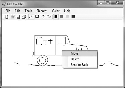
The Send to Back facility ensures that any element can always be highlighted to be moved or deleted; if an element will not highlight, just Send to Back any elements enclosing the element you want to move or delete. In Chapter 19, you will implement the capability to save a sketch in a file.
In this chapter, you've seen how to apply STL collection classes to the problems of managing objects and managing pointers to objects. Collections are a real asset in programming for Windows, because the application data you store in a document often originates in an unstructured and unpredictable way, and you need to be able to traverse the data whenever a view needs to be updated.
You have also seen how to create document data and manage it in a pointer list in the document, and, in the context of the Sketcher application, how the views and the document communicate with each other.
You have improved the view capability in Sketcher in several ways. You've added scrolling to the views using the MFC class CScrollView, and you've introduced a pop-up at the cursor for moving and deleting elements. You have also implemented an element-highlighting feature to provide the user with feedback during the moving or deleting of elements.
CLR Sketcher has most of the features of MFC Sketcher, including drawing operations and a context menu, but you implemented some things a little differently because the characteristics of the CLR are not the same as the characteristics of MFC. The coding effort was considerably less than for MFC Sketcher because of the automatic code generation provided by the Forms Designer capability. The downside of using Forms Designer is that you can't control how the code is organized, and the Form1 class becomes rather unwieldy because of the sheer volume of code in the definition. However, the Class View is a great help in navigating around the class definition.
WHAT YOU LEARNED IN THIS CHAPTER
TOPIC | CONCEPT |
|---|---|
Windows coordinate systems | When you draw in a device context using the MFC, coordinates are in logical units that depend on the mapping mode set. Points in a window that are supplied along with Windows mouse messages are in client coordinates. The two coordinate systems are usually not the same. |
Screen coordinates | Coordinates that define the position of the cursor are in screen coordinates that are measured in pixels relative to the upper-left corner of the screen. |
Converting between coordinate systems | Functions to convert between client coordinates and logical coordinates in an MFC application are available in the |
| Windows requests that a view be redrawn by sending a |
The | You should always do any permanent drawing of a document in the |
Drawing efficiently | You can make your |
Updating multiple views | To get multiple views updated when you change the document contents, you can call the |
Updating efficiently | You can pass information to the |
Context menus | You can display a context menu at the cursor position in an MFC application in response to a right mouse click. This menu is created as a normal pop-up. |
Menus and toolbars in Windows Forms applications | You create menu strips, context menus, and toolbars in a Windows Forms application by dragging the appropriate component from the Toolbox window to the form in the Forms Designer window. You cause the context menu to be displayed on the form in response to a right click by setting the |
Creating event handlers in Windows Forms applications | You create event handlers for a component in a Windows Forms application through the Properties window for the component. You can change the name of the event handler function that is created by changing the value of its |
Controlling what is displayed in a menu | Implementing the |