
Chapter 2
Blink an LED

In the hardware world, the traditional first program most people write makes an LED blink. It’s simple, and who doesn’t like a light show?
The Raspberry Pi’s GPIO headers let you interface with all sorts of hardware. In this chapter, you’ll connect an LED to one of the GPIO pins and learn several ways of controlling it, turning it on and off and changing its brightness. You can even connect a pushbutton and modify what your LED does according to whether the button is pushed.
Hardware Requirements
Here’s a list of what you need for this chapter:
- An LED
- A small resistor. The exact value doesn’t matter; something around 200–500 ohm is best.
- A large resistor, like 10 kΩ–100 kΩ. Again, the exact value doesn’t matter.
I strongly recommended you have the following:
- A solderless breadboard, any size
- A 2×20 pin male header you can solder to the Pi, plus a 2×20 ribbon cable
or
- A 2×20 female header you can solder to the Pi
- Soldering equipment
The following are optional:
- A pushbutton or switch that plugs into your breadboard
- A Pi GPIO extension, like the Adafruit Pi Cobbler or the SparkFun Pi Wedge
What Is GPIO?
Those holes down the side of the Pi Zero W are for general-purpose input/output (GPIO). That’s a way of controlling hardware directly; the Pi can set pins to high or low voltages to control a device, and it can read incoming high or low voltages coming from a sensor.
But first, you’ve got to connect something to the GPIO.
Headers: Hooking Up to the Pi Zero W
The Raspberry Pi Zero W is sold with bare “through-holes” for the GPIO connections, whereas larger Raspberry Pi models have pins. That makes sense—the Pi Zero line is great for hardware control, and someone buying a batch of them might want to solder wires to just a few of those connections rather than using a bulky set of pins. But it makes it a little inconvenient to start playing with your Pi Zero W.
You have several options. The classic choice is to solder a 2×20 male header, like the one shown in Figure 2-1, onto the Pi.
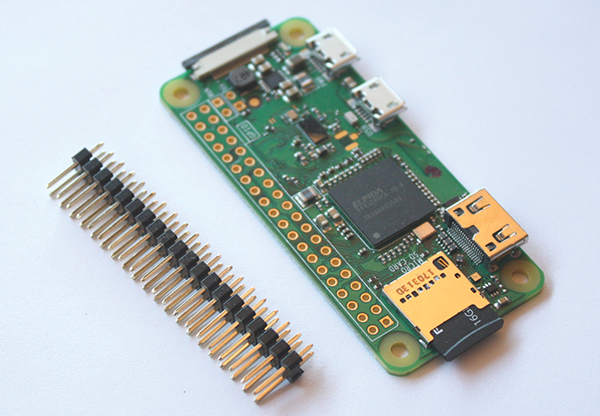
Figure 2-1: A Pi Zero W and male headers, ready to be soldered
A male header makes the Pi Zero W compatible with a wide range of add-ons sold for larger Raspberry Pi models.
If you’re not comfortable with soldering, or if you eventually plan to use your Pi Zero in a very small box where there isn’t room for headers, you could opt for a solderless “hammer header.” These are mostly available from dealers in the United Kingdom, but Adafruit resells them in the United States.
If you use a male header, you’ll need either a 40-wire ribbon cable that plugs into it or a few female-to-male wire leads.
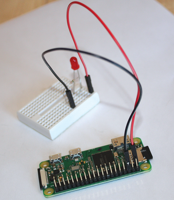
Figure 2-2: Male header with female-to-male leads
You could also choose a female 2×20 pin header. It isn’t as compatible with other Pi hardware, but it makes plugging in wires super easy. You don’t need a ribbon cable or any special wire leads—just regular hook-up wire.
Finally, it is possible to get by temporarily without any soldering to the board if you wedge wires diagonally into the Pi’s through-holes, as shown in Figure 2-3.

Figure 2-3: Look, Ma, no headers!
You can even use headers this way, and if you bend the ends of the wires a little where they emerge underneath the Pi Zero, they might stay in place a little better.
That said, I don’t recommend working this way. The wires won’t make a good connection, and you may waste time debugging projects that don’t work because of a flaky connection. If you’re excited to get started but don’t have any 2×20 headers on hand, go ahead and try it for this chapter, but I highly recommend you order something better before you move on to Chapter 3.
In the hardware list at the beginning of this chapter, I also recommended that you get one of the Raspberry Pi GPIO extensions. These aren’t necessary, but they’re inexpensive and give you an easy way of making the Pi’s GPIO pins accessible on a breadboard. Even better, they include labels reminding you which pin is which. They typically include a ribbon cable that connects the extension to a male header on the Pi.
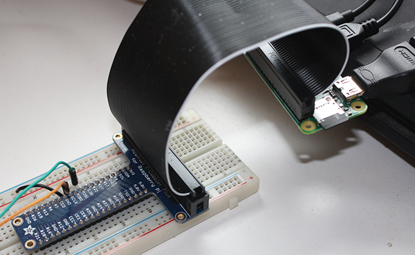
Figure 2-4: A GPIO extension, with ribbon cable and a breadboard
Wiring an LED on a Breadboard
An LED (which stands for light-emitting diode) is an electronics component that can only pass electricity in one direction. So to hook up an LED, you have to know which pin is positive.
Most LEDs have one pin longer than the other. The long pin goes to the positive terminal, whereas the short pin goes to ground. An easy way to remember this is that the “plus” side has had some length added to it.

Figure 2-5: An LED. The long lead is the positive side.
When you wire up an LED, you should always include a resistor in the circuit to limit the current. Otherwise, too much current will flow through the LED and will probably burn it out, with a pop and a little smoke. (Ask me how I know that!)
The smaller the value of the resistor, the brighter the LED will shine. Most small LEDs only need a small resistor, around 200–500 ohms, and it’s generally not critical what exact value you use.
You’ll have to connect the LED to the resistor somehow. You can twist wires together or use alligator clips, but when you’re testing circuits it saves a lot of time to use a solderless breadboard (Figure 2-6).

Figure 2-6: Solderless breadboard. The yellow indicates which holes are connected.
A breadboard has rows of five holes into which you can push wires. Each row of five holes is connected, as indicated by the yellow lines in Figure 2-6. So if you push a lead of the resistor and a lead of the LED into holes in the same row, they’ll make electrical contact.
Some breadboards, like the one pictured, include long strips intended for power and ground connections. When you’re building a circuit, it’s fairly common to have lots of devices that need to connect directly to power and ground, so it’s useful to have the longer strips. By convention, you’d connect the strip marked red to power and the strip marked blue to ground. For the circuits in this book, you won’t need a power or ground strip, so any sort of breadboard is fine.
The Raspberry Pi Pin Layout
The Raspberry Pi’s output pins are numbered starting in the upper left: pin 1 has a pad that’s a square rather than a circle. The pin assignments are fairly chaotic (Figure 2-7)
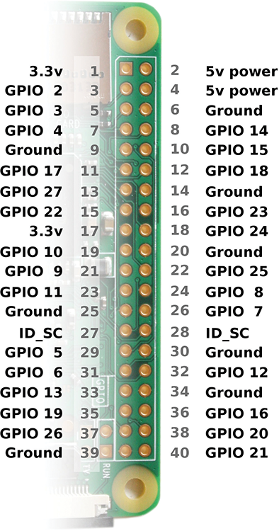
Figure 2-7: The Raspberry Pi’s GPIO pins
So pin 1 is 3.3 volts of power, whereas pin 2 is 5 volts. Pin 3 is called GPIO 2, pin 6 is Ground, and so on to the final pin, 40, or GPIO 21. The GPIO numbers are all out of order and you aren’t expected to remember this crazy layout; you might want to bookmark this page while you work on projects that use GPIO.
A Raspberry Pi can provide 5 volts of power from pins 2 and 4, but its logic circuitry (on the GPIO pins) works at 3.3 volts. If you’re buying hardware you want to drive from a Pi, make sure it can work with 3.3V and doesn’t require 5V. (The 5V pins are provided in case you need to power hardware that needs more than 3.3 volts.)
To test your LED circuit, connect the long lead of the LED to one of the GPIO 3.3V connections, like pin 1. Connect one lead of the resistor to a ground pin, like pin 6. Then connect the short lead of the LED to the other lead of the resistor. See Figure 2-8.

Figure 2-8: LED wired to 3.3V power
The LED should light up.
Controlling an LED from the Command Line
Unplug your LED’s positive lead from the Pi’s pin 1 and connect it to GPIO 14, which is pin 8, the fourth pin in the outer row. Leave your resistor plugged into Ground. Now you’re ready to control the LED from software.
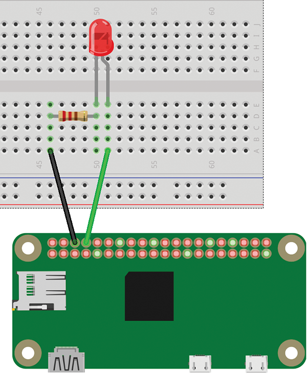
Figure 2-9: An LED hooked up to GPIO 14
You don’t have to write any code to light an LED on a Raspberry Pi. All you need is the raspi-gpio command. In a terminal window connected to your Raspberry Pi, type
raspi-gpio set 14 op dhThe LED should come on.

Figure 2-10: All wired up, using a Pi Cobbler extension
The pin number is 14, and the op (operation) is dh, which stands for “Driving High.”
Now replace that dh with dl for “Driving Low”:
raspi-gpio set 14 op dlThe LED should turn off.
That’s all you need to know about raspi-gpio. But if you want the gory details, you can learn more than you ever wanted by typing
raspi-gpio helpBlinking an LED from the Command Line
The Bash shell is programmable. You wouldn’t want to write a long program in it, but it’s fine for little snippets. Type the following into the shell:
pi@raspberrypi:~ $ while true; do
> raspi-gpio set 14 op dh
> sleep 1
> raspi-gpio set 14 op dl
> sleep 1
> doneYou’ve written your first blinking LED program! First, you tell the Pi to turn on pin 14; then you tell the Pi to “sleep” (that is, not to perform any other commands) for one second. The next lines tell the Pi to turn off pin 14 and sleep for another second. The while true command tells the Pi to loop these commands. The light should blink on and off forever. That was almost too easy.
When you’re tired of watching it, Ctrl-C will kill the program and give you your prompt back. (That’s true of most programs in Linux.)
GPIO from the Command Line via Sysfs
There’s another way to access GPIO from the command line: using an interface called sysfs. Sysfs lets you talk directly to the Linux kernel by writing to and reading from files.
The sysfs interface makes GPIO pins available via files inside the /sys/class/gpio directory (folder). It requires one line of setup for each pin you plan to use:
echo 14 > /sys/class/gpio/exportThe echo command just prints its arguments. Adding > makes it print to a file rather than to the terminal. So this command writes 14 to the file /sys/class/gpio/export. In response, the kernel will create a new directory called /sys/class/gpio/gpio14/, containing several files you can write to control GPIO pin 14.
echo out > /sys/class/gpio/gpio14/directionwrites “out” to the file named direction inside the gpio14 directory you just created. That tells the kernel you want to use that pin as output (you’d use in to use a pin for input).
echo 1 > /sys/class/gpio/gpio14/valueA value of 1 turns pin 14’s voltage high (3.3 volts). The LED should go on. Echo 0 instead of 1 to turn it off again.
Of course, you can use this inside a while true; do loop, just as you did with raspi-gpio:
pi@raspberrypi:~ $ while true; do
> echo 1 > /sys/class/gpio/gpio14/value
> sleep 1
> echo 0 > /sys/class/gpio/gpio14/value
> sleep 1
> done
Blinking an LED from a Python Program
Now it’s time to use a real programming language: Python.
If you’re using the desktop, you can run the IDLE Python development environment by choosing the following:
- Menu > Programming > Python 3 (IDLE)
If you’re using the command line, run the Python shell:
python3Either way, you’ll get a >>> prompt.
Controlling an LED is easy with the GPIOzero library. Type these lines at the >>> Python prompts:
from gpiozero import LED
led = LED(14)
led.on()
You can make that into a blink program, sleeping for half a second between blinks:
from time import sleep
while True:
    led.on()
    sleep(.5)
    led.off()
    sleep(.5)
The spaces beginning each of the last four lines are important; they tell Python that the indented lines are part of the while True loop. It doesn’t matter how many spaces you include as long as you use the same number for all four lines. If you use a different number of spaces, or don’t indent at all, you’ll get an IndentationError. The Python style guide recommends four spaces as being the most readable.
As with the shell, pressing Ctrl-C will stop the program.
Saving Your Program: Text Editors
Of course, you don’t want to have to type your whole program into the Python console every time you run it. You’ll want to save it to a file.
You can’t use a word processor, like Word or LibreOffice, to edit programs. You need something that can edit plain text.
You have plenty of options for text editors on Linux, and Internet flame wars have been fought over which is best (most programmers prefer emacs or vim). If you don’t already have a text editor you favor, try nano if you’re using SSH and the command line. If you’re using the graphical desktop, IDLE has a File > New option with a built-in editor, or you can use Leafpad (Accessories > Text Editor).
Save your LED blinking program to a file with a name like blink.py (you can copy and paste from the lines you typed into the Python console, or from this book’s GitHub repository at https://github.com/akkana/pi-zero-w-book):
from gpiozero import LED
from time import sleep

led = LED(14)

while True:
    led.on()
    sleep(.5)
    led.off()
    sleep(.5)
Save the program (in IDLE or Leafpad, choose File > Save or press Ctrl-S; in nano, press Ctrl-O and then press Enter to confirm the filename). Now run it, either from IDLE’s Run button or from a shell:
python blink.pyand your LED should start blinking.
Fade an LED
The GPIOzero library also lets you set LEDs to partial brightness, using a technique called pulse width modulation, or PWM.
A Raspberry Pi can’t actually set its GPIO pins to anything besides 1 or 0 (3.3 volts or 0 volts). What it can do is pulse the pin (and therefore the LED connected to it) between 1 and 0 rapidly. The more time it spends at 1, the brighter the LED will appear. Fortunately, you don’t have to manage this in your program; you can let GPIOzero’s PWMLED class do it for you.
Instead of creating an LED object with led = LED(14), use PWMLED(14). Then use a variable called value to manage the LED’s brightness, starting at 0 and ramping up to 1, then starting again at 0:
from gpiozero import PWMLED
from time import sleep

led = PWMLED(14)

value = 0
increment = .02
sleeptime = .03

try:
    while True:
        value += increment
        if value > 1:
            value = 0
        led.value = value
        sleep(sleeptime)

except KeyboardInterrupt:
    print("Bye!")
By the way, GPIOzero has fairly good documentation at http://gpiozero.readthedocs.io/. It supports a curious but incomplete collection of hardware, and in some cases it’s hard to tell what hardware is needed to use specific Python classes. If you happen to be using hardware it supports, GPIOzero makes things very easy, but if you’re using anything else, it won’t help you.
With that in mind, it’s good to know something about the more general library that sits underneath GPIOzero: RPi-gpio.
Python Blink Using RPi-gpio
RPi-gpio has been around almost since the first Raspberry Pi, and by now it’s mature and powerful. Using it directly requires a couple of lines of setup beyond that needed for GPIOzero, after which it’s just as easy:
import RPi.GPIO as GPIO
from time import sleep

GPIO.setmode(GPIO.BCM)
GPIO.setup(14, GPIO.OUT)

while True:
    GPIO.output(14, GPIO.HIGH)
    sleep(.5)
    GPIO.output(14, GPIO.LOW)
    sleep(.5)
GPIO.setmode(GPIO.BCM) tells the RPi-gpio library to use the names of the pins. If you’re using GPIO 14, you pass 14 to GPIO.output. BCM stands for BroadCoM, because the pin numbers come from the Broadcom-made chip used in the Raspberry Pi. The library can also use physical pin numbers, if you pass BOARD instead of BCM. If you look at the pin diagram in Figure 2-7, GPIO 14 is on physical pin 8, so this would also have worked:
GPIO.setmode(GPIO.BOARD)
GPIO.setup(8, GPIO.OUT)
GPIO.output(8, GPIO.HIGH)
You may see a warning like blink-rpi-gpio.py:8: RuntimeWarning: This channel is already in use, continuing anyway. Use GPIO.setwarnings(False) to disable warnings. You’d see this warning if the other programs you’ve been running didn’t clean up after themselves. When they stopped using the Pi’s GPIO, they left the GPIO pins active, potentially causing problems for programs that might run later.
Ideally, you should clean up after your program has run, but interrupting it with Ctrl-C makes that more difficult. You could avoid the Ctrl-C by blinking only a fixed number of times, instead of forever:
for i in range(10):
    GPIO.output(14, GPIO.HIGH)
    sleep(.5)
    GPIO.output(14, GPIO.LOW)
    sleep(.5)

GPIO.cleanup()
Note that the GPIO.cleanup() line isn’t indented. That way, Python knows it’s not part of the loop, and it won’t run until the ten blink cycles have finished.
If you want to keep the infinite loop and interrupt it with Ctrl-C as you’ve been doing but still clean up afterward, you could “catch” the interrupt like this:
import RPi.GPIO as GPIO
from time import sleep

GPIO.setmode(GPIO.BCM)
GPIO.setup(14, GPIO.OUT)
try:
    while True:
        GPIO.output(14, GPIO.HIGH)
        sleep(.5)
        GPIO.output(14, GPIO.LOW)
        sleep(.5)

except KeyboardInterrupt:
    GPIO.cleanup()
You could have caught KeyboardInterrupt in your earlier GPIOzero blink program, and GPIOzero would have cleaned up automatically. With GPIOzero, you don’t have to call a cleanup function explicitly; just add pass inside the except section to make sure the keyboard interrupt was caught.
try:
    while True:
        led.on()
        sleep(.5)
        led.off()
        sleep(.5)
except KeyboardInterrupt:
    pass
Python Fade using RPi-gpio
Of course you can fade with RPi-gpio PWM as well. Anything to the right of a # character is a Python comment and not part of the running code.
import RPi.GPIO as GPIO
from time import sleep

GPIO.setmode(GPIO.BCM)

GPIO.setup(14, GPIO.OUT)
pwm = GPIO.PWM(14, 100)     # Set up PWM on pin 14 at 100 Hz

value = 0
pwm.start(value)            # Start at 0
increment = 2               # How smooth is the fade?
sleeptime = .03             # How fast is the fade?

try:
    while True:
        value += increment
        if value > 100:
            value = 0
        pwm.ChangeDutyCycle(value)
        sleep(sleeptime)

except KeyboardInterrupt:
    pwm.stop()
    GPIO.cleanup()
Reading Input: A Pushbutton
You can read input from pins with RPi-gpio as well as set pin values.

Figure 2-11: Wiring an LED plus a pushbutton. Notice that both resistors are tied to Ground on the Pi.
Leave your LED connected, and wire up a pushbutton. If you don’t have a pushbutton handy or can’t find one that plugs into your breadboard, you can fake it using two bare wires that you’ll touch together. That’s really all a pushbutton is.
- Wire one side of the button to pin 1, 3.3v power.
- Wire the other side of the button to pin 10, GPIO 15. Then attach a high-value resistor, like 10 kΩ or more, to that same side of the switch. The other side of the resistor goes to ground.
This is what’s known as a “pull-down” resistor. Without the resistor, when the switch is open, GPIO 15 isn’t connected to anything. It’s not definitely high or definitely low, so if you read its value, there’s no telling what you might see. With the resistor in place, if the switch is open, GPIO is tied to ground through the resistor. But when you push the button (or touch the two wires together if you don’t have a button), it’s much easier for current to flow from the 3.3v pin through the switch to GPIO 15 than to go through that big 10 kΩ resistor. So GPIO 15 reads high.
Now you can read the value at GPIO 15 from Python:
GPIO.setup(15, GPIO.IN)

print("button:" + GPIO.input(buttonpin))
Let’s try doing something with it in the blinking loop. For instance, you could make the LED blink slowly most of the time, but make it blink faster when you press the button.
To make the code a little cleaner, I’ll make variables for the LED pin and the button pin—that makes it easier to change them if you decide to use different pins—and for the sleep durations.
Here’s the program written for GPIOzero:
from gpiozero import LED, Button
from time import sleep

led = LED(14)
button = Button(15)

# Blink times in seconds:
shortblink = .1
longblink = .7

for i in range(100):
    # Set the LED pin to high for odd numbers, low for even.
    if i % 2:
        led.on()
    else:
        led.off()

    if button.is_pressed:
        sleep(shortblink)
    else:
        sleep(longblink)
The program loops 100 times. i % 2 is called a modulo—it divides i by 2 and takes the remainder. So when i is odd, i % 2 will be 1, and the LED will come on. When i is even, i % 2 will be 0 and the LED will turn off.
Then each time around, if the button is pressed, we’ll only sleep for a short time; if the button isn’t pressed, we’ll sleep longer.
Here’s an RPi-gpio version:
import RPi.GPIO as GPIO
from time import sleep

# Use Raspberry Pi board pin numbers:
GPIO.setmode(GPIO.BCM)

ledpin = 14
buttonpin = 15

# Blink times in seconds:
shortblink = .1
longblink = .7

# set up GPIO output channel
GPIO.setup(ledpin, GPIO.OUT)
GPIO.setup(buttonpin, GPIO.IN)

for i in range(100):
    # Set the LED pin to high for odd numbers, low for even.
    if i % 2:
        GPIO.output(ledpin, GPIO.HIGH)
    else:
        GPIO.output(ledpin, GPIO.LOW)

    # Sleep for a short time if the button is pressed, otherwise a long time:
    if GPIO.input(buttonpin):
        sleep(shortblink)
    else:
        sleep(longblink)

# Done: clean up!
GPIO.cleanup()
Other Languages, Other Interfaces
There are lots of options for programming the GPIO on a Raspberry Pi. You’ve already seen a shell script and Python. But if you have another favorite language, don’t despair: you can control the Pi’s GPIO from C or C++, Ruby, Perl, Java, C#, Pascal, BASIC, Gambas (similar to Visual Basic), and even Scratch. There’s no shortage of options!
Now you have the basics of both input and output with the Raspberry Pi’s GPIO. LEDs and switches are simple, but a lot of hardware works pretty much the same way.
But some hardware is more complicated. In Chapters 3 and 4, we’ll take a look at interfacing with other types of hardware, as well as some things you can do with the Zero W’s Wi-Fi capabilities.