Chapter 3: Acquisition of Evidence
Digital evidence is one of the most volatile pieces of evidence an investigator can handle, and the smallest error or mishandling on the investigator's part can severely impact the investigation. You may lose the data forever, or you might lose pieces of it. Unintentional manipulation of data can call your ability to investigate into question, as well as the integrity of the data in the investigation. This chapter will address how to minimize or eliminate any of these issues by using a tool validation process to create an error-free and validated forensic image.
We will cover the following topics in this chapter:
- Exploring evidence
- Understanding the forensic examination environment
- Tool validation
- Creating sterile media
- Defining forensic imaging
Exploring evidence
What is evidence? The dictionary definition is the available body of facts or information indicating whether a belief or proposition is true or valid. Now that seems to be a short, simple, common sense answer to a simple question. In reality, the question becomes far more convoluted when you take into account regulations, the law, and rules of evidence in one jurisdiction, and this grows exponentially when considering multiple jurisdictions. Evidence is a determination made by the trier of fact. The trier of fact will determine if the evidence meets the standards for that proceeding and jurisdiction. Despite the trier of fact, if you accept the evidence, it can still be called into question.
I offer the following example: Let's say you are investigating a murder and you find the victim's and suspect's blood in the suspect's vehicle; the victim's blood on the suspect's socks; and a bloodied glove at the scene, and its matching mate found in the suspect's house.
Based on this evidence, you could believe the government had an airtight case against the suspect. But in this case, the defense was able to successfully argue and challenge the evidence, which resulted in the suspect's acquittal. As you can see, just because something is evidence, if it cannot withstand the challenge of the opposition, then it becomes a liability.
I have worked on both sides of the judicial process regarding digital evidence, and every time, the sheer amount of digital evidence that never sees the light of day amazes me. If the evidence is not presented to the trier of fact and accepted, it does not exist as far as the proceedings are concerned. Neither side will reference it or offer it during the proceedings. It simply will not exist.
How does the opposition attack evidence that has been admitted by the trier of fact? Either by attacking the evidence itself and/or by attacking the process and personnel associated with the collection and analysis of the evidence.
Consider the following example:
An examiner analyzes the thumb cache of the system and sees a URI (The URI is a uniform resource identifier based on the standard created by the internet engineering task force. In this instance, it is the file path.) pointing to the location of the original image. The original destination folder no longer exists on the system, nor does the source image for the thumbnail in the cache.
As shown in the following screenshot, the source image for the thumbnail in the cache was located in the New folder on the Picture Drive of the user account of bob. This is the URI that was found in the thumbnail's metadata:
Figure 3.1 – URI image
In the following screenshot, you can see the URI that was found in the metadata of a different thumbnail in the same thumb cache. The path is very similar to the one found in the URI image. There are significant differences here – the user account is bobby, not bob, and the New folder does not exist:
Figure 3.2 – URI image: bobby
On the system that was being analyzed, there was not a bob user account, nor were there any artifacts showing the bob account was ever created or deleted from that system. The digital forensic examiner amended their report and incorrectly stated the Picture Drive was the same in both instances based on the similarities of the URIs. Originally, the digital forensic examiner stated, The URIs found within the metadata represent file paths that cannot be verified.
The digital forensic examiner conducted a second exam and found a deleted folder called New on the Picture Drive and amended the report to reflect The URIs found within the metadata represent evidence item HDD 001. The New folder was deleted on this date and time. (I am not utilizing exact names or dates for obvious reasons.)
Based on the file path and the current users, there was no way to determine if the New folder referenced in the URI was the same as the deleted New folder. When the digital forensic examiner was confronted about these discrepancies, they admitted that they had made an error. I believe they made the error because of the similarities of the file paths and not paying attention to the specific details. I absolutely believe the error was not malicious or intentional but an honest mistake by the opposition's digital forensic examiner. As you can see, sometimes, an honest mistake can lead to additional questions being asked about the collection of the evidence and the process used to generate the report and the evidence.
In a different case I was brought in on, the suspect was charged with attempting to lure a child. In this specific set of circumstances, the suspect was communicating with an undercover agent (UC) and sent many illicit images to the UC. When the subject was taken into custody, they were interrogated, confessed, and wrote an apology letter. The confession, over 400 pages of chats, and a dozen illicit images submitted as evidence in the judicial proceedings. Once again, you would expect that there would be a conviction based upon this evidence.
During the trial, it was revealed the government had deleted some text messages and edited the video file of the recording of the confession. The judicial authority informed the jury of the manipulated evidence and that the only conclusion they could consider was that the alteration of the digital evidence was done in a manner to hide facts that would hinder the government's prosecution. The jury then found the subject not guilty of all charges.
If you do not follow the best practices, policies, and procedures of your organization, the evidence will not see the inside of the courtroom and if it is admitted, the opposition's attacks will mitigate its effectiveness. These attacks can create enough reasonable doubt to generate an acquittal.
So, what can we do to mitigate the attack of the opposition? It does not matter which side of the matter you are on; the opposing counsel will attack your findings if it is harmful to their case.
Do not forgo proper evidence handling procedures. Proper evidence handling does not end with the collection of evidence in the field. As it is being transported from the field to the secure location, and whenever someone checks out the evidence, you must ensure the chain of custody and security of the evidence is maintained.
Do not forgo utilizing proper procedures, methodologies, or processes when conducting your digital forensic investigation. Do not take shortcuts.
Validate any procedure, methodology, or process. You have to go through the validation process; you cannot rely on third parties to do the validation for you. Your validation has to repeatedly reproduce the same results when performed by you or anyone else.
If you prepare and conduct your digital forensic examination with the mindset that someone will go through every step you take and question every finding you make, you should be able to mitigate any attack against your digital forensic examination. The key is that you have to prepare. If you are unprepared for the attack, then you may be made to look incompetent while testifying in the judicial/administrative proceedings.
We have discussed the evidence, but what about the environment you will conduct the investigation in? We will now discuss how you should control the examination environment.
Understanding the forensic examination environment
A term that has been pounded into my head since I first went to training with IACIS is the Forensically Sound Examination Environment. While it sounds complicated, it is a relatively simple concept:
- The digital forensic examiner controls the working environment of the digital forensic examination.
- No actions will occur unless the digital forensic examiner intends the action to occur.
- When the action has been completed, the examiner will reasonably know what the expected outcome is.
This concept does not merely apply to a physical location, but anywhere we complete a digital forensic examination or perform actions to support the digital forensic investigation. This could be a lab, office, or in the field where the digital evidence has been collected.
The Forensically Sound Examination Environment is a mindset of the digital forensic examiner. You want to be methodical and thorough as you perform any action to support the digital forensic examination. With this mindset, it will eliminate some mistakes that may occur during the process.
For example, the organization sent two colleagues to a remote location to acquire several workstations. They were able to complete the acquisition of data within 2 to 3 days. No triage or examination was done on the scene, but it was expected to be completed when they returned to the central lab. The remote location was several hundred miles away, and once my colleagues left, they could not return to gain access to the source devices. Upon arrival at the central lab, my colleagues started to conduct their digital forensic examination. Colleague A started to examine one of the forensic images, and as a part of their process, they viewed the folder structure of the filesystem. As they were looking at the installed programs, they were shocked to find a commercial forensic tool installed on the suspects' system. As they drilled down further into the filesystem, they started to find documents with their name on it. They were shocked; how did the suspect gain access to Colleague A's information? The suspect didn't.
Colleague A made an error when creating a forensic image. Instead of imaging the suspects' device, they imaged the system drive of their forensic laptop. They ignored the details as they were creating a forensic image. Luckily, the procedure was for each colleague to make a forensic image of the source device, for a total of two forensic images.
While this story is embarrassing, there were no lasting repercussions because we could use the second copy. Imagine how you would feel if you were Colleague A, and there was not a second backup to use. How do you explain to your supervisor or the client that you could not complete the task as given, and now you do not have access to the source device?
To help stop that from occurring, we will look at tool validation.
Tool validation
Earlier, we discussed potential attacks on you, your exam, and your findings. The opposing counsel will focus on how you did the exam and what tools you used to perform the exam. Your ability to mitigate the opposing counsel attacks is directly related to your preparation and the documentation you created during the exam. Being aware and following best practices is critical in your ability to successfully defend your actions. How do you do this? By continuing your education. The field is always changing, and you have to keep aware of those changes.
The level of detail can easily overwhelm new digital forensic investigators as they need to know how to mitigate the opposing counsel's attack successfully. While you need not know the specific programming or code a particular tool uses, you need to know where the artifact found by the tool is located within the filesystem/operating system so you can adequately explain it as you testify or create your report. Many times, I have seen an examiner rely on a checklist provided by a colleague or one they found on the internet and yet have little to no understanding of why the items are on the checklist or the process used to recover the artifact. It can be as simple as recovering a deleted file. If the digital forensic investigator cannot explain the process of how the specific filesystem processes the user's request to delete a file and how the tool recovered the deleted file, their time testifying will be very uncomfortable. If you cannot explain the basics, all of your findings will be called into question.
You need to determine if your tools produce a valid result. As we saw in our previous discussion in Chapter 2, The Forensic Analysis Process, in the matter of Casey Anthony the opposing counsel was successful in mitigating the digital evidence because of an error reported by the forensic tool. If the forensic tool has been found faulty, then the use of the tool may be used as a means to discredit the integrity of the exam and the competence of the examiner.
How do you mitigate the attacks on your process or your tools?
- Understand their functionality
- Document your training
- Take notes during the exam
- Validate the tools
Your testimony about your exam, your findings, and the use of the tools is based on your personal experiences. You cannot testify about someone else's validation. You do not know all the parameters the third party used or did not apply. This is something you have to do personally. Use the tool against a known dataset to see if it performs as expected. If you do not validate your forensic tool, how can you testify that it is providing an accurate result? If you get questioned on the stand, how do you answer the question? It is not uncommon for the opposing counsel to recreate the forensic exam you did. The opposition will attempt to use the same forensic process and the same forensic tools to determine if they can get the same result. What happens if they get a different result using the same method and the same tools? What happens if they get a different result using the same process and different tools? If you do not validate your processes and forensic tools, how can you prepare for that attack against yourself or your examination?
As we mentioned earlier, NIST has created the Computer Forensic Reference Data Set. You can follow this link to assist you in validating your tools: https://www.cfreds.nist.gov. These datasets provide an investigator with documented sets of simulated digital evidence for examination. NIST has also provided resources for the creation of your test images.
We can use these datasets in a variety of ways:
- Validation testing
- Proficiency testing
- Training
If you use your dataset or a dataset from a third party, you must ensure there is documentation on what is in the dataset and where the testing data is located within the dataset. In the following example, we will use the DCFL control image provided by NIST.
In this example, we will use two forensic tools: the open source tool Autopsy and the commercial tool X-Ways. As shown in the following screenshot, the documentation states there should be two logical files:

Figure 3.3 – DCFL control image
The documentation provides us with the logical filename and extension, the hexadecimal offset, and the MD5 hash value for the file. (Remember that the hash value is the digital fingerprint of the file.)
In the following screenshot, we are looking at the interface of Autopsy, which shows that there are two logical files (identified by file extension): one image file and one audio file. So far, that matches the documentation we have been given for the control image:

Figure 3.4 – DCFL control image 2
In the following screenshot, we are looking at the interface of X-Ways, and it has also identified two logical files, whose filenames match the control:

Figure 3.5 – DCFL control image 3
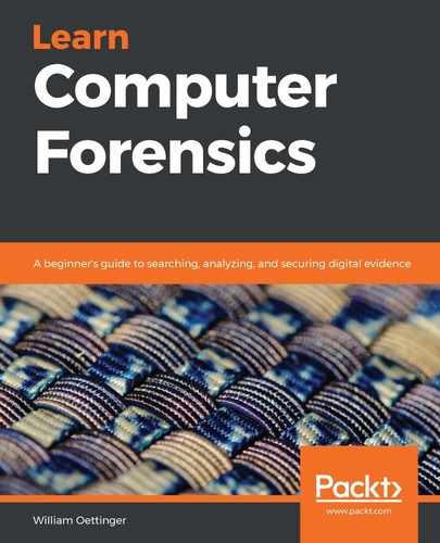
In the following screenshot, we are looking at the metadata of the image file as provided by Autopsy, and we can see that the filename, extension, and hash values match the information provided in the control documents:
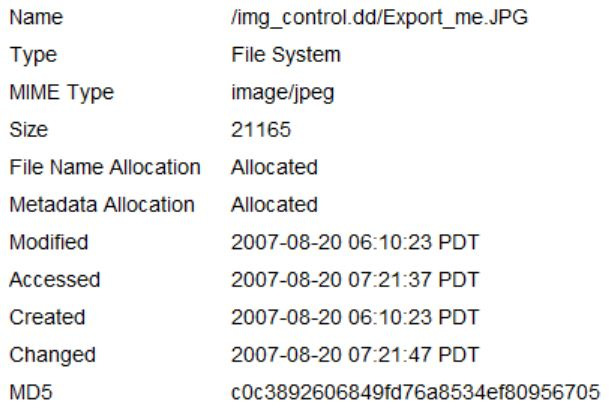
Figure 3.6 – DCFL control image 4
In the following screenshot, we are looking at the metadata for the same file in the X-Ways interface, and find it also matches the information provided in the control documents:

Figure 3.7 – DCFL control image 5
You will work your way through the rest of the control image to ensure the forensic tool of choice is functioning correctly and is producing accurate results. There are multiple control datasets you can use to validate your tools. You cannot be sure your tool works properly until you conduct the validation test. Your organization should have a policy dictating when the validation should occur and how to document and record the results of the validation test. If you do not log the validation tests, the opposing counsel can call it into question when they request those records.
That covers the validation of your tools, but what about the storage containers? Let's discuss sterile media and define what it is.
Creating sterile media
Sterile media is also a concept that was emphasized when I first trained. Now, there is a discussion regarding whether sterile media is still needed in today's forensic environment. The decision to use sterile media to store the forensic data will be based on the acquisition and the type of examination you will use. Sterile media can be used before the start of the forensic process and at the end of the forensic process. There are multiple reasons to use sterile media, which we will now discuss. When digital forensics was first starting, we did not have the capability to create a forensic image; we were forced to create a forensic copy to perform our examination on. Remember, we talked about a forensic copy in Chapter 2, The Forensic Analysis Process, and defined a forensic copy as follows:
"A straight bit-for-bit copy of the source to the destination. This is not common in today's environment; ensure that your destination device has no old data from previous investigations. You do not want to cause cross-contamination between the current digital forensic investigation and a past investigation. We will recover deleted files, file slack, and partition slack."
If your source and destination were the same make, model, and capacity, then you would potentially not have an issue. In real life, this rarely happens, so you would use a larger capacity device and you would copy the data from the source device to the destination device. As a result, you would have unallocated space not used on the destination device. If you did not wipe or use sterilized media as your destination device, it is possible that there would be pre-existing data on your destination device, and this creates the possibility for the co-mingling of data. So, when using the forensic copy process and you look for data in unallocated space or slack space, you must use sterilized media.
There have been cases where the examiner has used a newly purchased storage device or had the storage device provided to them; they still must wipe the drive and sterilize it of all pre-existing data. If you do not and the destination device is provided to the opposing counsel and they find data not relevant to the matter at hand, it can call into question the integrity of the exam and the competence of the examiner.
What do you do with old storage devices that contained digital evidence? Do you destroy them? Do you recycle them? Do you turn them over to your organization and not worry about it? Before the storage device leaves your control, you must wipe that device to ensure no confidential information or contraband is released to an unauthorized entity. That way, you can be positive that there is no way data relating to any digital forensic exam can be released without your approval.
So, what exactly is sterile media? It is simply where every byte on the device is overwritten with a hexadecimal 00. Technically, you can use any character you like, but it is much easier to verify whether the sterilization of media was successful if you use the hexadecimal 00. We use the 64-bit checksum to validate the sterilization process. If you run the 64-bit checksum against the sterile media, you will get zeros as the generated checksum value. I do not recommend using the MD5 or SHA–1 hashing algorithms to verify the sterilization process. They will not give you a value you can use to immediately identify the successful sterilization process.
Let's look at the sterilization process. We will use Paladin from Sumuri Forensics. Paladin is a live bootable version of Ubuntu. This means you have to have Paladin installed on a USB or a DVD/CD. Using a USB or CD/DVD will allow the computer to boot to the operating system contained on the USB/CD/DVD. Paladin allows you to access the host computer while modifying none of the digital evidence. The Paladin toolbox allows us to create forensic images, convert forensic images, and create sterile media.
In the following screenshot, I have opened the Paladin toolbox and selected Disk Manager:

Figure 3.8 – Paladin toolbox
As we look at the preceding screenshot, we see that there are three devices on the system: two 10-GB hard drives and a CD-ROM drive. The CD-ROM is the Paladin operating system, while the two hard drives are the storage drives on the computer. We will wipe one of these storage drives, in this case, /dev/sdb. As you look at the interface, below the device listing, you will see a variety of options. At the far right, we have a button titled Wipe. This is the button we will select after we left-click on the device we want to wipe. You do not want to mount the device before wiping it.
Once Paladin has completed the wiping/sterilization process, it will show you a log of the processes being used. In the following screenshot, we can see that it input the pattern 00 and the number of sectors that were overwritten. The last line tells us when the operation was completed. You need to save this log and store it with the storage device you have just wiped:

Figure 3.9 – Paladin toolbox 2
But how do we verify the results to ensure the tool works as expected? Here, we will use the commercial tool X-Ways Forensics. X-Ways Forensics is a commercial tool offered by X-Ways Software Technology AG and is my go-to tool when conducting a digital forensic exam. Its ease of installation, price, and the ability to use it on many platforms are what I find attractive about this tool. It's not that other tools are not worthwhile; this is just my personal preference.
We have added the device into X-Ways, and now we want to verify the sterilization process we used with Paladin. Follow these steps to do so:
- Right-click on the device and select Properties:

Figure 3.10 – X-Ways 1
- The Properties window of the device will appear. Toward the bottom right, you will find the Compute hash button. When we left-click it, we will see the hashing options available to us:

Figure 3.11 – X-Ways 2
- You will want to select Checksum (64 bit), which will return zeros if the sterilization process worked correctly:

Figure 3.12 – X-Ways 3
If you choose MD5, SHA–1, or any other hashing algorithm, you will get a value for the device, but that value will not let you determine if there is any residual data left on the device.
- As shown in the following screenshot, the checksum result is a string of zeros. This informs us that the media sterilization process has worked correctly. We have also just validated another aspect of our forensic tools:

Figure 3.13 – X-Ways 4
We now have sterile media, but how do we protect the original evidence? The answer is to perform write blocking, which we will discuss next.
Understanding write blocking
Write blocking is at the core of the forensic examination environment. With the fragility of digital evidence, we want to ensure we do not change a single bit of data on the source device. Evidence handling is an essential function of the examination process, and we must ensure that we meet all the requirements to avoid altering or damaging the evidence. If I plug the device into a Windows-based computer system, to enhance the user's experience, the operating system scans and makes writes on that device that change the evidence. To prevent the alteration of the source device, we must use a write blocker.
You have a choice of utilizing a "hardware write blocker" or a "software write blocker."
Hardware write blocker
As the operating system issues commands, it will read/write from the source device. A hardware write blocker is a device that intercepts and prevents any modification to the source device. It is physically connected between the computer and the source device to accomplish this. There are also standalone hardware write blockers that are self-contained that allow you to attach the source and destination device and then create the forensic image.
In the following image, we can see the Tableau Forensic SATA/IDE Forensic bridge T35u that the Department of Homeland Security tested in October 2018. This device allows you to forensically acquire SATA and IDE devices by using the computer's USB 3.0 connection:

Figure 3.14 – Tableau
NIST has created the Computer Forensics Tool Testing Program, which lists the testing results for hardware write blockers (https://www.nist.gov/itl/ssd/software-quality-group/computer-forensics-tool-testing-program-cftt/cftt-technical/hardware). Here, you can find the report on the T35u and other devices.
Software write blocker
Software write blocking is where a change is made to the operating system to stop it from making writes to the device. For a Windows-based system, there is a registry change you can make to prevent rights to attached USB devices. This will require you to have a hard drive dock to connect to the system.
Another option is to utilize a bootable operating system, such as Paladin or Win FE.
In the following screenshot, we can see the Paladin toolbox, and it is listing the drives in the system. By default, Paladin mounts none of the attached storage devices. This means it makes no modifications and doesn't look at the devices until you tell the software to mount:

Figure 3.15 – Paladin toolbox
There are two options when you mount a device:
- Read-only
- Read/write
You should not mount a device read/write unless you want to change the device. If you create a forensic image of the device, then you should mount read-only.
As shown in the following screenshot, there is a column listed as Mode, and we can see that the CD-ROM is mounted as read/write and is highlighted in red, while the hard disk is green and shows read-only:

Figure 3.16 – Paladin toolbox 2
Now that we have protected the source device with the original evidence, let's move on to creating the forensic image.
Defining forensic imaging
I continue to stress that we never want to change the source device/digital evidence. That is why we never conduct a digital forensic examination on the original device. You should only conduct your digital forensic analysis on a copy and not the original. You must remember the forensic copy you make will also be considered the evidence and will have the same evidentiary weight as the original source device in terms of evidence. What are we transferring from the source device into our forensic copy? Everything! I want to look at allocated files, deleted files, slack space, unallocated space, and unpartitioned space. I want to collect every bit on the source device. Earlier in this book, in Chapter 2, The Forensic Analysis Process, I gave you the following definitions:
- Forensic copy: This is a straight bit-for-bit copy of the source to the destination. This is not common in today's environment, so ensure that your destination device has no old data from previous investigations. You do not want to cause cross-contamination between the current digital forensic investigation and a past investigation. We will recover deleted files, file slack, and partition slack. We will discuss wiping hard drives later on in this book.
- Forensic image: We are creating a bit-for-bit copy of the source device, but we store that data in a forensic image format. This could be a DD image, an E01 image, or an AFF image. We take that source data and wrap it in a protective wrapper of the forensic image. We will recover deleted files, file slack, and partition slack.
- Logical forensic image: Sometimes, we are restricted to only accessing specific datasets. They do not allow us to access the entire container. We cannot create a bit-for-bit copy of a forensic image or a forensic copy. This could be when we are extracting data from a server, and we cannot shut the server down to create a forensic image from the source hard drives. Due to this, we can make logical copies of the files and folders pertinent to the investigation. We will NOT be able to recover deleted files, file slack, and partition slack.
For the forensic copy and the forensic image, we will acquire every bit on the source device; if there are restrictions, then we will only be able to copy the logical files. We will then put the logical files into a forensic container, which will then encapsulate them in a protective format to prevent any alteration to the data after we've collected it. These are not backups, as you might see in the corporate environment. In the corporate environment, they have not created those backups in a forensically sound manner and they will not contain any information about file slack, unallocated space, deleted files, or any piece of data that is not maintained by the filesystem. I do not recommend doing digital forensic examinations in which commercial/open source backup software was used to collect the evidence. Only use a trusted and verified forensic tool that will collect all the information, and do so in a forensically sound manner.
There are two common formats for a forensic image. (There are others, but DD and E01 are the two formats I consistently see used by government and corporate digital forensic investigators.) Let's take a look at them now.
DD image
DD is a UNIX command, and some call it the oldest imaging tool available that has migrated to other platforms. You can find versions of DD that work on Linux, Windows, or Mac and they all work in relatively the same manner. They designed it to copy data from a source device to a destination device. Relatively simple, is it not?
With a DD image, you can do a forensic copy, which is every byte from the source device to the destination device. You also have the option of creating a flat-file/RAW image of the source device. The image file can be a single file, or we can segment it into multiple pieces. It does not compress the forensic image, so you must ensure that your destination device is of the same capacity or greater than the source device.
In the following screenshot, you can see an example of a DD image that has not been segmented and is 21 GB in size. Depending on the format of your storage device, you may have to segment the forensic image to meet the filesystem's constraints. You may also see different file extensions for the DD image;.001, .dd, and .img are common file extensions:

dcfldd (http://dcfldd.sourceforge.net/) is a version of the dd command that has incorporated additional features, such as the following:
- Hashing on the fly
- Status output
- Disk wiping
- Verifying an image or wipe
- Multiple outputs
- Splitting outputs
- Piped output and logs
dcfldd was written by Nick Harbor (former employee of DCFL).
Note
dcfldd has an issue with imaging faulty drives. NIST reported that dcfldd will misalign the data in the image after a faulty sector is encountered on the source device. You can visit this link to find out more: https://www.dhs.gov/sites/default/files/publications/DCFLDD%201%203%204-1%20Test%20Report_updated.pdf.
dc3dd (https://sourceforge.net/projects/dc3dd/) is another version of the dd command. Where dcfldd is a fork of the dd command, dc3dd is a patch of the dd command. While these options are similar, they have a slightly different code base and feature sets. When the dd command is updated, dc3dd is also automatically updated.
Some features available on dc3dd include the following:
- Ability to have on-the-fly hashing
- Ability to write errors directly to the file
- Ability to create error log pattern wiping
- Ability to verify mode
- Ability to create progress reports
- Ability to split outputs
Jesse Kornblum developed dc3dd at the DoD Cybercrime Center. The next format we will discuss is the EnCase evidence file.
EnCase evidence file
The other forensic image format we will talk about is the EnCase evidence file, commonly referred to as e01 or the expert witness file format. Where the dd command is a direct bit-for-bit copy, the e01 format is also a bit-for-bit copy, but includes additional data within the forensic image.
EnCase Forensics is a commercial forensic tool created by Guidance Software (now Open Text) and was one of the first commercial digital forensic tools available for use. They created the forensic image file known as the e01 format, Expert Witness Format (EWF), or the EnCase image file format.
The e01 file format is a forensic image that encapsulates the raw data from the source device to prevent changes from occurring after acquisition without informing the user about the changes. While the dd image only contains the data from the source device, the e01 forensic image contains header information such as evidence name/number, acquisition dates and times, investigator notes, and information about the forensic tool used to create the forensic image. The e01 forensic image also has additional security features to ensure the validity of the forensic image. There is a CRC calculation every 64 sectors as the forensic image file is created. It stores the CRC value within the forensic image so that every time the forensic image is utilized, your forensic tool can verify it.
As seen in the following screenshot, you can see the layout of the e01 file format. The Case Information is at the head of the file, a CRC is created from the header information, and then a 64-sector block is added to the image file and a CRC value is created for that 64-sector block and added to the forensic image. The data block and the corresponding CRC block process continues until it acquires the entire source device. Once the process has reached the end of the source device, an MD5 hash value is generated of all the data blocks (and only the data blocks) and attached to the end of the forensic image. With the e01 forensic image, you also can enable compression; you do not have that ability with a dd image:

Figure 3.18 – e01
Next, we need to discuss SSD drives, because SSD devices have some special considerations when it comes to imaging.
SSD device
Solid State Storage (SSD) is a new type of storage device that is becoming more prevalent in the business and consumer market. As the price of storage devices comes down, their use will increase. SSDs create a unique issue regarding digital forensics. There are automated processes that are run through the firmware of the device. The digital forensic examiner has no way to stop or to intercept the commands of the firmware on the storage device. Wear leveling is a feature that ensures the storage blocks on the device are used at a similar rate. If some blocks on the storage device are overused or if the blocks are not equal, it can lead to premature failure of some storage blocks. The firmware will decide on where to move the data on the storage device. Plugging in the solid state device can cause the firmware to move data around.
Garbage collection is the other firmware function that causes concern in the digital forensic world. When a user deletes a file, formats a partition, or deletes partitions, the firmware starts the garbage collection process with the trim command. This causes the now unallocated space to be wiped, and the deleted data will no longer be accessible.
It is possible that after you create the forensic image of the source device and you have your pre- and post- hash values of the source device, if you go back days, weeks, or months later and hash the source device, it may come back with a different hash value. It also may also be possible with large drives with long imaging times that the pre- and post- imaging hash values do not match, depending on how much "idle time" the drive has during the imaging process.
As long as you are able to explain the issues with SSD drives, you should have no issues, so we will move on to imaging tools.
Imaging tools
Remember that you do not want to conduct your investigation on the original media, especially SSD devices. As I mentioned in the prior section, the wear leveling and trim commands will result in a change in the original evidence. There are many forensic tools for you to use for your imaging needs; we will now discuss two freely available tools and how to create a forensic image.
FTK Imager
FTK Imager is a free tool offered by AccessData. You can visit https://accessdata.com/product-download/ftk-imager-version-4.2.0, which will help you create a hash value for the source device, image it, and then create the post hash value to verify that no changes were made to the source device during the imaging process:

Figure 3.19 – FTK Imager
After using the appropriate write blocker, we attached a 2-GB USB thumb drive to the system. We will now obtain the pre-hash of the device. This hash value gives us the starting value of the device. This value will be used to determine if any alterations have occurred on the source device. In the preceding screenshot, you can see we have loaded the physical device into FTK Imager and then right-clicked to bring up the Verify Drive/Image menu. Simply click on Verify Drive/Image and let FTK Imager do its work. The results will be displayed after, as shown in the following screenshot:

Figure 3.20 – FTK Imager 2
Now that we know what the starting hash value is, we can proceed with the creation of the forensic image:

Figure 3.21 – FTK Imager 3
As shown in the preceding screenshot, click on the File menu and select Create Disk Image.
From here, you will select your source. With FTK Imager, we have some choices to make:
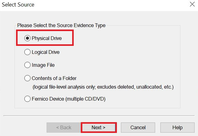
Figure 3.22 – FTK Imager 4
Let's discuss each option in detail:
- Physical Drive: The physical device will give us every bit of data on the source.
- Logical Drive: You will only get the data within the partition boundaries. If there are deleted partitions or data outside of the boundaries on the source device, you will not be able to recover that data.
- Image File: If you want to change the format of the forensic image; for example, change it from an e01 to a dd image.
- Contents of a Folder: You will only get the logical data. You will not get deleted data or unallocated space. Sometimes, you may not be able to shut the system down to create a physical image, such as a server, so you have to grab the logical files for analysis.
- Fernico Device: Use this option if you have a Fernico FAR system.
Since we want to get all of the data on the device, we will select Physical Drive:
Figure 3.23 – FTK Imager 5
You will then be presented with the Select Drive dialog. In the preceding screenshot, there are a lot of physical drives being presented, so you have to careful that you select the correct device!
Note
You can use Windows (or your OS of choice) disk manager to get the physical device number.
We want to select physical device 12, which is the Kingston Data Traveler:
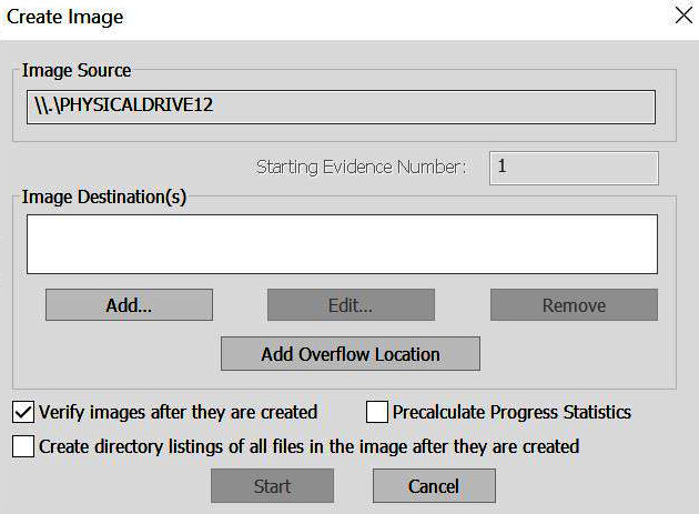
Figure 3.24 – FTK Imager 6
Now, left-click on the Add button to select where you want to save the forensic image and what kind of forensic image you wish to create:
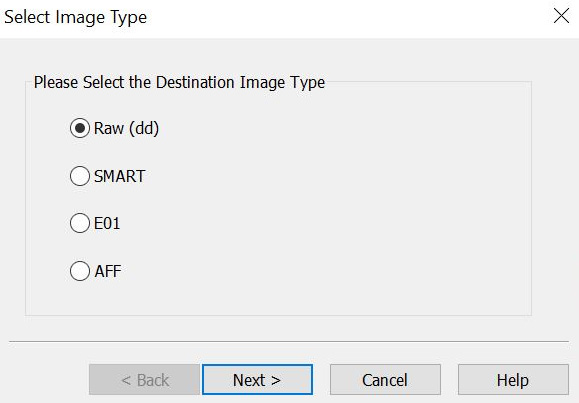
Figure 3.25 – FTK Imager 7
What kind of forensic image do you want to create? You have the choice of four options:
- Raw (dd)
- SMART
- E01
- AFF
We have already discussed the two most common formats: dd and e01. You can also create two other types of forensic images:
- SMART: SMART forensics is a commercial forensic tool on the Linux platform offered by ASR that can be found at http://www.asrdata.com. It can create compressed or uncompressed forensic images and has the ability to segment forensic images.
- AFF: Advanced Forensics Format (AFF) is an open source format for the creation of forensic images. The goal of the designers was to create a nonproprietary forensic imaging format. Simson Garfinkel and Basis Technology originally developed AFF.
I do not recall creating a forensic image that was not in the EnCase format or a dd image. My preference is to create a dd image because it is faster than creating an e01 forensic image. Once the examination is complete, I convert the dd image into the e01 format with high compression to help reduce the file size.
Once you've selected the forensic image format, you will be asked to enter the evidence item information (as shown in the following screenshot), which comprises the following:

Figure 3.26 – FTK Imager 8
Let's discuss each option in detail:
- Case number: This should be the overall identifier for the investigation.
- Evidence number: This should be an identifier to help you track the digital evidence. If you have an extensive investigation with multiple source devices, this will help you accurately identify what forensic image you are working on.
- Unique description: This is where I would add the make, model, capacity, and serial number of the source device.
- Notes: This is where I would add some specific details about where the source device came from, such as a laptop, desktop, and so on.
Your next option is to select the destination (as shown in the following screenshot) for the forensic image in the image destination folder. This could be a storage device attached to the local computer, a connected RAID device, or a form of network-attached storage (NAS):

Figure 3.27 – FTK Imager 9
Next, you need to make a selection regarding filing. I recommend using a similar identifier as the evidence number to help avoid confusion.
Image Fragmentation Size will come into play, depending on the filesystem on the storage device and how you will archive the data. In the past, I used a 2 GB fragment size to ensure the forensic image could be used with multiple filesystems. If I do not expect the forensic image to leave my environment, then I will not use a fragmented image. Just know which filesystems have a file size limitation.
I rarely use compression because of the increase in time used to create the forensic image.
Your last option is to encrypt the forensic image. If you encrypt the forensic image, make sure you use a password you will not forget. If you forget the password, you cannot use the forensic image.
Once you have completed answering the requested information, as depicted in the preceding screenshot, you will see the Create Image window, showing the options you have selected. You also have the option to add a second destination to create two forensic images at a time:

Figure 3.28 – FTK Imager 10
Once FTK Imager has completed creating the forensic image, it will provide you with a status update showing the elapsed time:

Figure 3.29 – FTK Imager 11
This will also show you the results window, as shown in the following screenshot (a text file is also automatically created and stored in the same location as the forensic image):
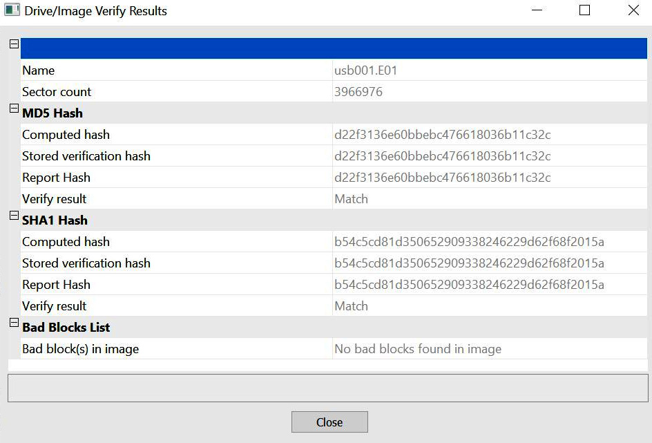
Figure 3.30 – FTK Imager 12
FTK Imager is not the only tool you can use to create a forensic image. An open source forensic tool you can use is Paladin. Paladin has many features, but we will only discuss how it creates a forensic image here.
Paladin
Sumuri's Paladin is a Linux distribution based on Ubuntu that allows the collection of digital evidence in a forensically sound manner. The following screenshot shows the desktop you will see when you boot up Paladin:

Figure 3.31 – Paladin 1
To create a forensic image with Paladin, we will follow the same general steps that we did for FTK imager, with the exception that we do not have to use a hardware write blocker. Paladin is a live distribution of Ubuntu, so you will have to boot your computer to either a USB device or a CD/DVD. Once you see the desktop shown in the preceding screenshot, you are ready to start imaging:
- Left-click on the Paladin toolbox icon to get started.
- Once the Paladin toolbox opens, left-click on Disk Manager (as shown in the following screenshot) to see what devices are attached to the system. You will see there are three SATA devices on the system:
SDA–20-GB hard drive.
SDB–256-GB thumb drive with one partition (sdb1).
SDC–2-GB thumb drive. All three devices are represented in black text.
- Once you've mounted the device, the text will change to green for read-only access and to red for read/write access:

Figure 3.32 – Paladin 2
- Before starting the forensic imaging process, we must pre-hash the source device. Just select the source device and then click the Verify button while in Disk Manager. You will see the output shown in the following screenshot:

Figure 3.33 – Paladin 3
- In the following screenshot, you now have the option to choose the source device, the forensic image you want to create, and the destination location:

Figure 3.34 – Paladin 4
- When you select the dropdown for the source device, you will see a list of devices recognized by the system. This is the same list of devices we saw in the Device Manager. It is essential to choose the correct device when creating your forensic image. Here, we will select the sdc device:

Figure 3.35 – Paladin 5
- When you select the image format drop-down menu, you will be presented with more choices. We have discussed dd, e01, and SMART forensic images, so let's consider the remaining options shown in the following screenshot:

Figure 3.36 – Paladin 6
Let's discuss them in detail:
ex01: This is an updated format of the e01 forensic image. It was introduced with the release of EnCase 7.
Dmg: This is a proprietary Apple disk image file. It is considered to be a RAW forensic image.
vmdk: VMware Virtual Disk Format. This is a virtualization disk image.
vhd: Virtual Hard Disk. This is a virtual hard disk format typically used by Microsoft Virtual PC, Virtual Server, and Hyper V Server.
- Your next option is to select the destination. With Paladin, you must ensure the destination device is mounted read/write. I have ensured that sdb1 has been mounted read/write and has sufficient capacity to store the forensic image:

Figure 3.37 – Paladin 7
- All that remains is to add a label, that is, a filename. I recommend using the same naming convention to identify the different pieces of evidence. Since it is a USB device and it is the first device I have imaged, I will label it usb001:

Figure 3.38 – Paladin 8
You also have the option to Verify after creation and whether you want to create a forensic image with segments.
You also have the option to create a second forensic image at the same time.
Once the forensic image creation process has completed, Paladin will present you with the log of the process. As shown in the following screenshot, Paladin is using dc3dd to create the forensic image:

Figure 3.39 – Paladin 9
With that, you have just created a forensic image with Paladin.
Summary
In this chapter, we have discussed evidence and how you need to ensure you validate your processes and your forensic tools to make sure you are getting accurate results. You learned about the Forensically Sound Examination Environment and how you have to maintain control of the environment. The environment is not just in the lab but encompasses when you start the Forensic Analysis Process. We have gone over how to validate your forensic tools, create sterile media, and explored the different write blocking options that are available. We have gone through creating a forensic image utilizing forensic tools such as FTK Imager and Paladin and gone into detail about the different formats available for the creation of a forensic image. Now, we can move on and explore how the computer operates and explore different filesystems.
In the next chapter, we will go into the workings of the computer system and the storage devices you may encounter.
Questions
- Digital evidence is _______________.
a. Volatile b. Non-volatile c. Good to have d. Not needed when you have a confession
- Why would it be a good idea to wipe a drive before reusing it to store evidence?
a. Chain of custody.b. To make sure it is formatted correctly.c. To ensure no prior data exists on the device.d. It's the examiner's choice (the examiner can decide the course of action).
- You must use a write blocker on the source device when creating a forensic image.
a. True b. False
- Who controls the Forensically Sound Examination Environment?
a. Suspect b. First responder c. Examiner d. Depends on the situation
- The examiner must validate all tools before use.
a. True b. False
- When creating a forensic image, which is the best option?
a. Forensic copy b. Forensic image c. Logical forensic image d. Backup copy
- A dd image can be compressed.
a. True b. False
The answers can be found at the back of this book, under Assessments.
Further reading
Zatyko, K., 2011. Commentary: Defining Digital Forensics.
Retrieved from http://www.forensicmag.com.