14
Lighting, Compositing, and Rendering
Welcome to the final stage of the project! In this chapter, you light your scene to match the real footage, learn how to set everything up so that you can composite your scene with nodes, and launch the final render. Node compositing can be a little tricky to understand when you see it for the first time, but when you finish compositing a few scenes with some basic nodes, you’ll like it a lot, and you’ll start to understand the power that comes with using nodes. Compositing is an important, decisive part of the process, because during compositing, you tweak your scene and take it from a raw render to a nice-looking final render. You can retouch colors, add effects, mix elements, and do anything else you want.
In this chapter, you’ll see how to mix the 3D character you created up to this point in the real video you used for tracking camera motion in Chapter 13, “Camera Tracking in Blender.” You’ll see how to do the compositing in both Cycles and EEVEE. Generally, integrating 3D models into live video is better achieved with Cycles, which is more realistic and accurate. Cycles also provides better tools for this purpose. But EEVEE can be enough in certain cases, and although it requires the use of some tricks, it can achieve a convincing result.
Lighting Your Scene
The first step, whether you’re using EEVEE or Cycles, is adding lights to your scene so that the shadows the character projects on the ground match the lighting in the real footage. When you work on an animated 3D video, you can decide how you want your lights to light the scene, but when you’re trying to mix a 3D object into real footage, you must make your 3D scene lighting fit with the real scene lighting as accurately as possible.
Analyzing the Real Footage
Before you add lights, carefully analyze the real footage into which you want to fit your 3D scene. Take a look at the shadows; they tell you where the light is coming from, as well as its intensity. Pay attention to how diffuse or sharp the shadows are. The color of the lights in the scene is also very important.
In the footage you’ll be using in this chapter, the sky is cloudy, and the clouds act as a huge light diffuser, making shadows nearly nonexistent and very diffuse. Clouds let light pass through them, but water particles make light bounce inside them in all directions, causing shadows to not be projected from a particular direction. When you’re outside on a cloudy day, you don’t see many shadows—only subtle soft shadows where two objects touch (see Figure 14.1). This footage was chosen to make your first integration easier because you won’t have to deal with strong shadows.
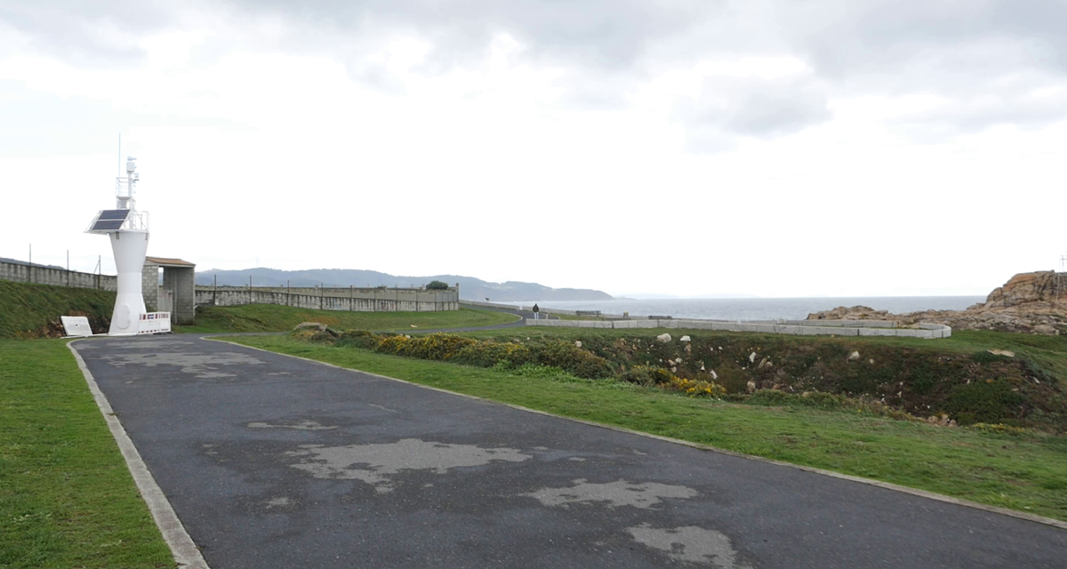
Figure 14.1 If the footage has shadows, they provide light angle, direction, and intensity. In this footage, though, the cloudy sky makes light bounce everywhere, and shadows nearly disappear.
Creating and Testing Lights
When you know about the lights and shadows in the real footage, you can start creating lights in your 3D scene to match that lighting. Again, the light settings may differ between EEVEE and Cycles, but for now, you’ll just set up the common basics; later, you’ll adjust the settings when you work in each render engine separately. Here, you’ll find a set of tasks you perform to create the scene lighting:
Background’s Alpha: When you click the Set As Background button in the Movie Clip Editor, Blender automatically loads the clip as the background for the camera. By default, its opacity is 50 percent. To see the lighting integration better, you should set the opacity to 100 percent. Select the camera. On the Properties Editor’s Camera Properties tab, you’ll find the Background panel. Inside this panel, you can select the video/images to use as the background for the camera and also adjust some of its settings. Set Alpha to 100 percent to increase the background’s opacity.
Floor: You need to create a plane for the floor to receive shadows. For now, create a plane, and adjust its size to fit the area Jim is walking on and to be wide enough to receive his shadows. You can take the road in the video as a reference to create this plane.
Rendered viewport shading mode: Whether you’re working in EEVEE or Cycles, before you start adding lights, you should enable Rendered viewport shading mode so that you can preview the resulting lighting and shadows created by the lights in your scene.
Sun light: If the real footage has defined shadows, you need a directional sun light that mimics the direction of the main light in the original scene. Just press Shift+A and create a sun lamp. Align the lamp, taking into account how the shadows are projected.
Next, adjust the softness of the shadows to fit the shadows in the footage. The footage you’re using here has no defined shadows, so you can use a sun coming from the top and increase the value for its angle, which will make the light and shadows softer. In Cycles, you should see the results right away; in EEVEE, you probably won’t, but don’t worry because you’ll adjust it later.
World light: If you have just the sun light, some parts of the character may be really dark because of the shadows. The world light can help fill those dark areas. By default, the world should have a neutral, subtle light.
You can find these settings on the World Properties tab of the Properties Editor. If you haven’t changed anything before, you should see a Background shader with a gray color and a strength of 1.0. If you change the strength value to 0.0, you’ll see how dark the scene is without the world lighting.
You can change the background color with a sky texture and play with it. You can also change its color to add a general light with a similar color to the real video’s sky. Then increase the strength value so that the world’s light fills the shadows on the character until the lighting matches the real video’s lighting as much as possible.
You can keep adjusting the sun light and world settings to make the integration match the video as accurately as you can.
Showing/Hiding Objects in Render
You may have objects that you don’t want to see in the scene (such as multiple heads with different facial expressions), and even though you clicked the eye icon in the Outliner to show or hide them, now that you can launch a final render, they show up in the rendered image.
The reason is that separate settings control the visibility of objects in the 3D Viewport and in the render. These separate settings come in very handy, given that you may have many objects that you don’t need to see while working, but you still want them to appear in the final render.
In the Outliner’s header is a funnel icon. Press MMB and drag the header left and right if the Outliner’s width is too small. If you press the funnel icon, you’ll see the Filters pop-over menu. At the top of that menu are the restriction toggles. When you enable those toggles, new icons appear next to the eye icon to the right of objects and collections in the Outliner.
You must enable the render visibility toggle, represented by a camera icon, which shows up next to the eye icon. Essentially, the eye icon controls the visibility in the 3D Viewport, and the camera icon controls the visibility in the final render.
Figure 14.2 shows the Filters menu and the icons next to datablocks in the Outliner.

Figure 14.2 The Outliner and the Filter menu within the Outliner. The Restriction Toggles in the Filter menu show or hide buttons that show up next to the objects in the Outliner. Those buttons let you control the object’s visibility in the 3D Viewport and in the render, for example.
Just find the objects you want to hide in the Outliner (or an entire collection, if you moved those objects into one), and disable the camera icon to hide those objects during the render.
Testing EEVEE and Cycles
Up until now, the settings are common to EEVEE and Cycles. To make sure everything is working, you can switch the render engine in the Render Properties tab of the Properties Editor.
My recommendation is that you work mainly with EEVEE to get fast feedback when you’re setting things up and switch to Cycles (which is generally slower) to test how things work.
To see what’s going on, remember to do this entire process in Rendered viewport shading mode in the 3D Viewport.
After learning the basics of working with nodes, you’ll start finishing the scenes in each render engine separately to adjust the appropriate settings.
Using the Node Editor
Before you dive into setting the scenes in EEVEE and Cycles to integrate the 3D models into the real footage, it’s important to learn the basics of nodes. In this section, I briefly show you how to use the Node Editor, and discuss what nodes are and how they work. After this introduction, you’ll be ready to carry on with some basic compositing.
Compositing
Usually, a scene doesn’t come out as you need it in the raw render, so you need to process it to make it look as good as possible. Sometimes, you need to render different elements on different layers and then compose them together in the compositing stage. Maybe you just want to place your 3D objects in a photo or real-world footage, so you need to mix those images with your render and adjust colors to make them match together. You can do such things in 2D image-editing software, such as Adobe Photoshop or GIMP, but you can use Blender compositing nodes for the same purpose.
You have two main ways to do compositing:
Do the compositing before the rendering. You take a test render, composite it in the Node Editor, and then launch the final render (even an animation) with the effects of the compositor applied. For this purpose, you use the scene render as an input.
Do the raw render of elements and then load those image sequences or videos into the compositor to integrate them. Suppose that you want to color-correct a video. Just load the video into the compositor, color-correct it, and render it. You don’t need to touch the 3D Viewport and definitely don’t need to render a scene again for such small retouches.
Understanding Nodes
When you take a simple render (a raw render, with no compositing involved), your scene is the input, and the output is the same as the input. When you enable the use of nodes, the input and the output are connected, but you can add nodes between them that apply effects and changes over the input before it reaches the output, thereby modifying the final result. The modifications can be as simple as making color corrections or as complex as adding visual effects or mixing renders.
The structure created with nodes is referred to as a node tree, and it gets its name because it has one end but many branches can come out of it. (In fact, the different groups of nodes that are mixed to achieve the final result are called branches.) You can also think of nodes as rivers; many small rivers converge, getting bigger and bigger, until they create the final river that gets to the ocean. The small rivers coming from the mountains are the inputs, and the output is the big river arriving at the ocean.
Figure 14.3 shows how a basic node tree can evolve as you add nodes.
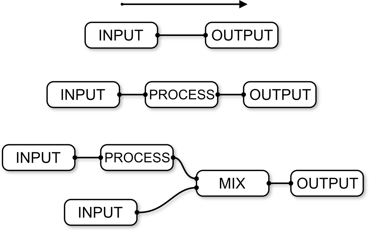
Figure 14.3 Three node trees, which could be the same in different stages of their evolution: a basic setup, which you get when you enable node editing (top); a modification added to the input before it reaches the output (middle); and a second input mixed into the result (bottom).
A node tree is always processed from left to right. Although you will find many node categories in the Node Editor, it may help to think about three main classes of nodes:
Input: These nodes introduce information to the node tree. An input node can be an image, a video, or a render from the 3D scene.
Process: These nodes take the information from the input nodes and modify that information. They can also mix information from different nodes to process them further in the node tree.
Output: These nodes collect the previously processed information and produce the final result, which can be saving the resulting image in your hard drive.
You can always add nodes between other nodes. Consider the third example in Figure 14.3. Each of the inputs might be a different render of a different layer of the scene. The first input has a process going on before it’s mixed with the second input; that process could be a color correction, for example. Suppose that you want to make your entire render look more reddish or have more contrast. You could add a color-correction node between the mix node and the output to affect all the previous nodes after the mix happens.
If you still don’t get how nodes work, you need to get your hands on them to understand their inner workings. As you continue this chapter and create your first node tree, you see the result with your own eyes and understand how your changes affect the result.
Studying the Anatomy of a Node
Before you start using the Node Editor, you need to know the parts that make up a node. Figure 14.4 dissects an RGB Curves node, which you use to make color corrections in the nodes you connect to its input. (I changed the colors of the Node Editor in User Preferences to improve readability, so yours will look different.)

Figure 14.4 The main parts of a node: connections, input sockets, properties, and output sockets
Sockets: Sockets are the little colored dots on the left and right sides of a node. They support the connections between nodes. The ones on the left are input sockets, and the ones on the right are output sockets. The color tells you what each connector is for. Gray is for values (or grayscale images); yellow is for RGB (red, green, blue) images and colors; and blue is for vectors (three values: X, Y, and Z). A given type of output should always be connected to the same color input of the next node, and you can use some converter nodes to convert the output to a different type if you need to. Some types are converted automatically if you connect them. An RGB output converts to grayscale when it’s connected to a gray input, for example, and RGB values turn into XYZ values when you connect a yellow output to a blue one (and vice versa). Next to those sockets is text that tells you what that socket should receive (if it’s an input) or what it’s sending (if it’s an output).
Node properties: Each node has different properties and is used for different purposes. You find all the properties inside the node itself. These properties define what operations are done to the information received from the input sockets. In the case of the RGB Curves node, the properties control how the colors will be processed before they’re sent to the next node through the output socket.
Node connections: A node does nothing by itself. Every node needs other nodes to work, which is why nodes are connected. The way and order in which you connect nodes define the result.
In the previous section, I mentioned three main classes of nodes: input, process, and output. You can identify which of these classes a node belongs to depending on the sockets they have. Input nodes have only output sockets, as they generate or load information. Process nodes have both input sockets and output sockets, because they need to be fed information that they will modify and then send to the next node. Output nodes are the end of the line, so they have only input sockets.
Using the Node Editor
In this section, you learn the basic controls of the Node Editor, as well as how to create and interact with nodes, connect them, and so on. Figure 14.5 shows the Node Editor.
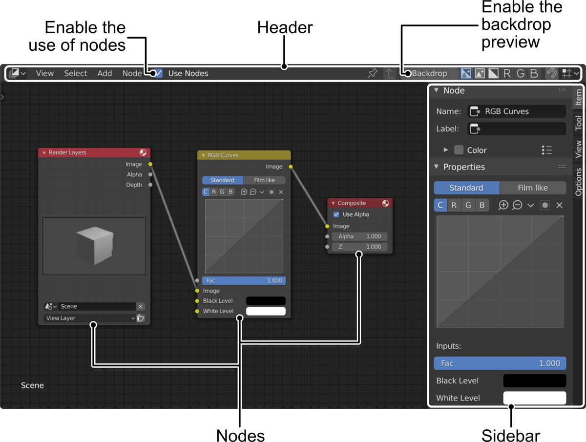
Figure 14.5 The Compositing Editor, one of the editors that use nodes
Getting Started with Nodes
You can use nodes for different purposes in Blender. If you check the list of editors, you’ll see several editors that use nodes, such as the Shader Editor, the Compositor, and the Texture Node Editor. Although the way they’re used is similar, as they all work with nodes, the nodes themselves vary.
In the Shader Editor, for example, the nodes are meant to create materials and load textures, whereas in the Compositor, you use nodes to mix layers and add effects to the scene’s final render.
When you enter the Compositor, you still don’t see anything. Before you start using nodes, you need to enable them in your scene. Enable the Use Nodes option on the Compositor’s header, and Blender displays basic node setup: the render (a Render Layers node) plugged into a Composite node (the render output). Nothing interesting is going on right now; the render goes out of Blender the same way it’s generated.
The Compositor is ready for you to start playing with nodes. If you launch a render now, it uses the node tree you have in the editor. If you need to launch a raw render without using the nodes, disable the Use Nodes option on the Compositor’s header.
Navigation is pretty straightforward, as it uses Blender’s standard controls. Press MMB to pan, and use the scroll wheel or press Ctrl+MMB to zoom in and out. General shortcuts for other editors also apply, such as pressing NumPad . to focus the view in the selected node or pressing Home to zoom out and show the entire node tree.
Creating Nodes
You have three ways to create nodes in the Node Editor:
Add menu: On the Compositor’s header, choose the type of node you want from the Add menu. Left-click the node to create it, move the mouse to the desired position where you want the node, and left-click again to place the node there.
Shift+A: If you press Shift+A inside the Node Editor, the Add menu appears at the mouse cursor’s position. Click the node type you want, drag it with your mouse, and left-click to drop the node in that place.
Using either of these methods, before you left-click to place the node in the editor, you can cancel by pressing Escape or RMB.
Connecting and Manipulating Nodes
The core of working with nodes is connecting them to make them interact. It’s also important to know how to move nodes so that your node tree is always organized. Otherwise, you can end up with a lot of overlapping nodes, which makes your work harder, as it becomes difficult to find specific nodes and understand their purposes. Here are some common controls that you use to manipulate nodes in any of the editors that use nodes:
You can select nodes by pressing LMB. Drag nodes by left-clicking and dragging.
Right-click to show the node’s contextual menu.
If you select several nodes by pressing B (box selection) or Shift+LMB, you can move them, rotate them, and scale them by pressing G, R, and S.
Left-click and drag in an empty space to perform a box selection (also done by pressing B).
To connect nodes, left-click and drag from an output socket of a node to the desired input noodle of another node.
If a node has multiple input sockets, and you want to switch a connection among them, left-click and drag from one socket to the other.
To remove a connection, left-click the input socket and drag the line connection to an empty space.
To remove one or more connections quickly, press Ctrl+RMB and draw a line over the connections you want to cut. When you release RMB, Blender removes the connections under the cutting line.
Select one or more nodes and press M to mute them. This method is a nice way to see in the preview how a node changes the image. Nodes become grayed out with a red line through them (if they have connections on both sides). Press M again to enable the muted nodes again.
You can duplicate nodes or groups of connected nodes by pressing Shift+D. You can also copy and paste nodes with Ctrl+C and Ctrl+V.
You can press H when you select a node to collapse it if you don’t need to access its properties so that it takes less space. Press H again to expand the node. Press Ctrl+H to hide unused sockets; this method is useful for nodes with many sockets to make the node tree less confusing. Press Ctrl+H to show those hidden sockets again.
Detach a node and leave the connection between the previous and next nodes intact by holding down Alt while dragging the node.
Select one or more nodes, and press X to remove them. Press Ctrl+X to delete them while keeping the connections between the previous and next nodes. As always, remember that Ctrl+Z lets you undo the latest actions if you make a mistake. Press Shift+Ctrl+Z to redo the last undo.
You can do many more things when working with nodes. I recommend that you take a look at the Node Editor’s menu, where you’ll learn about more options and keyboard shortcuts to execute them.
Previewing the Result
You don’t need to work blindly in the Compositor. You can have an image showing real-time updates of what you’re doing in the Compositor. To enable a preview, create a Viewer node from the Output nodes category. Add the node to your node tree, and connect the output of the node you want to preview to the input of the Viewer node.
An even faster method is to press Shift+Ctrl and left-click the node you want to preview. This method automatically creates a Viewer node and connects it to a specific node. Pressing Shift+Ctrl+LMB on any other node connects that node to the Viewer node so that you can switch the point of the node tree you want to preview really fast.
The Viewer node displays a preview of the node that is connected as an input.
When you have a Viewer node in your node tree, you have two options for previewing your work in the compositor:
Compositor Backdrop: In the Compositor, enable the Backdrop option on the editor’s header. Blender shows the resulting image behind your node tree, in the background of the Node Editor Workspace. Press Alt+MMB to pan, V to zoom out, and Alt+V to zoom in. Alternatively, you can drag the backdrop’s gizmo controls in the corners and center to move and scale the image.
Image Editor: Although the backdrop allows you to see everything in the same window, it can be very distracting at times, and the nodes on top of the image don’t always let you see what’s going on (especially in a complex tree). In such a case, or if you want to see the result on a secondary monitor, you have a nice way to preview your work. Open Image Editor, and select the Viewer Node output from the images list on the header. You see the Viewer node preview as though it were an image in the Image Editor.
Now any changes that you perform in the node tree will change the result in that preview, whichever preview method you’ve chosen. (You can also use both simultaneously.)
Rendering and Compositing Your Scene in Cycles
Compositing in EEVEE and Cycles is quite different. The options for compositing in Cycles are better equipped for compositing than those in EEVEE, generally. An action such as creating an object that renders only the shadows it gets from other objects requires just one click in Cycles but a more complex setup in EEVEE. Each render engine has limitations.
Blender has many compositing options, such as View Layers, which allows you to separate the objects in the scene in layers, so that you’ll have more control while compositing and adding effects. In this chapter, however, you’ll perform very basic compositing to integrate your walking character into the real footage, but be aware that the possibilities go much further.
Before you jump in, make sure that you have Cycles selected as your render engine. You can do so on the Render Properties tab in the Properties Editor; choose the render engine you want to use from the Render Engine drop-down menu.
It’s important to start with Cycles, as some of the parts are the same for EEVEE. After compositing with Cycles, you’ll learn the differences that make the scene work in EEVEE, and end up with a scene that you can render in both render engines and get similar results.
In both render engines, you need to capture the shadows of the scene’s floor so that Jim seems to be walking on the ground of the real video, starting by creating a shadow catcher in Cycles.
Creating a Shadow Catcher
A shadow catcher is an object that exists in the scene, but in the render, you see only the shadows that other objects cast on it. You can turn any object into a shadow catcher; then that object becomes transparent, receiving shadows only from other objects. You can create a plane for the floor and set it as a shadow catcher, for example. It will be transparent (letting you see the real video’s floor behind) but receive shadows from other objects in the scene, making it look as though the shadows were projected onto the real floor in the video.
In Cycles, creating a shadow catcher is very easy. To turn the floor plane into a shadow catcher, follow these steps:
Select the floor plane.
On the Object Properties tab of the Properties Editor, look for the Visibility panel and enable the Shadow Catcher option. If you’re in Rendered viewport shading mode in the 3D Viewport, you should see how the plane becomes transparent, but the shadows under Jim’s feet are visible on top of the background. If you set up the camera background to show the real video in Chapter 13, “Camera Tracking in Blender,” you have a pretty good view of the integration between the 3D character and the real video.
Make some more adjustments. You might change the color of the floor plane material so that it better resembles the color of the real video’s floor, for example. In Cycles, light bounces, so the color of the floor will influence the light Jim receives from the sun light after it bounces on the floor.
Finally, now that you can see the integration, you can adjust the parameters of the sun light and the world lighting to make them match the real video’s lighting as accurately as possible.
Now you have Jim’s shadows in place. The next step is setting up the final render so you can do the compositing.
Rendering in Cycles
In this section, you’ll see some of the settings that you may want to tweak so that Jim is rendered properly before compositing. Most of these options are on the Render Properties tab of the Properties Editor.
First, you need to adjust the samples. Remember that the more samples, the better quality and less noise in the render. In Render Properties, look for the Samples panel, and increase the samples number. There is no magical number; depending on your scene, the lighting, the complexity, materials used, and so on, more or less samples will be needed.
I recommend that you increase bit by bit and check the results to see when they’re good enough. In my case, I used 300 samples for the render. You can change the samples in the 3D Viewport while in Rendered viewport shading mode to see how many samples do a good job and then add that number to the render samples. In general, it’s better to have a low sample number in the 3D Viewport to work faster.
The more samples, the better the quality, but also the longer the render time.
You can enable Motion Blur. On the Render Properties tab is a panel called Motion Blur that creates a blur in fast-moving parts of the 3D scene. You can adjust the amount of the effect with the shutter slider inside the Motion Blur panel. You can see the motion blur effect only when launching the render (which you can do by pressing F12); it won’t be visible in the 3D Viewport.
The real video will most likely have some motion blur when the camera moves fast, so adding this effect to the 3D objects as well will improve the integration result.
You need to make the background of the world transparent so that while compositing, you can add the real video behind Jim and the floor shadows. If you launch a render right now, the background will have the world’s colors.
Fixing this problem is very simple. On the Film panel in the Render Properties tab of the Properties Editor, enable the Transparent option. If you launch a render now, you should see Jim over a background full of dark squares; those squares represent that those parts of the render are transparent.
Why doesn’t the background appear in the render too? Well, you can have different backgrounds for different viewports in the same scene; also, backgrounds in viewports are meant as references only. In the render, you have to add the background in other ways. One of those ways would be to load the real video in the world background that will be rendered. You’ll use the compositing method, in which you load the background behind the character after you render.
Finally, on the Output Properties tab of the Properties Editor, make sure that the dimensions are set to the size of the full HD real video: 1920px in X and 1080px in Y.
You need a render to start compositing, so you can press F12 in anticipation of that last stage of the process. The result should look similar to Figure 14.6.
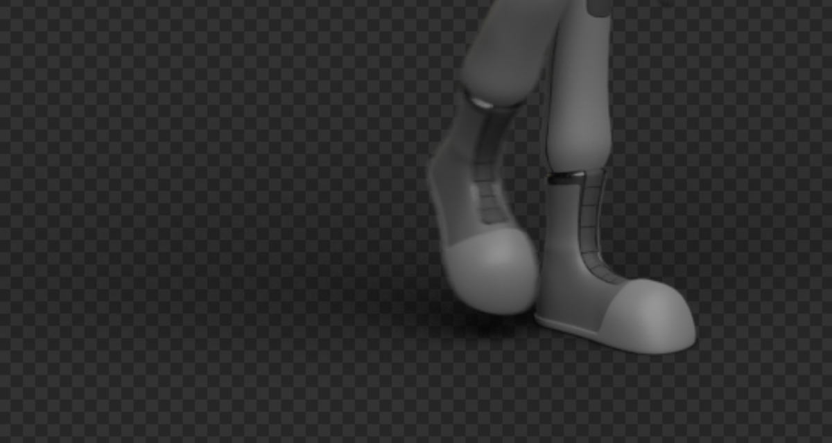
Figure 14.6 The render result so far. The background is filled with a pattern, indicating that the background is transparent, and the shadow is visible under Jim.
Node Compositing in Cycles
Let’s start the compositing! After you launch the render (by pressing F12 or from the Render menu), you’re ready to start. You can open a Compositor editor in any area or switch to the Compositing Workspace (with the tabs at the very top of the interface). Here are the steps to follow to integrate the real video with the 3D render by using compositing nodes. You see the node tree in Figure 14.7.
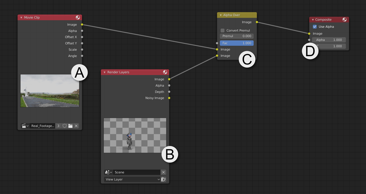
Figure 14.7 The compositing node tree for mixing Jim with the real video
Turn on the Use Nodes option in the Compositing node editor (on the Node Editor’s header).
You should see two nodes: Render Layers (B) and Composite (D). Render Layers inputs the render in the compositor. Composite is the output of the compositing and always the last node in the tree. You can enable the backdrop from the header. Press Ctrl+Shift+LMB on the Render Layers node to show its result in the background of the Node Editor. After that, press Ctrl+Shift+LMB on any node that has output sockets to connect it to the viewer node (which controls what is displayed in the background preview).
You need to load the video clip for the background. Press Shift+A, and from the Input category, select a Movie Clip node (A). If the clip isn’t selected already, choose it from the list at the bottom of the node. Keep in mind that this node loads a movie clip as long as it has been loaded into the Movie Clip Editor. In this case, you loaded the video in the Movie Clip Editor to perform the camera tracking, so it should be in the list of clips in the Movie Clip node.
Next, you need to mix the contents of the Movie Clip node and the Render Layers node. Typically, you could use a Mix node (Color nodes category) for this purpose, but because the Render Layers node is a render with alpha (transparency in the background), an Alpha Over node (C) will work better. Press Shift+A, and inside the Color nodes category, select Alpha Over.
The Alpha Over node essentially accepts two RGB (color or image) inputs and mixes them. You will find three input sockets: one for a factor (Alpha) and two for images. The first image input socket will be the background, and the second input socket will be shown on top of the first, respecting the alpha.
Connect the Image output from the Movie Clip node (A) to the first Image input in the Alpha Over node (C) and the Image output from the Render Layers node (B) to the second Image input of the Alpha Over node (C).
To preview what the Alpha Over node is doing, press Ctrl+Shift+LMB to connect it to the Viewer node, and display its contents in the Node Editor’s backdrop. You should see Jim and his shadows on top of the real video.
To finish, connect the output of the Alpha Over node (C) to the Image input in the Composite node (D). This step makes the result produced by the Alpha Over node the final output of the composited render.
Very basic compositing is done. If you press F12 to render now, Blender will know that you have compositing nodes in the scene, and it will do what the nodes order: first load the video and render the scene, then mix them together, and finally show the composited result (whatever comes into the Composite node). In Figure 14.8, you can see the resulting render.
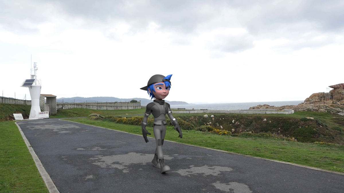
Figure 14.8 Final Render in Cycles
You could complicate and improve the result by adding other nodes in between this basic structure. You could add RGB Curves nodes between the Movie Clip and Alpha Over nodes to tweak the colors of the background before it’s mixed with Jim’s render, for example. The possibilities are endless. You could end up with hundreds of nodes to add effects and achieve whatever result you desire.
Rendering and Compositing Your Scene with EEVEE
In EEVEE, the process differs a bit from that of Cycles, but some parts are the same. The tricky part is that there is no Shadow Catcher option in EEVEE.
Switch the render engine to EEVEE from the Render Properties tab of the Properties Editor to start the process, and launch a render. Even though you set the floor plane as a shadow catcher in Cycles, the plane is still visible in the EEVEE render.
Creating a Shadow Catcher in EEVEE
In Cycles, the Shadow Catcher option exists because Cycles is a path tracer, and it can differentiate between different types of light rays, which makes it possible to isolate rays that are projecting shadows. In EEVEE, however, that’s not a possibility.
An alternative way to get a similar result to a shadow catcher relies on creating a material that turns a material and its shadows into a black-and-white image that you can use as an Alpha map for the floor. In Figure 14.9, you can see the node setup used for the floor material.

Figure 14.9 The node tree to create a shadow catcher material for the floor plane in EEVEE. There are two separate node trees in this material: one for the Cycles material (top) and a second one for the EEVEE material (bottom).
In Figure 14.9, the node tree for the floor material has two separate node trees. This is possible because you can have different outputs for Cycles and for EEVEE. Both render engines work differently, and some materials may produce different results, so Blender allows you to create two different node setups and show one or the other, depending on which render engine you’re using.
Follow these steps to create this node setup and make the floor work as a shadow catcher in EEVEE:
Select the floor, and open a Shader Editor.
If you created a material for the floor plane in Cycles to adjust its color, you should see a Principled BSDF node (A) connected to a Material Output node (B). If you didn’t, create a new material for the floor. Those same nodes should appear in the Node Editor.
This step is optional, but it may make working in the node editor more comfortable. Select the Principled shader (A) and press Ctrl+H to hide all the unused sockets so that the node takes less space. If you need to see all those sockets again, select the node and press Ctrl+H again.
In the Material Output node (B), choose All from the drop-down menu, and select Cycles. Now this material works only while you’re using Cycles as the render engine.
Now you’ll start building a separate node tree that works exclusively with EEVEE. Create a new Material Output node (G), press Shift+A, and select Material Output within the Output category. (You could also duplicate the previous Material Output node for the Cycles material by pressing Shift+D.) In this case, select EEVEE as the output render engine. The nodes that you’ll be creating from now on will be connected to this output.
Create a Diffuse node (C), pressing Shift+A and selecting it within the Shader category. Set its color to be white. This material is a white material that gets shadows from Jim, creating a grayscale result between the surface and the shadows.
Create a Shader to RGB node (D), pressing Shift+A and selecting it from the Converter category. Connect the Diffuse node (C) output with the Shader input in the Shader to RGB node (D). This node turns the shader connected to it into an RGB image, allowing you to use that result as though it were an image or texture instead of a shader.
Now you have a white material with shadows, and you’re turning it into an image. This image is white, with dark shadows. You need the opposite to be able to use this image as an alpha for the new material.
When you’re working with alphas, white represents opaque areas, and black represents transparent areas. That’s why you need to create an Invert node (E) that will take the Color output generated with the Shader to RGB node (D) and invert the colors. You can create an Invert node by pressing Shift+A and selecting it within the Color node category.
Almost done! You have the Alpha texture that will make the shadows opaque and the rest of the surface transparent ready. You need a shader to use it with.
Create a new Principled BSDF (F), pressing Shift+A and selecting it from within the Shader category. Now connect the output from the Invert node (E) to the Alpha input socket in the Principled Shader (F). Choose a dark color for the Principled Shader (F) so that the opaque areas, which represent the shadows, are dark.
Connect the Principled BSDF (F) output to the Material Output node (G). You won’t see it working yet because the material is not set up to allow the visualization of transparency effects. Go to the Material Properties tab of the Properties Editor, find the Blend Mode option in the Settings panel, and choose Alpha Blend to enable the material’s transparency effects.
By now, if you have the 3D Viewport in Rendered viewport shading mode, you should see the result.
Here’s a summary of what the nodes you’ve just created do:
The Diffuse node (C) is a white shader that gets the shadows from the scene’s objects.
The Shader to RGB node (D) turns the Diffuse node’s result into an image texture.
The Invert node (E) takes the image created by the Shader to RGB node (D) and inverts its colors, creating an image that is all black, in which the shadows are white—just what’s needed for a transparency map in which the shadows are opaque.
The Principled BSDF node (F) takes the image created by the Invert node and uses it as its Alpha, making the parts with shadows opaque and the rest of the surface transparent.
The Material Output node (G) gets the result from the Principled BSDF node (F) and turns it into the final material result. This result is shown only when you’re using EEVEE.
As you can see, creating a shadow catcher in EEVEE can be more tricky than just enabling a check box in Cycles. You could potentially add more nodes in the mix to adjust the result, change the shadow colors, or change their intensity. That’s the power of using nodes.
Rendering in EEVEE
You have to make some adjustments to ensure a good result with EEVEE. You may have made some of these changes during render tests of Jim’s shading in previous chapters. If not specified otherwise, you’ll find these settings on the Render Properties tab of the Properties Editor:
In the Sampling settings, you can increase the samples in both the render and the 3D Viewport. More samples will give you better-quality results, especially in shadows, because they are soft and require more calculations to look soft. 120 samples should be fine.
Enable Ambient Occlusion and adjust the settings to your liking. You can reduce the factor if the effect is too strong for the scene.
Enable Screen Space Reflections so that the reflective objects get reflections from objects around them, not only from the lighting and environment.
In the Shadows panel, increase the resolution, especially that of the Cascade Size, to improve how accurate the shadows are. Also, make sure that you enable the Soft Shadows option; otherwise, regardless of the light-angle settings, shadows will be hard.
In the Film panel, enable the Transparent option. This option is equivalent to the Film option in Cycles, making the background of the scene transparent.
When all these settings are in place, you should be ready to jump to the compositing stage.
Compositing in EEVEE
This stage will be very quick because you’ve already done it! Generally, you’d have to follow the same compositing process for EEVEE as you did for Cycles, but given that both engines are very compatible, Cycles compositing should be working in EEVEE as well. If you press F12 now, the render should launch and the compositing you did for Cycles should give you similar results in EEVEE.
The Render Layers node renders the scene, and with the other nodes, the scene’s render is overlaid on the real video clip. Render Layers renders whatever you have in the scene with the render engine that you have selected for that moment. Right now, the scene is set up in a way that it renders Jim with shadows on a transparent floor in both Cycles and EEVEE, so the compositing is the same as the one for Cycles.
In Figure 14.10, you can see the resulting render in EEVEE with the compositing already applied.

Figure 14.10 Final render in EEVEE
Exporting the Final Render
Whether you do it with Cycles or EEVEE, you need to learn how to export the final composited result with images and animations. For a single image, this step isn’t too important, as you can save the image from the Image Editor when the render is done by pressing Shift+Alt+S or choosing the option from the Image menu on the editor’s header.
In animations, though, when a frame finishes being rendered, Blender deletes it from temporary memory to start rendering the next one, so saving the rendered frames requires you to define beforehand where they should be saved.
Setting the Animation Output
In the Output panel on the Output tab of the Properties Editor, select the format you want to export the images in and the output folder where you want renders to be saved. For the format, I recommend PNG; the quality is better than JPG and not as good as TGA or TIFF, but the output takes up less space on your hard drive.
Launching the Final Render
You have only one thing left to do: Launch the render! Select Render Image or Render Animation from the Render button on the main menu at the top of the interface.
If you’re becoming a pro with Blender, use the keyboard shortcuts: F12 for a still-frame render and Ctrl+F12 to render the entire animation. Figure 14.11 shows the results in Blender Render and Cycles. As you see, there are only subtle differences between Cycles and EEVEE in a basic scene that doesn’t require advanced effects.
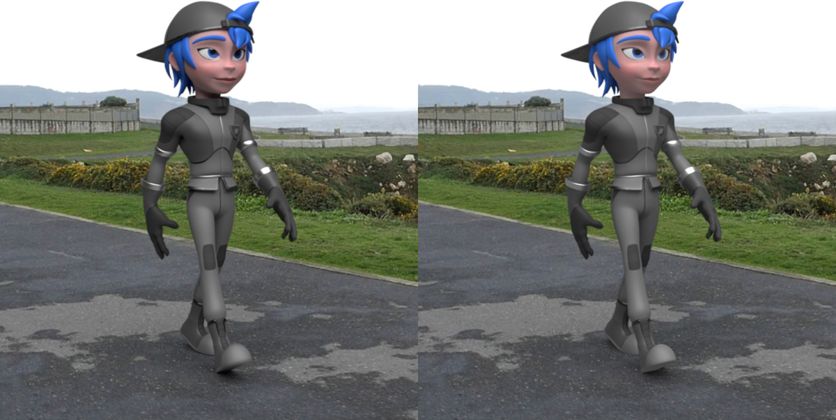
Figure 14.11 The final results with Jim integrated into the real footage in Cycles (left) and EEVEE (right)
Summary
Compositing is technical but also leaves room for you to be very creative. I hope that now you understand the basics, know how nodes work, and know why compositing has such a big effect on the final result.
You’ve come a really long way to get here, and you’ve completed this sample project. Congratulations! As you can see, integrating an animated character into a real video takes a lot of work and involves a lot of different skills: modeling, texturing, rigging, shading, animation, camera tracking, compositing, and so on. But all these skills can be really fun to use and learn, and they open up a lot of possibilities.
Now that you’ve gotten your feet wet, I encourage you to keep looking into the parts of the process you liked most. The goal of this book is to show you the entire process without digging too much into the details so that you can decide which areas to dedicate more time to. You may want to specialize in some areas, or you may like the entire process and want to become a generalist.
Exercises
Why is compositing so important?
What objects are meant to render only the shadows they receive?
What are View Layers for?
What node would you use to merge images?
Which node of your tree should you connect to the Composite node?