In this chapter you will learn advanced NXT-G programming principles. This includes learning more about Action, Sensor, Flow, and Data blocks. You will also learn how to create your own custom blocks. You will learn how to transmit data between programming blocks using data wires. By the time you have completed this chapter, you will have the foundational programming knowledge required to begin developing the NXT-G programs for the robots that you will learn how to build in Chapters 9 through 11.
The major topics covered in this chapter include:
Learning how to work with data hubs and data wires
Learning more about programming blocks that pass data through data wires
Learning how to create custom functions by building My Blocks
Tips for tracking program execution and locating and fixing errors
Passing Data Between Blocks Using Data Wires
Using the programming blocks and programming techniques discussed to this point in the book, you have the knowledge required to program simple robots that can move about and make sounds and display LCD text. However, to create robots that can perform specific tasks, interact with their environment, and adjust their operation, you need to learn how to work with data hubs and data wires, using them to pass data between programming blocks. This data can then be analyzed, incorporated into your NXT-G programs, and used to create vastly more complex NXT-G programs and thus more intelligent and capable robots.
With one exception, the Wait programming block, all NXT-G programming blocks are able to communicate and pass data among one another using data wires. Many programming blocks only work properly when you pass data to them through data wires.
A data hub is a projection that slides down from the bottom left of a programming block. Some programming blocks automatically display their data hub when added to a NXT-G program, but most blocks keep it hidden by default. To access a programming block’s data hub, click on the small tab indentation located at the bottom left edge of the programming block, as demonstrated in Figure 8.1. To hide a data hub, click on the tab located at the bottom of the programming block again.
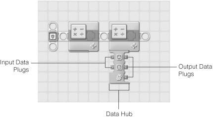
As shown in Figure 8.1, the data hub contains one or more data plugs. There are two types of data plugs, input and output. Input data plugs are located on the left side of the data hub and are used to accept data passed to the programming blocks. Output data plugs are located on the right side of the data hub and are used to pass data to other programming blocks.
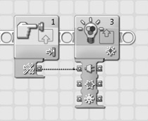
Data is passed between programming block data hubs by way of data wires. As demonstrated in Figure 8.2, a data wire is a connection between one block’s output data plug and another block’s input data plug. To draw a data wire from one block to another, move the mouse pointer over the output plug for the block that is to pass the data, making sure that you select the plug associated with the type of data you wish to pass. The mouse pointer will turn into a reel. Left click on the plug to begin drawing the data wire, drag the mouse pointer over to the appropriate input data plug on the other programming block and then release the mouse button.
Here, logic (True/False) data from a Touch sensor block is passed to a Display block. If a value of True is passed to the Display block, the Display block will clear the NXT Brick’s LCD screen. If a value of False is passed to the Display block, the LCD is not cleared.
Different blocks have different numbers of input and output plugs. If you look closely at Figure 8.2, you will notice that there are different graphic symbol labels displayed for each data plug. These symbols provide a visual description of the type of data that the plug is able to work with. In order to create valid connections between different programming blocks, the data wires that connect them must be connected to compatible data plugs. In the case of the example shown in Figure 8.2, the data wire is connected to data plugs that work with logic data on both blocks.
Trick
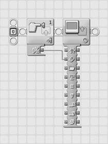
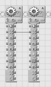
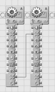
If you click on a data hubs tab after setting data connections, the data hub is automatically resized so that only the data plugs in use remain displayed as demonstrated in Figure 8.3.
The first two programming blocks show a data wire connected between two data plugs. The second two programming blocks show the same two data plugs after the data hub in the second block has been resized.
In order to create a valid data wire connection between two programming blocks, you must draw a data wire from one block’s output plug to the other block’s input plug. The two plugs must both support the same data type. Data types include numbers, text, and logic data. To assist you in identifying different types of connections, data wires are color coded, according to the following rules.
Green data wires pass logic data.
Yellow data wires pass numeric data.
Orange data wires pass text.
Every data plug is designed to collect and process a very specific type of data. For example, the Display block shown in Figure 8.2 supports nine different types of input and output plugs. If you position the mouse pointer over the graphic symbol that labels each of these plugs, the plug type is displayed in a popup window.
You can look up detailed information for every plug supported by a programming block by examining that block in the Lego Mindstorms NXT 2.0 Help file. For example, Figure 8.4 shows the table that you will find for the Display block.
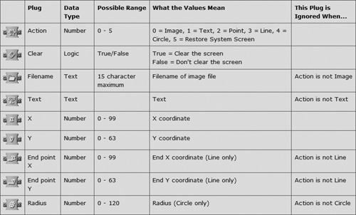
Using the information provided in this table, you can identify the type of data that a plug supports. In addition, you can identify the range of data that it supports as well as determine what the value of that data means. To set up a valid data wire, you must connect it between two data plugs that accept the same data type. However, to set up a useful data wire, you must also make sure that the plugs the wire will connect are an appropriate match for the data being passed. In the case of the Display block, this means that when sending X and Y coordinate data, you connect the data wires to the X and Y input data plugs and not to one of the other plugs that also happen to accept numeric data.
Trap
As demonstrated in Figure 8.4, some data plugs accept ranges of data. If data outside of these ranges is passed, an error will occur. The data passed may be ignored, or it may be changed to make it fit the range.
Sometimes data wires break. A broken data wire is one that is no longer valid. Broken data wires lose their color and turn gray, making them easy to identify. You cannot download NXT-G programs with broken wires into the NXT Brick. Data wires can break for three possible reasons, listed here:
Missing Input—. Occurs when you attach a data wire to an originating programming block that has no input source.
Too Many Inputs—. Occurs when an input plug is configured to receive data from more than one input plug. (Only one input plug is permitted per data wire connection.)
Data Type Mismatch—. Occurs when you attempt to connect a data wire between two incompatible data plug types (for example, an output plug that sends text to an input plug which needs numeric input).
An easy way to determine why a data wire has broken is to move the mouse pointer over the data wire and then look at the Little Help Window, which tells you which of the three types of errors has occurred. Figure 8.5 shows an example of a broken data wire that has missing input.
The data wire connection shown in Figure 8.5 begins at an output plug whose corresponding input plug does not have a data source. Figure 8.6 demonstrates that one way of fixing this error is to delete the data wire and redraw it, this time from the same type of data type plug, in this case, the one located at the bottom of the Move block’s data hub.
The broken data wire shown in Figure 8.7 has two input sources, which is not permissible.

Figure 8.8 shows an example of a broken data wire with a data type mismatch. Here a data logic output plug on a Touch sensor block has been connected to a Port input plug on a Color Lamp block. The logic plug passes a value of True/False, but the Port plug can only accept numeric data within a range of 1–4.
As data passes through an output plug and a data wire and then to another programming block’s input plug, the path that the data travels is referred to as the wire path. A wire path can be spread out through multiple programming blocks and data wires. This is achieved by connecting data wires through programming blocks, corresponding input and output data plugs as demonstrated in Figure 8.9.
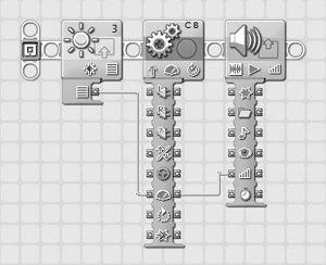
In Figure 8.9 the power level input and output plug is used to facilitate the creation of the wire path. Here, light intensity data is passed from a Light sensor to a Move block and then on to a Sound block where it is used to configure volume level. The data that traverses the wire path is not changed.
This book has already reviewed in great detail the programming blocks located on the Common palette. These are the same programming blocks that you will find in the Common group on the Complete palette. In addition, you will find instances of Common programming blocks located within other block groups on the Complete palette, where they also logically fit. This chapter reviews a number of the programming blocks found in the Action, Sensor, Flow, Data, and Advanced groups, with particular emphasis on how the blocks work with data wires.
The Actions group consists of five programming blocks. Of these, the Sound and Display blocks have already been covered in Chapter 7, “Working with the Common Programming Blocks.” These remaining three blocks are discussed in the sections that follow.
The Motor block is similar to the Move block. Both are designed to control servo motors. However, the Motor block provides more precise control. As shown in Figure 8.10, the Motor block displays information for four attributes: Port, Direction, Power, and Duration.

Trap
Avoid using both the Move block and Motor block in the same NXT-G program. Doing so increases the program’s size. Specifying one or the other allows for code sharing and means one less block has to be downloaded into the NXT Brick.
Figure 8.11 shows the Motor block’s attributes as seen in the configuration panel.
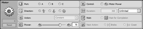
As shown in Figure 8.11, the Motor block supports a total of eight attributes and a Feedback box displays the number of degrees a servo motor has moved. These attributes include:
Specifies the servo motor’s power level.
Specifies whether Motor Power is set. If set, Motor Power causes the NXT Brick to attempt to supply whatever level of power is needed to ensure that the servo motor spins at its specified speed (for instance, when operating under adverse conditions).
Specifies whether servo motor movement should be measured in seconds, degrees, rotations, or unlimited.
Specifies whether the block should finish its execution before allowing other blocks on the sequence beam to execute.
The Send Message block, shown in Figure 8.12, is used to send messages wirelessly to another NXT Brick via Bluetooth. The Send Message block is designed to work in conjunction with the Receive Message sensor block on another robot. Wireless communications is an advanced topic not covered in this book. For more information, consult the Lego Mindstorms NXT 2.0 Help file.

The Color Lamp Block
The Color Lamp block, shown in Figure 8.13, is one of the simplest programming blocks to use. It controls the color sensor’s lamp functionality, enabling the display of red, green, or blue light. This block is usually used in pairs, one block turning a light on and the other block turning it off.

The Color Lamp block has the following attributes.
As shown in Figure 8.14, the Sensor group consists of nine programming blocks. Sensor blocks retrieve data from different sensors and send that data to other programming blocks that can analyze and act upon it. All sensor blocks pass data through sensor wires. All nine sensor blocks are operated in a similar manner, having only 2 or 3 attribute settings. This section will use the Touch sensor to demonstrate the operation of all the sensor blocks. To learn more about the other sensor blocks, consult the Lego Mindstorms NXT 2.0 Help file.
The Touch sensor block sends a logic value (True/False) through a data wire that indicates the current status of the Touch sensor. As shown in Figure 8.15, this block has just two attributes, both of which are displayed on its icon.
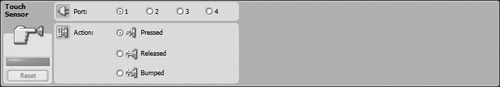
Specifies the type of action being tested: Pressed, Released, or Bumped.
To help demonstrate how this sensor block works, look at the example shown in Figure 8.16. Here, the Touch sensor block is used to control the direction in which a robot moves. The Touch sensor control block sends a logical value of True through its data wire when its sensor is pressed, and a False if it is not pressed. The value passed by the Touch sensor block is passed via data wire to the Motor block’s Direction input plug, which accepts logic data and sets the Motor block’s Direction attribute. If a True value is received, the Motor block sets the robot’s direction to forward. If a False value is received, the robot’s direction is set to backward.
As their name suggest, Flow programming blocks control the logical execution flow of programming blocks on NXT-G beams. There are a total of four Flow programming blocks. Three of these programming blocks, Wait, Loop, and Switch, are also found on the Common palette and have already been reviewed in depth in Chapter 7. The fourth block is the Stop block. It is arguably the easiest of all the programming blocks to work with. Its sole purpose is to halt a NXT-G program’s execution.
The Stop block, shown in Figure 8.17, has no configuration panel and thus has no attributes to configure. The Stop block has a single pair of data plugs, which receive and send logic data. When a value of True is received on its input plug, the block halts program execution. If a value of False is received, program execution continues unaffected.

Data programming blocks are designed to process data passed to them through data wires and to send output to other programming blocks through their output plugs. There are a total of seven different Data programming blocks, each of which is reviewed in the sections that follow.
The Logic Block
The Logic block, shown in Figure 8.18, performs a logical operation on two input values. The input values can be specified in the block’s configuration panel or supplied via data wire. The Logic block outputs a logical (True/False) value through its output plug.
As shown in Figure 8.19, the Logic block has a single attribute named Operation. In most cases, input values will be passed to the block via data wire. However, you can assign input values of True or False by selecting the check (True) or cross (False) for both of the block’s input values on the configuration panel.
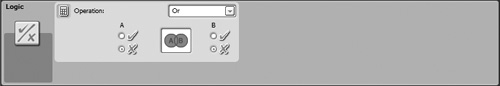
In addition, using the drop-down list located in the upper right corner of the configuration panel, you can select one of the four following logical operations that will be used to process the data values.
And. Outputs a value of True if both input values are true.
Or. Outputs a value of True if either or both input values are true (default).
Xor. Outputs a value of True if one input value is True and the other value is False. Outputs a value of False if both input values are True or both input values are False.
Not. Inverts a logical value (used when only one value is received as input).
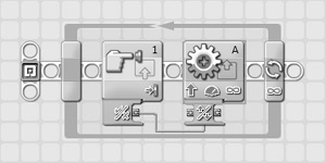
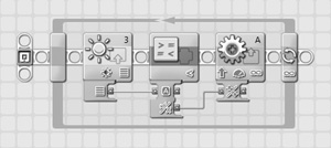
To help demonstrate how this data programming block works, look at the example shown in Figure 8.20. Here, logic data from the Sound and Light sensor blocks is passed to a Logic block where it is analyzed. If either of these sensor block’s logic data is True, a value of True is output by the Logic block. When received by the Move block, a value of True sets the robot’s direction to forward and a value of False sets the robot’s direction to backward.
The Math block, shown in Figure 8.21, performs a mathematical calculation using the two input values passed to the block, as indicated by the graphic symbol displayed on the block’s icon. The input values can be specified in the block’s configuration panel or supplied via data wire. The Math block outputs the two values as well as a number representing the result of the block’s calculation.
As shown in Figure 8.22, the Math block has a single attribute named Operation. In most cases, input values will be passed to the block via data wire. However, you can assign input values by typing values into the A and B entry fields.

Using the drop-down list located in the upper right corner of the configuration panel, you can select one of the six following mathematical operations that will be used to process the data values.
Addition. Adds the two numeric values together (default).
Subtraction. Subtracts the second value from the first value.
Multiplication. Multiplies the two numeric values.
Division. Divides the first numeric value by the second numeric value.
Absolute Value. Calculates the absolute value of a single value (used only when the block is given a single value to process).
Square Root. Calculates the square root of a single value (used only when the block is given a single value to process).
The Compare Block
The Compare block, shown in Figure 8.23, determines if one input is greater than, less than, or equal to another input, as indicated by the graphic symbol displayed on the block’s icon. The input values can be specified in the block’s configuration panel or supplied via data wire. The Compare block outputs the two values as well as a logical value representing the result of its comparison.
Figure 8.23. The Compare block determines if one input is greater than, less than, or equal to another input.
As shown in Figure 8.24, the Compare block has a single attribute named Operation. In most cases, input values will be passed to the block via data wire. However, you can assign input values in the form of two numbers by typing values into the A and B entry fields.
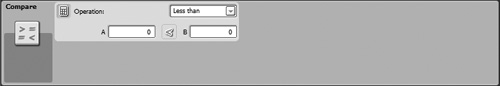
Using the drop-down list located in the upper right corner of the configuration panel, you can select one of the three following comparison operations that will be used to process the data values.
Less Than. Determines whether the first value is less than the second value (default).
Greater Than. Determines whether the first value is greater than the second value.
Equals. Determines whether the two values are equal.
To help demonstrate how this data programming block works, let’s look at the example shown in Figure 8.25. Here, logic data from the Light sensor block is passed to a Compare block where it is analyzed. If the Light Intensity value supplied by the Light sensor is less than 50, a value of True is sent to the Move block. Otherwise, a value of False is sent. When the Move block receives a value of True through the data wire, it sets the robot’s direction to forward. When a value of False is received, the robot’s direction is set to backward.
The Range block, shown in Figure 8.26, determines if a number is inside or outside of a range of numbers, as indicated by the graphic symbol displayed on the block’s icon. The input value can be specified in the block’s configuration panel or supplied via data wire. The Range block outputs the number as well as a logical value representing the result of its comparison.
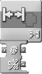
As shown in Figure 8.27, the Range block has two attributes: Operation and Test value. In most cases, an input value will be passed to the block via data wire.
However, you can assign an input value by typing it in the Test value entry field. The range against which the input value is compared can be supplied via data wires (not shown by default on the Range block), or they can be supplied by the Operation attribute. When configuring this attribute, you can choose between determining whether the input value is inside (default) or outside the range. To specify the range, you can either type its upper and lower values in the two entry fields or use the slider control to specify them.
The Random Block
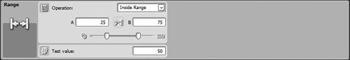
The Random block, shown in Figure 8.28, generates a random number within a specified range. The upper and lower ends of the range can be specified in the block’s configuration panel or supplied via data wire. The Range block outputs numbers representing the upper and lower range as well as its randomly generated number from within that range.

As shown in Figure 8.29, the Random block has a single attribute named Range. Minimum and Maximum range values can be passed to the block via data wire, or they can be specified as part of the Range attribute by typing them into the A and B entry fields. Alternatively, these values can be specified using the slider control located beneath the entry fields.
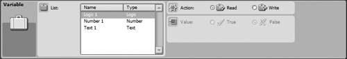
The Variable block, shown in Figure 8.30, retrieves or modifies a text, string, or logical value stored in computer memory. A variable is a value stored in the NXT Brick’s memory. Each Variable block displays the name of the variable that it is configured to work with. In addition, a graphic symbol displayed on the block indicates whether is has been configured to read a variable value from memory or write it to memory. As shown in Figure 8.30, the Variable block data hub displays an output plug when configured to read a variable. However, when configured to write to a variable, it displays both an input and an output plug, allowing the variable’s new value to be passed to the block via data wire.
Before a variable can be used in your NXT-G program, you must first define it. To define a variable, you must click on Edit > Define Variables. This displays the Edit Variables window shown in Figure 8.31. This window can also be used to delete variables.
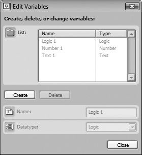
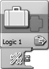
As shown in Figure 8.31, every variable that you define must be assigned a unique name and a data type. In addition, there are three default variables that are always available. These variables are named Logic 1, Number 1, and Text 1. To define a new variable, click on the Create button. Next, type a descriptive name for the variable in the Name field and then, using the drop-down list in the Datatype field, specify the variable’s data type. Click on Close when done.
It should be noted that variables exist only in the NXT Brick’s memory. When the NXT Brick is turned off, the variable is deleted from memory and you will have to define it again to use it.
Once defined, you can use the Variable block to assign a value to the variable and to retrieve that value. Figure 8.32 shows the configuration panel for the Variable block. Three attributes, described below, are available.
The Constant Block
The Constant block, shown in Figure 8.33, retrieves or modifies a text, string, or logical value stored in computer memory. A constant is a value stored in the NXT Brick’s memory that, unlike a variable, never changes. Each Constant block displays the name of the constant that it is configured to work with. The Constant block data hub has an output plug. A graphic symbol is displayed on the hub indicating the constant’s data type.

Before a constant can be used in your NXT-G programs, you must first define it. To define a constant, you must click on Edit > Define Constants. This displays the Edit Constants window shown in Figure 8.34. This window can also be used to edit and delete constants.
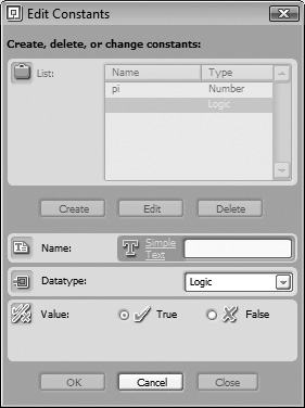
As shown in Figure 8.34, every constant that you define must be assigned a unique name and a data type. To define a new constant, click on the Create button and type a descriptive name for the constant in the Name field and then, using the drop-down list in the Datatype field, specify the variable’s data type (Logic, Number, or Text), and then specify the constant’s value in the Value section. Click on Close when done.
You can use the Constant block to retrieve the value assigned to the constant whenever you need it. Figure 8.35 shows the configuration panel for the Constant block. Four attributes, described below, are available.
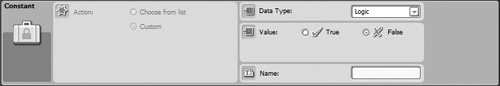
The Action attributes allow you to either choose the constant you want to work with from a list of existing constants or to use the block to define a new constant.
The Data Type attribute, available only when using the block to define a new constant, is used to specify either Logic, Number, or Text as the constant’s data type.
The Value attribute, available only when using the block to define a new constant, allows you to specify a value for the constant.
Advanced programming blocks represent programming blocks that do not fit into any previously discussed block groups. They perform a range of different functions. There are a total of seven Advanced programming blocks, each of which is reviewed in the sections that follow.
The Number to Text block, shown in Figure 8.36, converts a numeric value to a text value, allowing it to be displayed on the NXT Brick’s LCD. The input value can be specified in the block’s configuration panel or supplied via data wire. The Number to Text outputs two values, the number that needs to be converted and the text string version of that number.
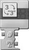
Figure 8.36. The Number to Text block converts a number to a text string allowing it to be displayed on the NXT Brick’s LCD.
As shown in Figure 8.37, the Number to Text block has a single attribute named Number. Normally, the number that the block converts into text is passed to it via data wire. Alternatively, you can specify the number to be converted by typing it into the Number entry field.

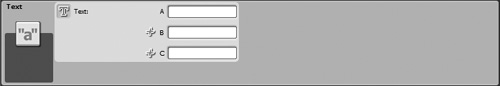
The Text block, shown in Figure 8.38, concatenates up to three strings together, creating a new longer string. The input values can be specified in the block’s configuration panel or supplied via data wire. The block outputs up to four values, the source text strings, and the resulting concatenated text string.
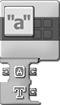
As shown in Figure 8.39, the Text block has a single attribute named Text. Normally, the text strings that the block concatenates together will be passed to it via data wire. However, you can specify the text strings by typing them into the three text fields labeled A, B, and C.
The Keep Alive block is used to override the NXT Brick’s automatic sleep mode, which puts the NXT Brick to sleep after a period of inactivity resulting from non-use. See Figure 8.40.

Unlike the other Advanced programming blocks, the Keep Alive block does not have any attributes to configure.
The File Access block writes or reads numeric or text data files on the NXT Brick. The File Access block works similarly to the Variable block, except that instead of storing data in memory, the data is stored in a file, allowing it to be stored indefinitely. On the down side, storing data in files consumes more of the NXT Brick’s available storage space.
As shown in Figure 8.41, graphics symbols that indicate the type of data being worked with are displayed on the File Access block. The symbols also indicate whether the block has been configured to read or write data.
Figure 8.42 shows the configuration panel for the File Access block. Its attributes are described below.
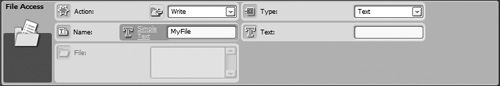
The Action attribute specifies the actions performed by the block. Available choices include:
Read—. Reads the data stored in the specified file.
Write—. Writes data to the specified file. If the target file already contains data, the new data is written to the end of the existing file.
Close—. Closes a file after it has been written to or read from.
Delete—. Deletes the file.
The Name attribute is used to specify the name of the data file that will be created, processed, deleted, or closed.
The File attribute is available only when your NXT Brick is connected to your computer. It allows you to select an existing file stored on your NXT Brick.
The Calibrate Block
The Calibrate block is used to calibrate the sound and light sensors. Its value is represented as a percentage between 0 and 100. As demonstrated in Figure 8.43, symbols displayed on the Calibrate block indentify whether it has been configured to work with the light or sound sensor as well as whether the block has been configured to set the minimum or maximum value.
Hint
In addition to calibrating sensors using the Calibrate block, you can also calibrate sensors from the Lego Mindstorms NXT 2.0 GUI, as described in Chapter 2, “Getting Started.”
Figure 8.44 shows the configuration panel for the Calibrate block. Its attributes are described below.
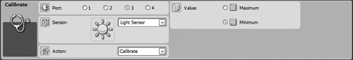
The Port attribute specifies the port on the NXT Brick to which the sensor being configured has been attached (1, 2, 3, or 4).
The Sensor attribute specifies whether the programming block is to be used to calibrate a light or sound sensor.
The Action attribute is used to specify whether the block will calibrate or delete the specified sensor. Deleting a sensor simply restores its default settings.
The Reset Motor block, shown in Figure 8.45, is used to reset the servo motor’s automatic error correction feature. Text displayed in the upper right corner of the Reset Motor block shows the ports on which the block will perform the reset. Although not shown by default, this block’s data hub has three input and output data plugs that can be used to receive and send the port assignments of the servo motors.

Figure 8.46 shows the configuration panel for the Reset Motor block. As you can see, it contains a single attribute named Port, which is used to specify on which port (A, B, or C) the reset action should take place.
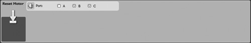
This programming block is seldom used. However, it can be helpful in situations where the Move or Motor blocks have been configured to set the servo motors to coast to a stop. In these situations the servo motor’s automatic error correction should accurately keep track of motor movement. However, if you need to, you can use the Reset Motor block to stop automatic correction.
The Bluetooth Connection block, shown in Figure 8.47 is used to establish a connection with another Bluetooth device, such as another NXT Brick. To learn more about this feature, consult the Lego Mindstorms NXT 2.0 Help file.

As you gain additional experience developing NXT-G programs for your robots, you may often find yourself repeatedly working with and configuring certain groups or programming blocks in the same way over and over again. This is not an efficient use of time or energy. A better solution is to develop a custom My Block made up of these programming blocks and then add the My Block to your NXT-G programs whenever you need to perform whatever task(s) those programming blocks are designed to manage. In this way, you can create a personal library of custom functions, each of which performs a specific task, allowing you to quickly assemble new NXT-G programs without having to continuously reinvent the wheel. My Blocks can also be used to hide complexity in your NXT-G programs.
My Blocks are stored and managed on the Custom palette. They exist in two forms: My Blocks and Web Blocks. A My Block is a collection of one or more customized programming blocks that perform a specific task. A Web Block is a My Block that someone else has developed and which you have downloaded from the Internet, allowing you to leverage someone’s programming knowledge and experience. Lego Mindstorms NXT 2.0 does not come with any My Blocks or Web Blocks.
My Blocks are nothing more than collections of programming blocks that you configure to perform a specific action and then save as a reusable unit in the form of a new programming block. Once created, My Blocks can be added to a NXT-G program just like any other programming block.
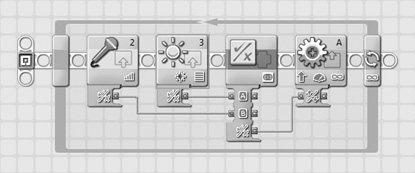
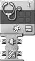
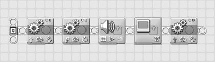
To create a My Block, add and configure the programming blocks you want to use to the work area. For example, you might create a My Block using the programming blocks shown in Figure 8.48.
Once you have finished configuring the programming blocks, select them and either click on the Create My Block toolbar button or click on Edit > Make A New My Block. In response, the My Block Builder window appears. Assign a descriptive name to the block by filling in the Block Name field and then document the block’s function and purpose in the Block Description text field as demonstrated in Figure 8.49.

Figure 8.49. The My Block Builder window displays the selected programming blocks and allows you to name and describe the My Block.
When done, click on Next and the My Block Builder window will help you create a custom icon for the My Block. The bottom part of the window displays a list of icons that you can drag to the Icon Builder entry field at the top of the window. You can resize the icon by clicking one of the four squares located at the four corners of the icon. A preview of how the My Block’s icon will look, located in the top right corner of the window, is immediately updated. You may drag and drop more than one icon onto the Icon Builder entry field, as demonstrated in Figure 8.50.
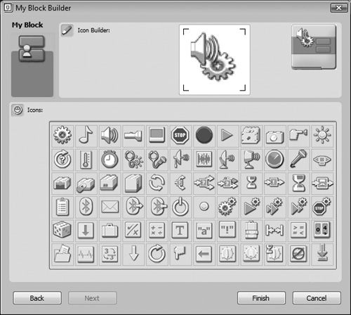
Figure 8.50. You can add and configure one or more icons to the Icon Builder entry area in order to configure the appearance of your My Block.
Once you are done configuring the appearance of your My Block, click on Finish.
The programming blocks that make up the My Block are then removed from the work area and replaced with the new My Block, as demonstrated in Figure 8.51.
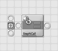
Figure 8.51. Once completed, the My Block is displayed in place of the programming blocks that comprise it.
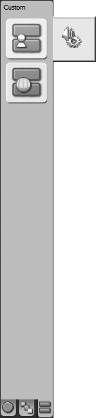
The My Block is automatically added to the Custom palette. To view it, simply move the mouse pointer over the My Block icon, as demonstrated in Figure 8.52.
If you decide you need to make a change to a My Block, you may do so by adding it to the work area and either double clicking it or selecting it and then clicking on Edit > Edit Selected My Block. In response, the contents of the My Block are displayed in their own tabbed window in the work area. Make any required changes to the programming blocks that make up the My Block and then close its tabbed window. Click on Yes when prompted to save your changes.
You can also modify a My Blocks icon by selecting it and then clicking on Edit > Edit My Block Icon. My Blocks are stored in their own folder as files with an .rbt file extension. You can delete a My Block by selecting it and then clicking on Edit > Manage Custom Palette. This will display a window containing two folders, one for your My Blocks and one for your Web Blocks. Open the My Blocks folder, select your My Block file and then press the Delete key to delete it.
If you want, you can take a copy of the My Block file and share it with others, from your Web site, for example. Any My Blocks that you share in this manner will be regarded as Web Blocks by others who download and add them to their Lego Mindstorms NXT 2.0 development environment. To share a My Block, add it to the work area and then click on Edit > Manage Custom Palette. Locate and open the My Blocks folder and then make a copy of My Block and you are ready to share it.
To delete a My Block, add it to the work area and then click on Edit > Manage Custom Palette. Locate and open the My Blocks folder, select the My Block, and press the Delete key. If you delete a My Block, you must then go back and modify any NXT-G programs that made use of it. Otherwise, those programs won’t work any more. Figure 8.53 shows an example of what a broken My Block looks like.

As has been stated, a Web Block is just a My Block that you have gotten from somebody else, downloading it from the Internet, for example. Once you have downloaded a Web Block from the Internet, all you have to do to begin working with it is to add it to your Lego Mindstorms NXT 2.0 working environment. To do so, click on Edit > Manage Custom Palette and open the Web Blocks folder that is displayed. Drag and drop your new Web Block(s) into this folder and close it.
The next time you place the mouse pointer over the Web Blocks group on the Custom palette, your new Web Blocks will be displayed, and you can begin working with them.
Beginning in Chapter 9, “Go Bot,” and going to the end of this book, you will begin developing robots and the NXT-G programs that make them work. As you do so, you may run into occasional problems. Most of the time, all you will have to do to locate and fix programs is carefully review your programming blocks and look for your mistake. Sometimes, however, mistakes are not easy to find. In these situations, you need to do a little debugging.
First and foremost, your NXT-G programs won’t download to your NXT Brick if they contain certain types of errors. These errors include:
Broken data wires
Broken data blocks
You will have to identify and fix both of these types of errors before you can download and test your NXT-G programs. In addition, sometimes programming blocks are accidentally removed from a NXT program’s sequence beams. Any program blocks not connected to sequence beams are not downloaded to the NXT Brick. Check your programs for disconnected programming blocks, and reconnect or remove them as appropriate.
Once you have downloaded your program to your NXT Brick, you can run, test, and debug them. Debugging is the process of locating and fixing errors that occur within computer programs. Unlike some programming languages, NXT-G does not have a built-in debugging tool. However, there are a few simple tricks that you can employ to help you when trying to locate where errors are occurring within your NXT-G programs. For starters, you can embed extra Sound blocks at strategic points within your programs and configure those blocks to play tones so that you know when different parts of your NXT-G programs are executing. Using this approach, you may be able to determine the part of your NXT-G program where an error is hidden, just by watching your robot run and listening for the tones that tell you when different parts of your NXT-G programs are executing.
In a similar fashion, you can embed extra Display blocks within your NXT-G programs when you are developing them and use those blocks to display relevant information when your NXT-G programs run. Information that is displayed might include data that is passed between blocks via data wires or messages that indicate variable values. You can also use Display blocks in place of Sound blocks to identify when different parts of your NXT-G programs execute.
Another way to determine what is going on as your robots run is to leave your robot’s NXT Bricks attached to your computer when it runs. This allows you to monitor feedback boxes belonging to programming blocks.
This chapter rounded out your NXT-G programming foundation by completing your review of NXT-G programming blocks, including those in the Action, Sensor, Flow, and Data groups. You learned how to transmit data through these programming blocks using data hubs and data wires. You also learned how to create custom functions that facilitate code reuse through the development of My Blocks. Lastly, you learned a few tricks for tracking programming execution and locating and fixing program errors. You are now ready to begin developing the NXT-G programs needed to automate the operation of the robots whose development is covered in Chapters 9 through 11.