
This chapter’s robotic project is Detector Bot. Detector Bot is a modified version of Tracker Bot. Its job is to seek out an object located at the end of its path. It features a new assembly that includes a touch sensor. This allows the robot to detect when it comes into contact with its target object. With this new sensor assembly in place, the robot will be able to finally reach the end of its quest, following its path until it finds its objective.
The major topics covered in this chapter include:
A review of the features and capabilities of Detector Bot
Detailed building instructions for Detector Bot
Instructions for developing the NXT-G program that operates Detector Bot
Detector Bot represents another evolutionary step in the development of the robot that you developed in Chapter 9, “Go Bot.” In this chapter, the robot is enhanced with a touch sensor, enabling it to detect when it comes into contact with another object. Along with this new capability comes a new job for Detector Bot: to follow its assigned path until it finds its target object, which can be a book, a shoe, or anything else you choose to place in the robot’s path.
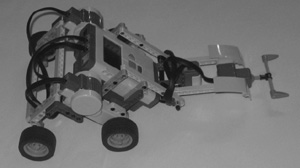
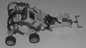
Figure 11.1 shows how Detector Bot will look when it is complete. Note the addition of the touch sensor located in the front of the robot as well as the use of a cross axle and two teeth that extend the ability of the touch sensor to detect objects along a wider path.
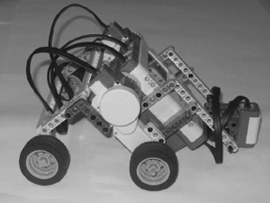
Tracker Bot, shown in Figure 11.2, is the starting point for the creation of Detector Bot. Detector Bot has a new touch sensor assembly that allows it to determine when it comes into contact with other objects.
Detector Bot will be created in six steps, as outlined here:
Preparing the touch sensor for connection
Connecting screens to the assembly
Adding support beams to the assembly
Extending touch sensor reach
Connecting the touch sensor assembly
Programming Detector Bot
Figure 11.3 provides a complete inventory of the parts needed to enhance Tracker Bot and turn it into Detector Bot. Begin your work on this project by retrieving these parts from your Lego Mindstorms NXT 2.0 kit.

Begin the development of Detector Bot by preparing the touch sensor for connection to the robot. This involves the connection of several connector pegs with friction 3M and a pair of 3M straight beams to the sensor.
Step 1: Place the touch sensor upside down and connect a connector peg with friction 3M to it, as shown in Figure 11.4.

Step 2: Attach two connector pegs with friction 3M to two 3M straight beams, as shown in Figure 11.5.

Step 3: Take the two 3M straight beams and connect them to the touch sensor using the already attached connector pegs with friction 3M, as shown in Figure 11.6.
Hint
Figure 11.7 shows how the touch sensor looks now that it has been prepared for connection to the sensor assembly.

To give Detector Bot a bit of an armored look and feel, let’s connect the left and right screens to the touch sensor, providing the sensor with a little added protection in the process. In addition to making the touch sensor assembly look a little snazzier, these screens also assist with the sensor’s connection to the robot and serve as key components to connect the sensor to its support beams.
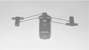
Step 1: Place the left and right screens upside down on a flat surface and connect a connector peg with friction and a connector peg with friction 3M to each screen, as shown in Figure 11.8.

Step 2: Place the touch sensor in an upright position between the two screens and connect the screens to the sensor, as shown in Figure 11.9.

Hint
Figure 11.10 shows how the touch sensor looks now that it has been connected to the left screen and the right screen.

In order to connect the touch sensor to the robot, you need to provide the assembly with a pair of support beams.
Step 1: Connect a pair of connector pegs with friction 3M to two 11M straight beams, as shown in Figure 11.11.

Step 2: Connect the support beams to the touch sensor assembly, as shown in Figure 11.12.

Hint
Figure 11.13 shows how the touch sensor assembly looks now that its support beams have been added.

The touch sensor is able to detect contact with another object only along a very small area (its orange tip). It is possible for the robot to come into contact with another object but for the touch sensor not to detect it unless the object is placed dead center in front of the robot. By adding a small attachment to the front of the touch sensor, you can significantly expand its reach.
Step 1: Insert a 9M cross axle into a catch with cross hole and then center the catch on the axle. Add a pair of teeth to the end of the 9M cross axle and connect a 3M cross axle to the open end of the catch with cross hole, as shown in Figure 11.14.

Step 2: Connect the component you assembled in the previous step to the touch sensor assembly, as shown in Figure 11.15.

Hint
Figure 11.16 shows how the touch sensor assembly looks now that it has been completely assembled.

Now that the touch sensor assembly has been fully assembled, it can be connected to the robot.
Step 1: Withdraw the two connector pegs with friction 3M from the end of both 11M straight beams and slide the beams between the robot’s color sensor and the support beams to which the color sensor is attached. Attach the end of the touch sensor assembly’s support beams to the robot, as shown in Figure 11.17 using the two connector pegs with friction 3M that you previously withdrew.

Hint
When properly attached, the touch sensor can be raised or lowered. When lowered, it should float approximately a quarter inch above the surface of the ground.
Step 2: Using a 20cm/8-inch cable, connect the touch sensor to Port 1 on the NXT Brick, as shown in Figure 11.18.
Now that you have completed the transformation of Tracker Bot into Detector Bot, it is time to update the robot’s NXT-G program, enabling it to capture and process touch sensor input. The NXT-G program enhancements include the expansion of the NXT-G program’s loop in order to incorporate the continuous collection and analysis of touch sensor input. Specifically, the program will be modified to accommodate the following actions:
Repeatedly collect and analyze touch sensor data.
Announce that an object has been detected and display a corresponding message on the NXT Brick’s LCD when the robot makes contact with another object.
Halt program and robot execution when contact is made with another object.
Play a Game Over message and display corresponding text if the robot does not make contact with another object within 60 seconds.
As with previous projects, Detector Bot’s NXT-G program will be developed in a series of stages. In the first stage, Tracker Bot’s program will be copied and renamed. In the second stage, the program’s programming logic will be updated to include the collection and analysis of touch sensor input and to halt program execution if appropriate. Once this stage is complete, you will put Detector Bot through its first test run to ensure that the program enhancements work correctly.
In the third stage of the NXT-G program’s development, you will add programming logic that announces the end of the program’s execution (when 60 seconds has expired without the robot detecting its target object). You will once again test the robot’s operation, this time to validate that the program shuts down the robot’s execution, as just described, when time expires. The fourth and final stage of the NXT-G program’s development enhances the program through the addition of comments.
Stage 1 of the development of the NXT-G program for Detector Bot is quite simple. Begin by making a copy of the Tracker_Bot program, renaming it Detect_Bot. Double click on the Detect_Bot program to open and load it into Lego Mindstorms NXT 2.0 GUI. Verify that it contains the programming logic outlined in Figure 11.19.
Stage 2 involves the incorporation of programming logic that captures and analyzes touch sensor data and manages early program termination when the robot detects contact with another object in its path.
Begin by dragging and dropping a Switch code block inside the program’s Loop block, placing it after the existing Switch block (which processes color sensor data). Select and configure the new Switch block as follows:
Control—. Select Sensor from the drop-down list.
Sensor—. Select Touch Sensor from the drop-down list.
Display—. Make sure the Flat View option is selected.
Port—. Select port 1.
Action—. Select Pressed as the action that will trigger the program blocks located in the upper half of the Switch block.
Next add a sound block to the upper half of the Switch block. This block will be used to play an audio file when the robot makes contact with another object. Select and configure the new Sound block as follows:
Action—. Select Sound File.
Control—. Select Play.
Volume—. Set value level to 100 percent.
Function—. Ensure that Repeat is not selected.
File—. Select Object Detected from the list of files in the scrolling list box.
Wait—. Select Wait for Completion.
A message should be displayed on the NXT Brick’s LCD announcing when an object has been detected. To do so, drag and drop a Display block onto the top half of the Switch block, placing it after the Sound block. Select the Display block and configure it as follows.
Action—. Select Text from the drop-down list.
Display—. Select Clear.
Text—. Type Object found in the text field entry box.
Position—. Specify a value of 8 for the X coordinate and 32 for the Y coordinate.
Drag and drop a Sensor Wait block at the end of the sequence beam. Select the Sensor block and configure it as follows:
Control—. Select Time from the drop-down list.
Until—. Type a value of 1 in the Seconds entry field.
Next, drag and drop a Stop block into the Switch block, placing it after the Display block. The Stop block has no configuration panel. Its purpose is to halt the execution of the NXT-G program.
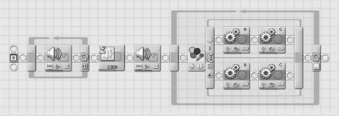
Figure 11.20 shows how the programming logic outlined in the program’s loop should look at this point in the NXT-G program’s development.
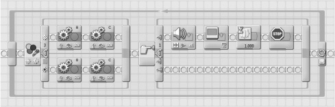
Figure 11.20. The programming logic in the NXT-G program’s loop has been enhanced to capture touch sensor data and to control early program termination.
Before continuing to the final stage of the NXT-G program’s development, set aside some time to test the robot and make sure it operates as previously described. Start by saving the program. Next, connect the robot (e.g., the NXT Brick) to your computer and download the program by clicking on the NXT Download button located at the bottom right corner of the work area. Disconnect Tracker Bot, place it on the Mindstorms NXT 2.0 Test Pad and press on the NXT Brick’s orange button four times to select and run the NXT-G program. Once you have verified that the robot has successfully located and begun tracking the path outlined by the solid block line, place an object like a book or soda can in Detector Bot’s path and make sure the robot detects the object and then halts.
If Detector Bot does not perform as expected, go back and review each of the programming blocks that you added to the new Switch block that you inserted inside the program Loop block and ensure that their configuration matches up with the configuration settings specified for each block. If you find any errors in block configuration, correct the errors and then download, and retest the robot again.
The last stage in the development of Detector Bot’s NXT-G program requires the addition of two programming blocks. These blocks will not materially affect the operation of the robot. Their purpose is to shut down the robot after 60 seconds of operation.
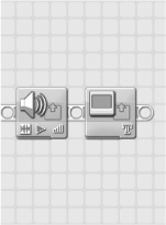
Begin by dragging and dropping a Sound block to the end of the sequence beam, just after the end of the program’s Loop block. Select the Sound block and configure it as follows.
Action—. Select Sound File.
Control—. Select Play.
Volume—. Set value level to 75 percent.
Function—. Ensure that Repeat is not selected.
File—. Select Game Over from the list of files in the scrolling list box.
Wait—. Select Wait for Completion.
Wrap things up by dragging and dropping a Display block onto the end of the sequence beam, placing it just after the Sound block that you just configured. Select the Display block and configure it as follows.
Action—. Select Text from the drop-down list.
Display—. Select Clear.
Text—. Type Object not found in the text field entry box.
Position—. Specify a value of 3 for the X coordinate and 28 for the Y coordinate.
At this point, you have completed the development of the NXT-G program’s programming logic. Figure 11.21 shows how the two programming blocks that you just added should look.
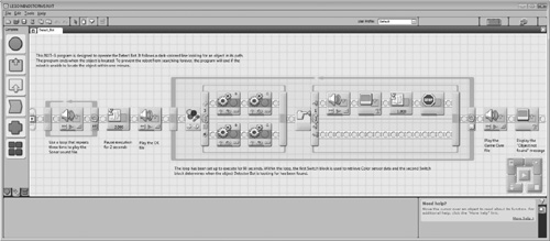
All that remains to wrap up your work on Detector Bot is to update the NXT program’s internal documentation through the addition of comments that explain the program’s purpose and operation. This is accomplished by adding the comments shown in Figure 11.22 to the program.
In this chapter you learned how to enhance Tracker Bot, turning it into Detector Bot through the addition of a new touch sensor assembly and the extension of its NXT-G program. Detector Bot sill locates and follows a dark line wherever it may go. However, the robot now has the ability to determine when it comes into contact with another object, allowing it to ascertain when it has found its target object and completed its mission.