In Chapter 3, “Working with Electronic Components,” you learned all about the NXT Brick and the electronic motors, sensors, and cables that are included as part of the Lego Mindstorms NXT 2.0 kit. These are important pieces, but they only represent 15 of the 619 pieces in the kit. A thorough understanding of the other pieces is essential to robotic development. In this chapter you will learn about all of these pieces, including how to identify them, their function, and their color and quantity.
The major topics covered in this chapter include:
Beams
Connectors
Gears
Other pieces
One of the challenges of working with the many pieces and parts provided in the Lego Mindstorms NXT 2.0 kit is that other than the NXT Brick and the electronic components, Lego has not assigned names to the other pieces. This can make identifying them challenging. As a result, different people refer to the same parts using different names. As you can imagine, this can lead to confusion. To facilitate part identification in this book, a number of different identification techniques will be applied to help simplify things. This will include using attributes like part length and color as well as categorizing parts into differently named categories and leveraging a few Lego terms.
One of the primary parts used in just about any robotic creation is the beam. Beams are used to build a sturdy framework. You can think of beams as being akin to the metal beams that are welded together to make up a bicycle frame. Without a strong frame, a bicycle won’t support the rider’s weight. The frame also provides the framework to which other pieces and parts are attached, providing the foundation upon which robotic creations are based.
The Lego Mindstorms NXT 2.0 kit provides several different types of beams. These include:
Straight Beams
Angular Beams
T-beams
Straight beams are one of the most commonly used pieces in any robotic creation. They have a smooth exterior, and their ends are rounded. Straight beams are perforated with circular holes that run down the middle of the beam. The circular holes are used to connect the straight beams to other pieces using other connector pieces. Figure 4.1 identifies the eight types of straight beams in the Lego Mindstorms NXT 2.0 kit.

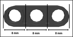
Straight beams are identified by their length, which is measured using a unit of measure referred to as a module. A module is 8mm long, representing the distance between the outer edge of the beam and the center of the space located between its next two closest holes, which is the same as the distance between the center positions on either side of a hole, as depicted in Figure 4.2.
As demonstrated in Figure 4.1, this book identifies straight beams by specifying their length followed by their name. Straight beams come in three colors. The 2M straight beam is black, the 3M straight beam is dark gray, and the 5M through 15M straight beams are all light-gray or white. However, because color is not an attribute that is needed to distinguish one straight beam from another, it is not included in the names of the beams referenced in this book.
With the exception of the 2M straight beam, all straight beams have circular holes at both ends. As shown in Figure 4.3, the 2M beam differs from other straight beams in that it has a circular hole at one end and a cross-hole at the other.

The key difference between circular holes and cross-holes is that when you place an axle in an open hole, the beam is able to spin freely as depicted in Figure 4.4.
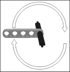
When an axle is inserted into the cross-hole of a 2M straight beam, a rigid connection is made and the beam in not able to move freely.
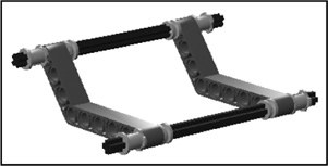
Both circular holes and cross-holes have their own unique purposes. Round holes allow flexibility and facilitate axle movement, which is needed in situations where the axle is connected to a gear or to a rim and tire. Cross-holes are useful in situations where you need to build strong rigid structures, such as the structure shown in Figure 4.5.
Another type of beam included in the Lego Mindstorms NXT 2.0 kit is the angular beam. With angular beams, often referred to simply as angled beams, one or more sections of the beam are angled. Figure 4.6 shows all eight of the angular beams that are provided in the kit.

Angular beams can be used to create complex structures. They can also be used in all sorts of creative ways, such as to create claws for robotic cranes. Like straight beams, angular beams are measured and identified using modules. Angular beams range in size from 5M to 11.5M. Angular beams vary in their degree of angle, with the maximum angle of 90 degrees.
As demonstrated by the 9M angular beam shown in Figure 4.7, most angular beams begin and end with cross-holes, allowing for the creation of rigid connections using axles.

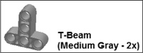
The T-Beam
The final type of beam included in the Lego Mindstorms NXT 2.0 kit is the T-beam. As shown in Figure 4.8, this beam is T-shaped and is 3M wide and 3M tall. This beam consists entirely of round holes. It can be used in various creative ways to connect pieces in ways that other beams cannot.
The largest category of pieces included in the Lego Mindstorms NXT 2.0 kit is composed of the connectors. It includes the subcategories listed here.
Axles
Bushings
Pegs
Angle connectors
Steering links
Cross blocks
Peg blocks
Other connectors
These different types of connectors facilitate connections, allowing you to connect and tie together different Mindstorms pieces into a cohesive whole.
Axles are cross-shaped shafts of varying lengths that can be used to connect to any Mindstorms piece that has a cross-hole connection. Axles are often used in conjunction with gears and servo motors to transmit motion. The Lego
Mindstorms NXT 2.0 kit includes a total of 61 of these pieces as shown in Figure 4.9. Axles can be used in conjunction with cross-holes on beams to create rigid connections and used with circular holes that allow the axles to spin.
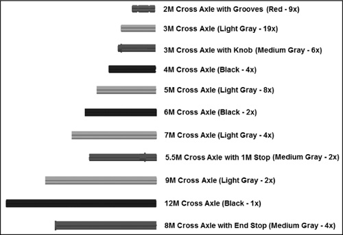
Like beams, the length of axles is measured in terms of modules. Figure 4.9 identifies the length of every axle included in the Lego Mindstorms NXT 2.0 kit.
One of the issues of working with axles is that they tend to slip out of their connections to other pieces. To address this issue, the Lego Mindstorms NXT 2.0 kit includes three types of bushing connectors. Bushings hold their axle’s position firmly, locking other pieces that may be connected to an axle in place. Figure 4.10 shows the three types of bushing connectors supplied in the kit.

Figure 4.11 demonstrates the use of the bushing and half-bushing connectors. The half-bushing connector firmly holds its position on the axle where it is placed. In Figure 4.11 the bushing has been placed at the end of the axle. Any number of other pieces can be placed between these two bushings, and their positions will be firmly maintained.
Figure 4.11. Bushings are used to cap the ends of axles, to hold pieces in place on an axle, or as separators.
Bushings can also be used as separators in order to create space between different pieces attached to an axle. The Bushing 4 Peg piece has characteristics of both bushings and pegs, which are discussed in the next section.
Though small in stature, pegs are big in terms of utility, providing you with the ability to connect beams and other types of pieces that have holes. As shown in Figure 4.12, the Lego Mindstorms NXT 2.0 kit contains 10 different types of pegs. In total, 204 of these pegs are supplied in the kit.
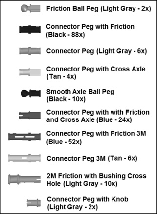
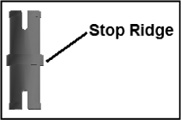
Some pegs are designed to fit circular holes, some are designed to fit cross-holes, and some are designed to fit both types of holes. In addition, pegs are either smooth or friction. Smooth pegs move freely within round holes, whereas friction pegs are designed to firmly hold their position. Regardless of the types of connections that pegs have, one feature common to all pegs is the stop ridge. As shown in Figure 4.13, the stop ridge determines how far the peg can get into a hole.
As demonstrated in Figure 4.14, pegs are used to connect different pieces together. In the case of Figure 4.14, two straight beams are ready to be connected using two connector pegs with friction.
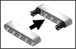
Figure 4.15 shows the result of the previous example, once the two straight beams are connected by pegs. The result is a new sturdy connection.

Another important category of connector is the angle connector, which is used to establish connections between axles. As shown in Figure 4.16, three different types of angle connectors are supplied with the Lego Mindstorms NXT 2.0 kit. Angle connectors can be used to connect two axles and to create 180-degree (straight) connections, to connect two perpendicular axles, and to establish 90-degree connections.
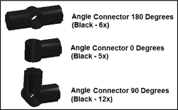
Figure 4.17 demonstrates the use of all three angle connectors. Here, two axles are connected using an Angle Connector 90-Degree connector. Each of the axles is, in turn, connected to a different type of angle connector, allowing for additional connections.
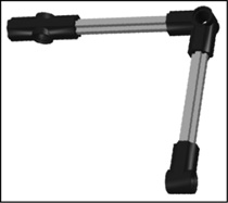
The steering link, shown in Figure 4.18, is designed to establish connections with either the Friction Ball Peg or the Smooth Axle Ball Peg. These connections are very strong. They can be used to add a decorative look or to establish flexible connections in robotic creations that bend, stretch, and move.
Figure 4.19 shows an example of the steering link used to establish a connection between two Friction Ball Pegs.

Cross blocks, shown in Figure 4.20, are a combination of beams and bushings, providing a great deal of flexibility of use. Cross blocks combine circular and cross-hole connections. Cross blocks allow for the establishment of different types of connections. These blocks provide enough variety to tackle most every need and scenario.

Peg blocks are a highly specialized type of peg, combining features of beams and pegs. Peg blocks have circular holes, which run in multiple directions. Peg blocks facilitate parallel and perpendicular connections. The Lego Mindstorms NXT 2.0 kit contains three types of peg blocks, as shown in Figure 4.21.

In addition to all of the different types of connections discussed so far, the Lego Mindstorms NXT 2.0 kit contains three additional connectors that do not fit into any of the previously discussed categories. These three connectors are shown in Figure 4.22.
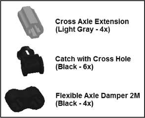
The Cross Axle Extension is used to connect two axles, establishing a longer axle as a result, overcoming any axle length limitations in the kit. The Catch with Cross-hole connector connects axles that intersect perpendicularly. The Flexible Axle Damper 2M connector is used to connect axles that run in parallel and supports robotic creations that require flexibility.
Gears are used to transmit motion. The Lego Mindstorms NXT 2.0 kit provides five different types of gears. As shown in Figure 4.23, a total of 11 gears is provided.
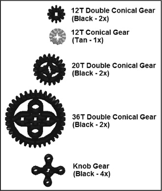
The first four gears shown in Figure 4.23 transmit motion through their teeth while rotating. Gears connect to one another, or mesh, by interlocking their teeth. The rotation of one gear results in the rotation of the gear with which it is meshed. Gears have cross-holes in their centers that are used to connect them to axles. The axles are, in turn, threaded through circular holes in beams and other pieces, allowing them to spin freely.
As shown in Figure 4.23, gears are identified based on the number of teeth they have. The first four types of gears shown in Figure 4.23 are conical gears. Their teeth, as shown in Figure 4.24, are shaped to allow them to mesh with one another when mounted on either a parallel axis or when mounted perpendicular to one another.

The use of two or more gears together creates a gear train. In the example shown in Figure 4.25, two 20T Double Conical Gears have been used to create a gear train using an angular beam. The gear train is pictured twice, providing you with both a frontal and a top view.
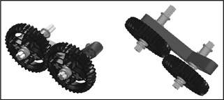
When used in pairs, each gear in a gear train moves in an opposite direction as depicted in Figure 4.26.

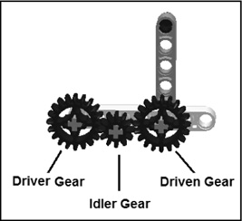
Gear trains can consist of any number of gears. In a gear train the gear that is responsible for transferring motion to the other gears is referred to as the driver gear. It is connected to a server motor via an axle. The last gear in the gear train is referred to as the driven gear. If there are any gears between the driver gear and the driven gear, these are referred to as idler gears. For example, Figure 4.27 shows a gear train made up of three gears.
Trap
As you add more gears to a gear train, more friction is introduced, reducing the overall effectiveness of the gear train. In principle, it is best to keep the number of gears in gear trains as small as possible.
The parts needed to re-create the hand crank shown in Figure 4.27 are shown in Figure 4.28.
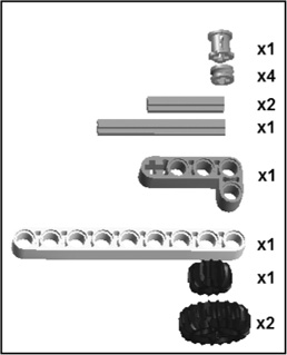
Assembly directions are provided in Figure 4.29.
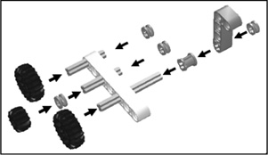
Figure 4.30 depicts the direction that gears move in a gear train made up of three gears. As you can see, each gear moves in the opposite direction of the gear that drives it.

Idler gears are used to bridge gaps between driver and driven gears when they are too far apart to mesh. Idler gears can also be used to control the direction in which the driven gear rotates. Using an odd number of idler gears, you can create a gear train in which the driven gears move in the same direction as the driver gear. Using an even number of idler gears, on the other hand, causes the driven gear to rotate in the opposite direction from the driver gear.
The knob gear does not look like a typical gear. It has four circular knobs that rotate around its axis. The knobs mesh with knobs on other knob gears. Like other gears, it transfers motion from one axle to another, provided the other axle also has a knob gear. Figure 4.31 demonstrates how knob gears work together. Note that knob gears rotate in opposite directions as they mesh together. Like other gears, you can create gear trains using knob gears.

Gear train performance is measured in terms of speed and torque as it affects the driven gear and the axle to which it is connected. Speed is a measurement of how fast the driven gear’s axle is rotated. Torque, on the other hand, measures the strength at which the axle is turned.
You can affect speed and torque by controlling a gear train’s gear ratio. Gear ratio describes the rotation of the driver gear relative to the driven gear. If, for example, a gear train’s driver gear rotates three times for each rotation of the driven gear, its gear ratio is 1:3. Any idler gears in the gear train are ignored. An easy way of calculating the gear ratio is to compare the number of teeth in the driver and driven gears. For example, if the driver gear in a gear train is the 36T Double Conical Gear and the driven gear is also a 36T Double Conical Gear, its gear ratio is 1:1. If, on the other hand, the driven gear is the 12T Double Conical Gear, the gear ratio would be 12:36, which, when simplified, is 1:3. Thus, by changing gear sizes, you can directly affect gear ratio.
If you either decrease the size of the driver gear or increase the size of the driven gear, you are said to be gearing down. In a gear train where the ratio is 1:3, the driver gear must rotate three times in order to make the driven gear rotate one time. The larger the driver gear is in relation to the driven gear, the slower the speed of the gear train and the greater its torque.
If you either increase the size of the driver gear or decrease the size of the driven gear, you are said to be gearing up. When the driven gear is smaller than the driver gear, the speed of the gear train is higher and its torque is lower. As such, gearing up can be used to decrease the torque of a robotic creation and make it go faster.
Another important category of parts includes tracks, rims, and tires. These pieces, shown in Figure 4.32, are essential to any mobile robotic creation, providing them with the ability to move. The rim attaches directly to axles and transfers motion passed through axles to either tires or tracks.

Two rubber tracks are provided in the Lego Mindstorms NXT 2.0 kit and are perfect for making things like tanks, construction vehicles, and other such machines. When used, a track is wrapped around a pair of rims. When the rims turn, so does the track. In similar fashion, you can use tires in place of tracks to create cars and any other type of wheeled vehicle or machine. The tires are made to fit snuggly around the rims.
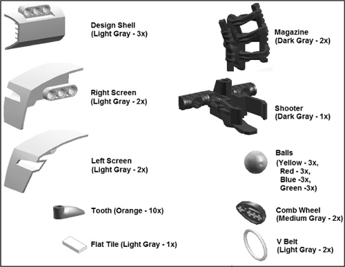
The remaining pieces and parts that make up the Lego Mindstorms NXT 2.0 kit are shown in Figure 4.33. The pieces shown on the left side of the figure are primarily decorative. The pieces shown on the right side of the figure have various purposes. The magazine is used to hold the kit’s balls for using robots that shoot. The shooter provides a means of shooting balls. The kit includes a total of 12 balls, colored yellow, red, blue, and green. The comb wheel connects up to four axles. It can be used in various ways, as a stabilizer for axles or as an attachment that extends the effects of gears. The V Belt is a small rubber band that can be used to loosely bind pieces together.
This chapter rounded out the book’s review of the pieces and parts that make up the Lego Mindstorms NXT 2.0 kit. It focused on all the nonelectric and nonmechanical pieces and parts. This included learning about beams, connectors, pegs, and various other parts groupings. In addition, you learned how to work with gears and reviewed different configurations in which they might be used to transmit motion. This chapter also demonstrated the use of many of the pieces that were covered in order to further enhance your understanding of their usefulness.