
Plasma Arc Speaker
Create a high-voltage loudspeaker that makes sound waves by vibrating an electric arc
Hep Svadja

JOHN IOVINE is a science and electronics tinkerer and author who owns and operates Images SI Inc., a small science company. He resides in Staten Island, N. Y., with his wife and two children, their dog. Chansey, and their cat, Squeaks.
WHAT DO THE WORLD’S MOST EXPENSIVE SPEAKERS, THE SUN, AND LAMPS FROM THE 1890S HAVE IN COMMON? Plasma, the fourth state of matter, of course! After building this little plasma arc speaker, you’ll be able to hear your favorite jams played directly from the vibrating plasma of an electric arc.
Plasma is a high-temperature, highly ionized gas that’s electrically conductive. While conventional loudspeakers use a solid diaphragm, the plasma arc speaker uses ionized gas as a gaseous diaphragm — it’s virtually massless, so it easily responds to high-frequency audio signals. By varying the electrical signal across the electrodes, you’ll cause the ions in the plasma to jiggle, which causes the gaseous diaphragm to vibrate and create sound waves in the air.
THE SINGING ARC
The first instance of a plasma arc speaker can be traced back to William Duddell in 1899. Duddell connected an ordinary carbon arc lamp to a tuned circuit made of a capacitor and inductor, and he discovered that he could generate tones that corresponded to the resonant frequency of the tuned circuit. He wired a keyboard and played “God Save the Queen” on what is considered the first electronic musical instrument — the “singing arc.”
HOW IT WORKS
Most modern published schematics for building “singing arc” speakers use either a 555 timer or a TL494 PWM controller, whose output is wired to a standard power transistor or MOSFET to rapidly switch current on and off to the high-voltage (HV) transformer (Figure A). I chose to use a 555 timer with a unique power component, the insulated-gate bipolar transistor (IGBT), which is ideally suited for this application. It’s got the high current capacity of a bipolar transistor and the voltage control of a MOSFET.

Damien Scogin
The 555 timer is set up in astable mode to continually output a frequency dependent upon an RC network composed of two resistors and a capacitor. This is the oscillation frequency that powers the HV transformer. I chose a “base frequency” of approximately 23kHz because it allows the HV transformer to create an output arc (plasma) that doesn’t produce any sound or tone on its own, as this would detract from the sound quality of the speaker.
Pin 5 on the 555 timer is the control voltage input. By applying a voltage to this pin, we can vary the output frequency of the timer independently from the base frequency that’s set by the RC network. This creates a frequency modulation (FM) output, like FM radio. Just connect the audio output from the 2N3904 transistor to pin 5, and now your audio signal is modulating the output frequency of the 555 timer. This FM output, amplified by the HV transformer, is what jiggles the ions in the plasma arc to create sound.
This small speaker is the equivalent of a tweeter. Large electric arcs can produce better fidelity at lower frequencies, but the smaller arcs in this device are better at reproducing sound in the higher frequencies.
Time Required: 2–5 Hours
Cost: $50–$100
Materials
» Plasma Arc Speaker Kit includes all parts listed below, $90 from Images SI Inc., imagesco.com/kits/plasma-speaker.html
» Heat sink compound
— Or buy the following parts separately —
» High voltage flyback transformer, 40W–80W, 20kV max output available separately from Images SI, part #HVT-01. Designated T1 in the schematic.
» Power jack, 2.1mm P1
» Toggle switch S1
» Resistors, 100kΩ, ¼W (2) R1, R6
» Resistors, 10kΩ, ¼W (3) R2, R5, R7
» Resistor, 1kΩ, ¼W R4
» Potentiometer, multi-turn trimmer, 25kΩ R3, can use 10kΩ–25kΩ
» Capacitor, 470μF, 25V C1, can use 470μF–1,000μF, 16V or higher
» Capacitor, 0.001μF, 100V C2
» Capacitor, 330pF, 50V C3
» Capacitors, 10μF, 16V (2) C4, C5
» Capacitor, 0.1μF, 100V C6
» LED, submini, green D1
» Audio jack, 3.5mm J1
» 555 timer IC chip, LM555 U1
» IC socket, 8-pin
» Transistor, 2N3904 Q1
» Transistor, IGBT, ISL9V5036P3 Q2, also available separately from Images SI
» Large heat sink for IGBT
» Fan, 12VDC, 40mm×20mm
» Plastic tube, 3" diameter, 4" length
» Binding post, black
» Binding post, red
» High voltage wire, 12"–18" length
» Wire, 22–20 gauge, solid insulated, 12" length
» Power supply, 12VDC, 2A or greater
» Plastic project enclosure
Tools
» Soldering iron
» Wrench or pliers
» Rotary cutting tool
» Drill and drill bits
» Breadboard (optional) if you’re not using the custom PCB from the kit

CAUTION:
HIGH VOLTAGE CAN BE LETHAL
If you’re not familiar with working with high-voltage devices, we do not recommend you build this device. If you have a weak heart or an implanted biomedical device like a pacemaker, do NOT build this device. Safe assembly and operation of this project is the user’s responsibility. A high voltage may cause you to jump, move, or fall, and can thereby cause a secondary injury unrelated to the electric shock itself. Take the following precautions and treat all high-voltage power supplies with the respect they deserve.
BASIC SAFETY GUIDELINES
» Keep one hand in your pocket. Only use your other hand to work with the high-voltage equipment. This reduces the probability of accidentally passing high-voltage current across your heart from hand to hand.
» Set up your work area away from possible grounds that you may accidentally contact. Keep your work area neat and clean to easily identify high-voltage wires and grounds.
» Be sure the floor is dry and wear rubber-soled shoes.
» Prove to yourself the high-voltage power supply is off — by unplugging the device’s electrical power cord. Don’t trust power switches that could be accidentally turned on.
» Do not work on high-voltage apparatus when you’re tired or not alert.
» High voltage could jump to the low-voltage side of the circuit and damage the audio player. Use only inexpensive audio devices. We are not responsible for any damage to your audio devices.
For more safety guidelines, visit the project page at makezine. com/go/plasma-arc-speaker
1. BUILD THE CIRCUIT
Solder the components to the printed circuit board (PCB) included in the kit (Figure B). If you’re not using the kit, you can prototype the circuit using point-to-point wiring, following the schematic (Figure A). You can use a solderless breadboard for the low-current components only, like the 555 timer, 2N3904 transistor, and audio input. (While the circuit as a whole draws less than 2A of current, that’s still above the rating of solderless breadboards.)

NOTE: If you’re using a different HV transformer, you may need to adjust the base frequency of the 555 timer in order to achieve a “silent” high-voltage plasma arc. Experiment with the resistor and capacitor values of the RC network (R5, R6, and C3) to tune the base frequency until a silent electrical arc is achieved.
Spread heat sink compound on the back of the IGBT and make sure there’s good contact with the heat sink to ensure good heat transfer (Figure C).

2. MOUNT IT IN THE ENCLOSURE
The output of this circuit generates high voltage — be careful near the output of the HV transformer! — so you’ll mount it in a plastic enclosure, as plastic is an insulator and will be safer than a metal enclosure. First, connect the high voltage wires to the output of the HV transformer; you will run these out to the binding posts of the plasma speaker tube.
Drill and cut holes in the enclosure for the fan venting, power jack, audio input, LED, switch, and high voltage wires (Figure D), following the template on the project page at makezine.com/go/plasma-arc-speaker.

IMPORTANT: The large IGBT heat sink and 12VDC blower fan are essential. Mount the fan close to the heat sink to maximize cooling, and make sure your enclosure has large circular cutouts for intake and exhaust to permit sufficient airflow for cooling. Without taking these actions, your IGBT will overheat in less than a minute.

3. BUILD THE PLASMA SPEAKER TUBE
The speaker is fabricated out of a 4" length of 3"-diameter clear plastic tubing. Cut 3 notches in the bottom of the plastic tube to create legs and to allow airflow. (The arc can get as hot as a candle.)
Drill holes on opposite sides of the tube, 1¼" from the top, sized to accept the binding post terminals (Figure E).

Damien Scogin
4. ATTACH THE ELECTRODES
To make the electrodes, solder a length of 22–20 gauge solid wire to the solder tab of the binding post terminal. If your terminal doesn’t have a solder tab, simply wrap the wire around the inside binding post screw.
Secure each binding post with a nut, then attach the high-voltage wires from the transformer (Figure F).

5. PREPARE THE CIRCUIT FOR AUDIO INPUT
By turning potentiometer R3 with a small screwdriver (Figure G), you can fine-tune the bias for the audio signal to the NPN transistor amplifier. Adjust potentiometer R3 to its midpoint position before turning on the plasma arc speaker.

The audio input signal I used was 100mV (0.1V) peak to peak from an iPod. If the audio signal is too large it will be clipped, creating distortion in the plasma speaker’s output. If your plasma arc speaker sounds terrible, the first thing to do is to reduce the volume of your audio signal going into the circuit. Less may be more.
6. ROCK SOME TUNES!
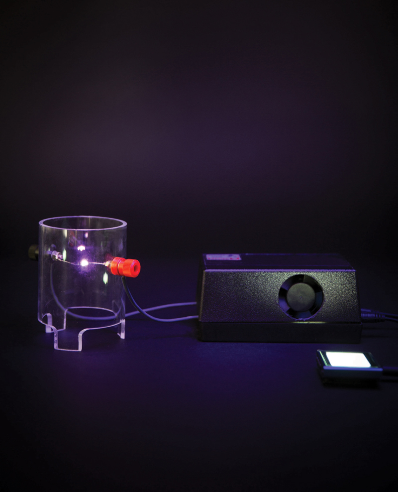
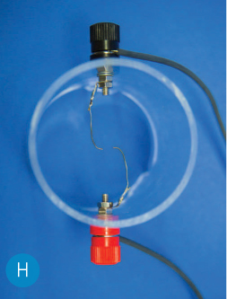
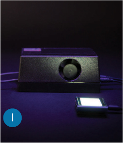
Before you turn on your plasma arc speaker for the first time, adjust the electrodes so the wires are arced and the ends of each wire face each other (Figure H). This is to ensure that the electric arc forms between the wire ends, which will provide the best audio quality. If the arc travels up and down the side of the wire, you’ll hear distortion. Adjust the gap between the wire ends to approximately ¼". Then connect your audio player to the circuit’s audio input, and press Play (Figure I).
Power up the speaker, and adjust the volume as necessary to form an arc (Figure J). If an arc doesn’t form, make sure audio is being played. If the arc still doesn’t form, switch the speaker off, unplug it, and then adjust the gap as necessary.

With your plasma arc speaker, you’ll be rocking tunes with the same tech-nology that high-dollar audiophile speakers use!
FURTHER EXPERIMENTS
» Crossover To use your plasma arc speaker as a tweeter to complement your existing hi-fi speakers, try the bass crossover circuits used by Paul Faget (github.com/paulfaget/PlasmaArcSpeaker) or Oliver Hunt (hvlabs. com/plasmasonic.html).
» Flame Speaker You can even use a high-temperature flame (low-temperature plasma) as the gaseous membrane to generate sound. Learn more on the project page online! ![]()
+ More high voltage makers: Richard Hull and the High Energy Amateur Science group do great things with Tesla coils and fusors at tfcbooks.com/mall/hull.htm and teslauniverse. com/community/groups/heas-tcbor
See the plasma arc speaker in action, try more experiments, and share your build on the project page at makezine.com/go/plasma-arc-speaker
MORE HIGH-VOLTAGE PROJECTS AND KITS FROM MAKE:
Complete your mad scientist’s laboratory

SIX-PACK TESLA COIL
Construct an awesome lightning-arcing coil based on Nikola Tesla’s discoveries, using beer bottles as capacitors. makezine.com/go/six-pack-tesla-coil
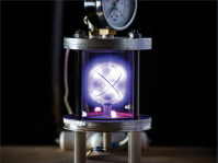
NUCLEAR FUSOR
Build the purple-glowing, ion-accelerating, mini fusion reactor developed by Philo T. Farnsworth, inventor of television. makezine.com/go/nuclear-fusor
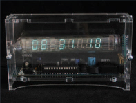
ICE TUBE CLOCK KIT
Old-meets-new clock uses a Russian-made vacuum fluorescent display (VFD), vintage 1960s-80s. Get it from the Maker Shed! makezine.com/go/ice-tube-clock-kit