
Build a Twilight Photometer
This ultra-sensitive device detects the altitude of dust, smoke, and volcanic emissions high in the sky
Written and photographed by Forrest M. Mims III ![]() Illustrated by James Burke
Illustrated by James Burke
HAVE YOU WONDERED WHY SOME SUNSETS ARE SO SPECTACULAR AND OTHERS SO DRAB? This ultra-sensitive photometer project will allow you to tease out the secrets of twilight and even do serious science by finding the altitude of the dust, smoke, and air pollution that influence the colors of twilight.
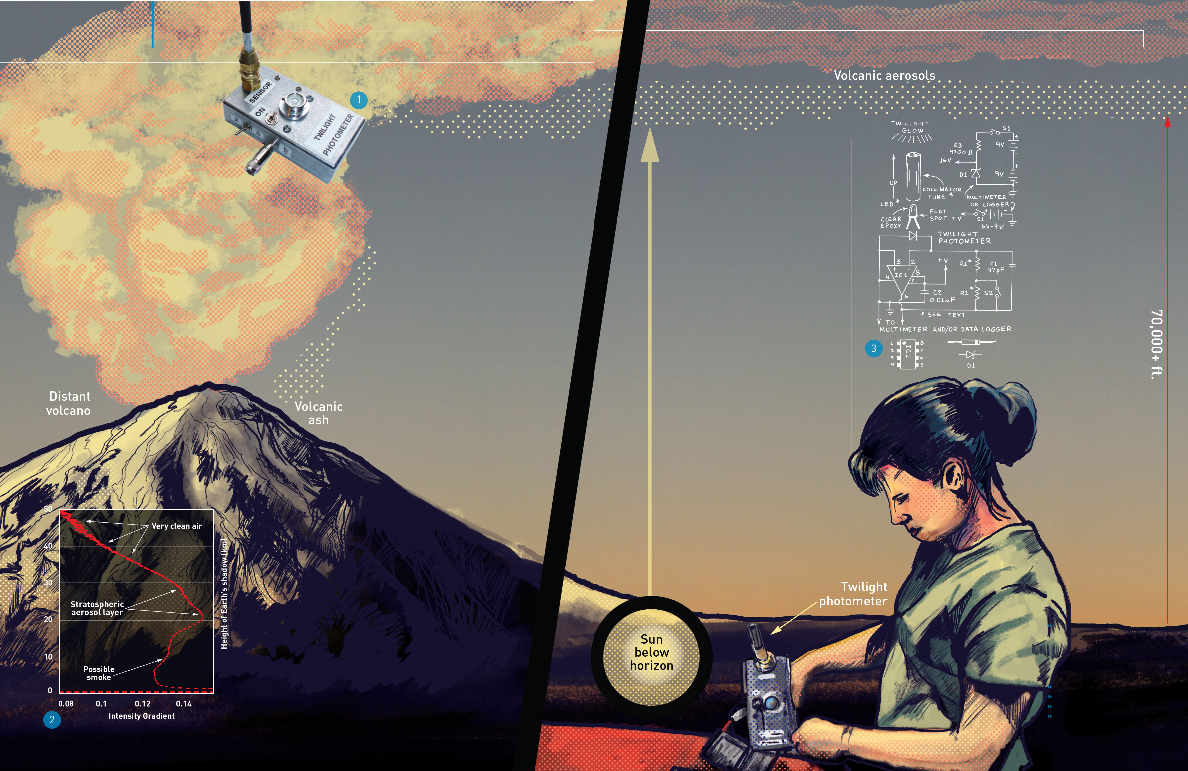
With this project you can detect the tiny particles and droplets known as aerosols from 3km (around 10,000 feet) high to well above the top of the stratosphere at 50km (165,000 feet). While the photometer will not detect aerosols below 3km, many of those particles eventually float high enough to be detected. For example, from my Texas site I’ve measured the altitude of smoke from distant fires, haze caused by faraway power plants, and African dust that arrives every summer.
You can even measure the altitude of the sul- furic acid mist that forms an immense blanket 15km–30km high around our entire planet. This stratospheric aerosol layer, which major volcano eruptions can significantly enhance for several years or more, controls the duration of twilights and even influences climate.
BUILD A SIMPLE TWILIGHT PHOTOMETER
The twilight photometer shown in Figure 1 requires no optics and is considerably simpler, smaller, and cheaper than those used by professional scientists. Yet, as shown in Figure 2, it nicely estimates the altitude of dust and smoke clouds from 3km to 15km in the troposphere and the permanent aerosol layer at around 15km–30 km in the stratosphere. Instead of a conventional photodiode, the twilight glow is detected by an ordinary 660nm red LED or an 880nm near-infrared LED like those used in remote controls for TVs and appliances.
HOW IT WORKS
The twilight glow straight overhead is very dim, and the photocurrent it generates in an LED is very small. Therefore it’s important to use an LED installed in clear epoxy. For best results, use an LED that projects a narrow beam when used as a light source. (For details about using LEDs to detect light, see this column in Make: Volume 36.)
The photometer circuit is shown in Figure 3. In operation, the tiny LED photocurrent is amplified billions of times and transformed to a voltage by IC1, a TLC271BIP operational amplifier with a very high-resistance feedback resistor consisting of R1 and R2 in series. Capacitor C1 suppresses oscillation. The combined resistance of R1 and R2 controls the voltage gain of the amplifier. I have obtained best results using 40-gigohm resistors for both R1 and R2. When only 40 gigohms is required to provide a usable output signal during the 30–45 minute twilight period, switch S2 is closed to bypass R2. High-value resistors can be expensive and difficult to find, but I’ve had good results with Ohmite resistors from Mouser Electronics (mouser.com) and Digi-Key (digikey.com). For example, Mouser offers Ohmite’s 40-gigohm axial-lead resistor (MOX-400224008K) for a reasonable $4.19 each. If 40-gigohm resistors aren’t available, use 30- or 50-gigohms.
PLANNING THE PHOTOMETER
The twilight photometer should be installed in a metal housing to block electrical noise from power lines and radio signals. I learned this lesson the hard way while testing my first twilight photometers at Hawaii’s Mauna Loa Observatory. The LED can be installed inside the enclosure with a small hole to admit the twilight glow, or inside an open-ended phone or audio plug fitted with a collimator tube and inserted into a jack atop the enclosure. I’ve used both methods and much prefer the external method described here for initial experiments. This allows you to try various LEDs and collimator lengths. After you find the optimum combination, you can install the system inside an enclosure.
FORREST M. MIMS III (forrestmims.org), an amateur scientist and Rolex Award winner, was named by Discover magazine as one of the “50 Best Brains in Science.” His books have sold more than 7 million copies.
Materials
» Capacitors, ceramic: 47pF (1) and 0.01μF (1) designated C1 and C2, respectively
» Zener diode, 16V D1
» Operational amplifier (op-amp) IC, TLC271BIP IC1
» LED with clear capsule, 660nm red or 880nm near-IR
» LED socket (optional)
» Resistors: 40GΩ (2), 4.7kΩ (1) Use the 40-gigohm resistors for R1 and R2 (see text).
» Switches, miniature SPST S1 and S2
» Batteries, 9V
» Battery connector, 9V, with wire leads
» Battery support bracket (optional)
» Audio or phone plug and jack, 1/8"
» Output plug and jack compatible with your data logger
» Insulated standoffs (2) RadioShack #2761381 or similar
» Perforated circuit board, 1½"×1¼" with copper pads
» Metal enclosure
» Brass compression union fitting, 3/8" from hardware store
» Aluminum or brass tube, about 4" length from hobby shop; to fit over your LED
» Bubble level
» Hookup wire and hardware
Tools
» Soldering iron and solder
» Drill and bits
» Multimeter
» Screwdriver
» Data logger (optional)
Two 9-volt batteries connected in series power the photometer. Because IC1 must not be powered by more than 16 volts, the 18 volts from the two batteries is reduced to 16 volts by Zener diode D1. This arrangement provides the maximum possible output voltage range for a data logging multimeter. If you plan to use a DIY or commercial data logger instead (see Part 2 of this project in our next issue, Make: Volume 45), the circuit’s output voltage must not exceed the data logger’s allowable input voltage. This is typically 5 volts, which means you can power the photometer with a 6-volt battery instead of D1, R3, and the two 9-volt batteries. Both power options are shown in Figure 3. If the logger’s input must never exceed 5 volts, insert a 1N914 diode between the positive battery terminal and IC1.
ASSEMBLE THE CIRCUIT
The circuit is built on a 1½"×1¼" perforated board with copper traces on the bottom. The prototype board is shown in the open view of the photometer in Figure 4.

For best results, the op-amp’s input (pin 2) should be isolated from the circuit board to prevent dust, fingerprints, and even the board itself from altering the gain of the op-amp. Isolating pin 2 in free air eliminates this problem. The easiest way to do this is to provide an 8-pin IC socket for IC1. Before inserting IC1 into the socket, bend pin 2 straight out so that it doesn’t touch the socket when the other seven pins are inserted.
The next two steps are tricky, so refer to Figure 5 and take your time. First, solder the input side of R1 and C1 directly to pin 2. Then solder a wire directly between pin 2 and the LED cathode (–) terminal of the phone or audio jack.

INSTALL THE CIRCUIT IN AN ENCLOSURE
After the circuit board is assembled, clean the surfaces of R1, R2, and IC1 with a cotton swab dipped in alcohol. Then install the circuit board atop a pair of insulated standoffs inside a metal enclosure as shown in Figure 4. The photometer described here was installed in a Bud Industries CU-124 enclosure. A larger enclosure can be used, as can various metal containers sold by craft stores. If you use two 9-volt batteries (as shown in Figure 4), secure them in place with an angle bracket.
Figure 6 shows a pair of LED-collimator assemblies made from a gas coupler fitting and an aluminum or brass tube. The LED is inserted into an LED socket (optional) soldered to 1/8" phone plug terminals or soldered directly to the phone plug. [IMPORTANT: Be sure to observe polarity.] The phone plug is pushed into the open end of the lower coupler fitting and secured in place with a rubber O-ring.

You can omit the gas coupler if the plug’s cap will slip over the LED, which means its leads must be clipped close and carefully soldered. Insert the open end of the plug into an appropriate collimator tube. A collimator length of 3"–4" should provide a field of view of around 5 degrees. As shown in Figure 6, the length of the collimator can be increased or decreased with a short length of heat-shrink tubing.
USING THE PHOTOMETER
On a clear day 10 minutes before sunset or 45 minutes before sunrise, place the photometer facing straight up on a level surface outdoors well away from light sources. A bubble level mounted atop the photometer will simplify alignment. If necessary, use shims to level the photometer. For best results, connect the photometer output to a data logging multimeter or a standalone DIY or commercial logger (Onset 16-bit HOBO UX120 or similar) and record data at 1-second intervals. If you don’t have a logger, read the output voltage manually from a multimeter at 10- or 15-second intervals and enter the exact time and output voltage into a notebook or audio recorder. Automatic logging is preferable, but the manual method has been used for half a century.
GOING FURTHER
The raw twilight signal should provide a smooth curve when plotted on a graph of time vs. signal. Far more significant is a graph that plots the rate of change in the data against the elevation of the twilight glow. Part 2 of this project in Make: Volume 45 will explain how to process your data so that it accounts for these parameters and reveals the altitude of aerosols over your location. Meanwhile, you can learn much more about the science of twilight photometry at makezine.com/go/twilight.
Share your build and twilight observations at makezine.com/go/twilight-photometer.