
Chapter 5
Letter Magnets
Working with Light-Emitting Diodes (LEDs)

In the modern world, we often see electronic signs, made of out of light-emitting diodes (LEDs), that are scrolling or flashing letters and words. These signs might tell us about anything from construction on the highway to the price of a sandwich in a deli. No matter what you want to say, to make letters with LEDs, you need to use a lot more LEDs and electrical connections than you have in your previous projects. In this chapter, you will learn about a few new concepts having to do with electric current, voltage, and resistance. In this project, you will make refrigerator magnets, like the ones in Figure 5-1, that are made up of many LEDs in the shapes of letters. You will use parallel circuits just like you did in the ghost project in Chapter 4 to make this magnetic alphabet.
 Learn
Learn
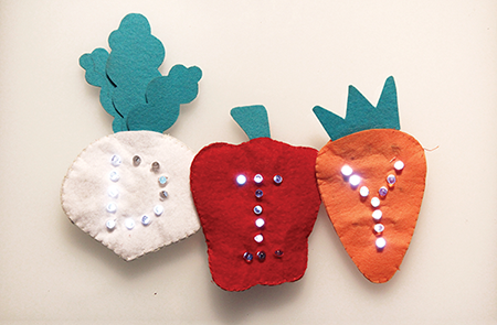
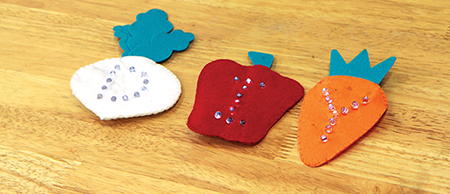
Figure 5-1: Making your own light-up refrigerator magnets
In order to understand how to use many LEDs, it helps to know a bit more about the relationships between electric current, voltage, and resistance.
Electric Current
You can think of the electric circuit in a wire as being like water flowing through a pipe. In this case, the battery plays the role of a water storage tank, with gravity pushing electrons (water) through the wire (pipe). To continue this analogy, the quantity of water that passes by one point in the pipe over the course of one second is called the current. Likewise, electric current is a measurement of the number of electrons per second that are flowing past a given point in a circuit (see Figure 5-2). Electric current is measured in amperes, or amps for short.
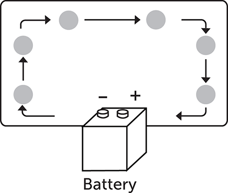
Figure 5-2: Electrons moving through a circuit
Voltage
You can think of voltage as the pressure that pushes an electric current through a wire. Take a look at Figure 5-3. In our water analogy, the voltage is the pressure, due to earth’s gravity, of the water in the storage tank pushing water through the pipe (1). If you double the amount of pressure by doubling the amount of water in the tank (2), this is like connecting two of the same batteries in a series—the voltage will double. But if you set up two storage tanks in parallel (3), the pressure remains the same, but the amount of water flowing through the pipe doubles. In this case the voltage is the same, but the current doubles. Voltage is measured in volts.
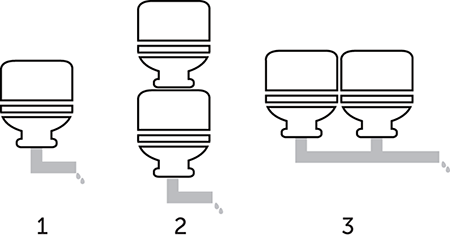
Figure 5-3: Water in a storage tank pushing water through a pipe
If we put two 3V (3-volt) batteries in a series and connect them to a light, the voltage across the light will be 6 volts (see Figure 5-4). That light will shine brightly and probably burn out quickly!
On the other hand, if we put two 3V batteries in parallel and connect them to the light, the voltage remains the same (see Figure 5-5). The light will shine at the same level as if there was one battery, but the batteries will last twice as long.
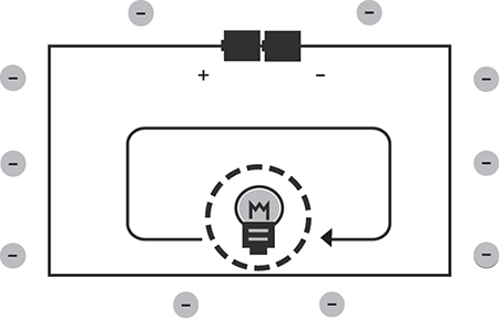
Figure 5-4: With two batteries in a series, the voltages of the batteries add up to the total voltage across the light.

Figure 5-5: With two batteries in a parallel circuit, the voltage is the same as with one battery, but the charge will last longer.
Resistance
Any component in an electrical circuit will resist the flow of electrons in that circuit. The amount of resistance is measured in ohms. The symbol for ohm is the Ω. When you increase the amount of resistance in a circuit, the number of electrons flowing past any point decreases, so the current also decreases. In our water analogy, an increase in resistance could be caused by narrowing our pipe. A wide pipe allows a lot of water to flow through, so we say the current is high and the resistance is low. If we pump water through a narrower pipe at the same pressure, less water flows through that pipe over the course of a second, so we say the current is lower and the resistance is higher.
Relationship between Electric Current, Voltage, and Resistance
Since LEDs resist electric current, as you add more LEDs, the current decreases. This is not usually a problem when you are using two or three LEDs, but as you add many more, the current might get so low that your LEDs might start to dim or stop working altogether. There is a relationship between voltage, current, and resistance that allows you to figure out how much power you need to provide when you’re working with many LEDs. This relationship is called Ohm’s law.
This law tells you that if you increase the voltage in a circuit, you will increase the current. However, if you increase the resistance in a circuit, you will decrease the current. Your battery provides the voltage, and that remains basically constant (however, it does go down as the battery drains). Therefore, when you add more LEDs, the resistance in the circuit increases and the current decreases. But by adding a second 3V coin cell battery in parallel (see Figures 5-6 and 5-7), you increase the current and you can provide enough current for up to ten LEDs. You can use Ohm’s law to calculate what kind of battery or batteries to use and how to regulate resistance in your circuit.

Figure 5-6: Adding a second battery in parallel doubles the current.

Figure 5-7: A circuit diagram of two batteries in parallel powering eight LEDs
 Make
Make
Use Your Imagination
What are some of your ideas for using many LEDs in a circuit? How about making light-up letters from the alphabet? If you make several of these letters, then you can order and combine them to spell words! What letters do you want to make? What words do you want to be able to spell? In this project, we are going to put our letters on vegetables. Start by making a sketch of your project as in Figure 5-8. Make your sketch life-size and make sure that you have enough room for all of the components in your circuit.
Figure 5-8: A sketch of a pepper onto which we are going to sew a circuit with many LEDs
Plan It Out
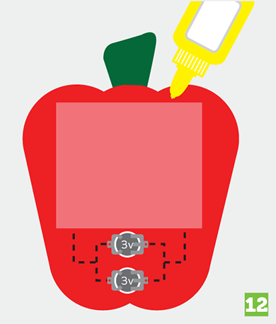
After you have sketched the project, add your circuit diagram to the sketch. Since you will form letters by connecting many LEDs in parallel for this project, it’s really important to separate the positive and negative sides of your circuit. You are going to connect all of the positive legs of the LEDs to the positive sides of the batteries and all the negative legs of the LEDs to the negative sides of the batteries. Make sure to use no more than ten LEDs and connect two batteries to your circuit in parallel as illustrated in Figure 5-9.

Figure 5-9: A sketch of the pepper that includes the circuit diagram. The positive side of the circuit is red. The negative side of the circuit is black.
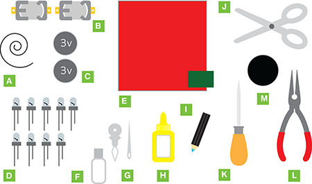
Preparation
After you are done sketching and carefully planning the circuit, it is time to collect your materials, cut out your fabric, and sew your circuit. Since this circuit includes many LEDs, you have to be extra careful that you don’t cross the threads of the positive and negative sides of the circuit. Take your time. Try to make each stitch as neat as possible. When you are looping the thread around the curled legs of your LEDs, loop it a few times to get a good connection, and then move on to the next LED.
Make It
Follow these steps to make a light-up letter project with several LEDs:
- Use a chalk pen to sketch the outside of your shapes on felt sheets.
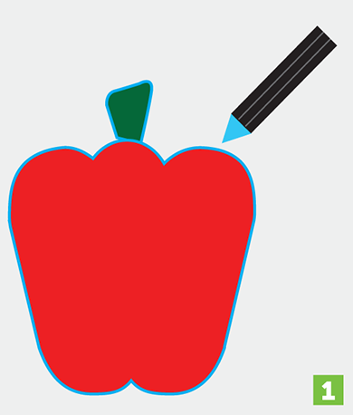
- Cut out the shapes and use fabric glue to paste any pieces together.
- Use a chalk pen to lightly draw dots in the pattern of your letter for the legs of the LEDs. Mark the positive and negative sides of your project to remind yourself to keep the positive holes on one side of the circuit and the negative holes on the other side of the circuit. Make sure to leave room on the felt for the batteries.

- Using an awl, or other sharp tool, carefully poke holes for the legs of the LEDs.

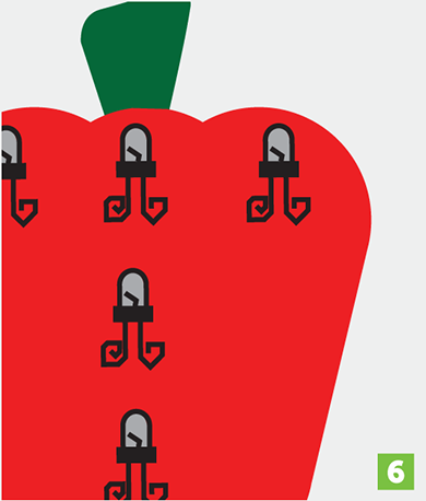
- Place the legs of your LEDs into the holes from the front so that the legs come through to the back of the felt. Take extra care to make sure that the positive (long) legs and the negative (short) legs go into the correct holes.
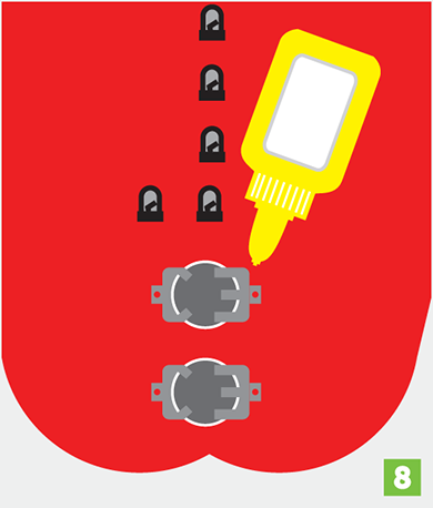
- Use needle-nose pliers to curl the legs of the LEDs on the back of the felt sheet as you have done for the previous projects. Take extra care to make sure that the positive and negative legs of the LEDs don’t touch each other. Note that in these images, the lights of the LEDs are shown on the back for clarity.
- Place the battery holders on the felt sheet. Double check the orientation of the battery holders. Make sure the positive and negative sides are facing in the same direction as the LEDs.
- Glue the battery holders to the felt.
- Now you can start sewing your circuit. Use conductive thread to connect the positive sides of your battery holders together. Then use another piece of conductive thread to connect the negative sides of your battery holders together.

- Next, use the conductive thread to connect all of the positive legs of the LEDs together.
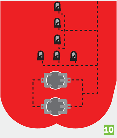
You can use the same piece of thread to connect all the LEDs; just loop it through each curled leg twice to get a good electrical connection, and then tie the thread to the positive connection of the battery holders.
- Repeat the last step with the negative side of the circuit.
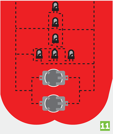
- Now insert batteries into the holders to test your circuit.
Once you are sure that your circuit is working, cover the circuit with a sheet of felt and glue it down. This is to prevent a short circuit if you attach your letter to a metal surface. Make sure not to cover the battery holders so that you can still change the batteries once they run out of charge.
- Finally, glue a magnet to the back side of the felt.
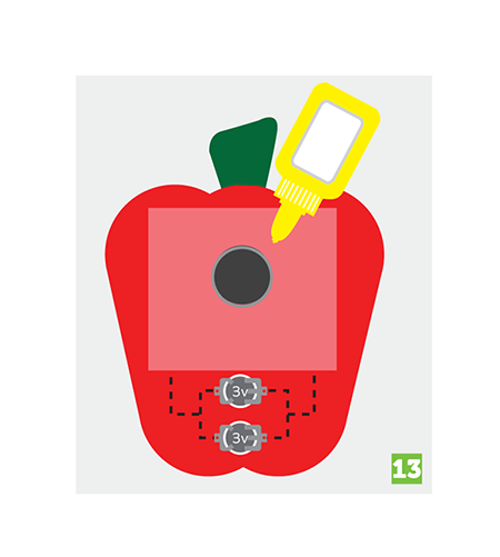
Figure 5-10 shows what the back side of the finished magnet looks like.

Figure 5-10: The back of a turnip with a felt sheet covering the circuit and a magnet attached
Now you’re all done (see Figure 5-11)! Place your magnetic LED letters on your refrigerator or any other metal surface.

Figure 5-11: Completed LED letter magnets
 Explore
Proudly show off your project. Make a word with your letters and take a picture or share with your friends and family.
Now it’s time to explore some other works that use electric current, voltage, and resistance to light up many LEDs.
Figure 5-12 shows a ladybug with firefly aspirations.
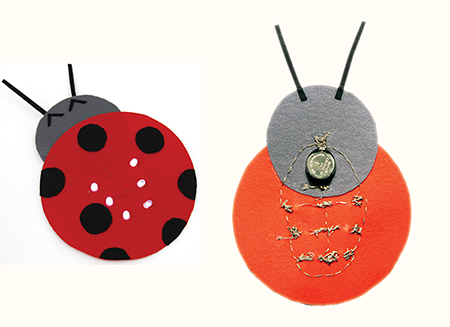
Figure 5-12: A light-up ladybug (front and back)
Which Legs Turn On the Light?
This monster octopus with many eyes (see Figure 5-13) was made by an elementary school student. Since the child wanted to add some sort of playful component to the project, only two of the legs turn on the monster’s eyes when they are connected to each other.
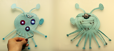
Figure 5-13: Playful octopus (front and back)
Flower Decorated Headband

This headband was the result of a collaboration between an adult and a child. Some young girls like headbands that attract attention. The LEDs serve that purpose. How might you add a switch to this project so that you can turn it on and off when you need to?
The Secret Tree
LEDs are used in a lot of technological artwork because they are inexpensive and they have a nice visual effect. But as you learned, when you are using many LEDs, it can be difficult to maintain the optimal relationships between voltage, current, and resistance.
I made the Secret Tree project that appears in Figures 5-14–5-17 so people could share their secrets. I exhibited this tree at a Maker Faire in Texas during the fall of 2008. If you confessed your secrets to the tree, a microphone would record your voice and then scramble the words. You could also interact with the tree to hear the scrambled voices of past confessions. This made it possible to recognize voices, but the content of the confessions were unrecognizable. I added moonlit flowers to the tree that brightened and dimmed according to the volume of the voices of the people recording their confessions.

Figure 5-14: A moonlit flower on the Secret Tree
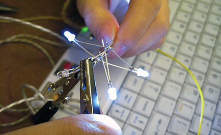
Figure 5-15: Testing the circuit for the Secret Tree
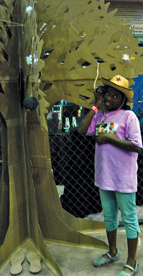
Figure 5-16: Listening to scrambled confessions from the Secret Tree

Figure 5-17: Confessing secrets to the Secret Tree
I started prototyping this project with parchment paper and LEDs that I connected in parallel.
As you can imagine given the size of the final tree and the many moonlit flowers, I had to use Ohm’s law to determine the proper power source that I would need to power the hundreds of LEDs in the project.
If you understand how to use Ohm’s law, you can apply it to many types of projects. Figures 5-18 and 5-19 show a recycled shopping bag that I turned into a miniature version of the secret tree.

Figure 5-18: Recycling materials for projects
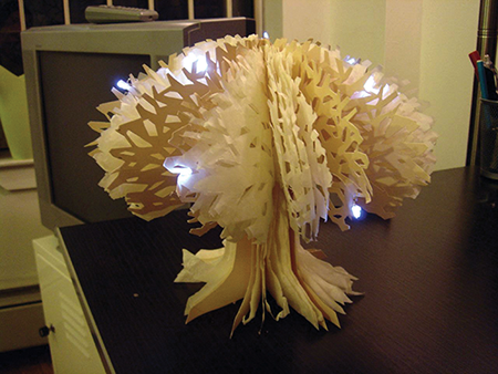
Figure 5-19: A miniature version of the Secret Tree made from recycled materials
What’s Next?
So far you have been making circuits with LEDs; it’s really fun to make things that light up. But in the next chapter, you’ll do something even more fun; you will learn how to use a vibrating motor to make a project that moves!