
Chapter 8
A Beeping, Blinking UFO
Using the 555 Timer

Now that you know how to turn on and off light-emitting diodes (LEDs) using switches and light sensors, you are ready to learn how to make an LED blink on and off all by itself. For this project, I am going to introduce a new type of electronic component called an integrated circuit (IC). An integrated circuit, commonly called a microchip, is just a tiny circuit inside a plastic case. You’ve probably seen ICs inside electronics or computers. For this project, you will use a very popular IC called a 555 timer to make a blinking and beeping UFO.
 Learn
Learn
To make this project, you are going to have to learn a bit more about integrated circuits and how to use them. You will also learn how to use another electronic component called a capacitor.
Integrated Circuits (ICs)
An integrated circuit is really just a tiny circuit that includes several electronic components like resistors and transistors inside of a plastic case. You can connect to this circuit through the metal legs, called pins, that come out of the case. Many types of integrated circuits can perform many different functions. Some ICs act as counters, amplifiers, memory storage devices, microprocessors, and more.
555 Timer
The IC that we are using for this project is called a 555 timer (see Figure 8-1). The 555 timer is a popular chip with many uses. This IC is a type of oscillator, or a circuit that allows you to vary the voltage coming from one of the pins on the IC in a wavelike pattern. If you can get the voltage to go up and down in a regular pattern, then you can use that changing voltage to get an LED to blink on and off. The 555 timer can generate electrical pulses, or oscillations, with intervals from over one hour to only 0.00005 seconds! The 555 timer has eight pins to which you can connect your circuit. To use any IC, you need to know how to connect it to your circuit. For this, you can use a pinout diagram like the one shown in Figure 8-2.
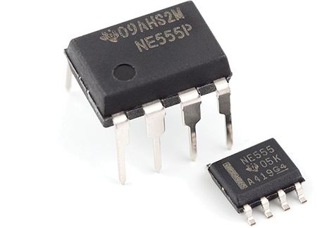
Figure 8-1: A 555 timer
Photo credit: https://upload.wikimedia.org/wikipedia/commons/thumb/6/64/NE555_DIP_%26_SOIC.jpg/1280px-NE555_DIP_%26_SOIC.jpg

Figure 8-2: The 555 pinout diagram shows the function of each pin on the 555 timer.
An important note about sewing circuits with integrated components: The legs, or pins, on ICs are very small and close together. It would be really difficult to sew directly to them. As a solution, you can use a specially designed circuit board called a breakout board. When you plug a 555 timer into a breakout board, then the pins of the IC are connected to holes that spread out, and these are easy to connect to with your conductive thread (see Figure 8-3). For a list of suppliers for this part, please visit the website for this book at www.techdiy.org.
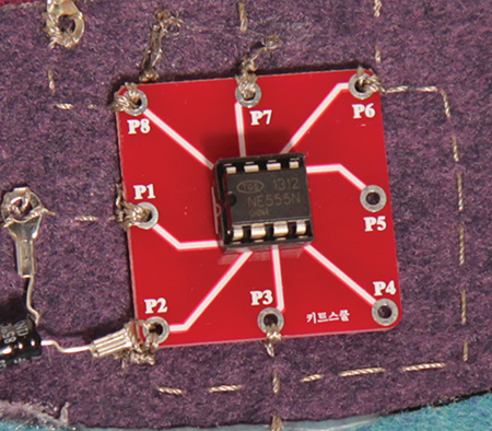
Figure 8-3: 555 timer on a breakout board
Capacitors
A capacitor is used to store electrical charge in a circuit. Similar to the way your body builds up static electricity in the winter and then releases it when you touch a doorknob, a capacitor allows the electrical energy between two separated plates to build up until it is so great that the electricity jumps across the plates, discharging the capacitor in the process. Capacitors are helpful for absorbing and stabilizing voltage as well as for charging and discharging electricity as a battery does (see Figure 8-4). The amount of charge that a capacitor can hold is measured in farads. Common capacitors store microfarads for softening voltage changes or for controlling short intervals of electrical signals. A super capacitor has 1,000 times more storage capacity than a common capacitor.

Figure 8-4: The two separated plates of a capacitor allow electrical charge to build up until it is so great that the electrons jump across the gap between the plates.
The Circuit
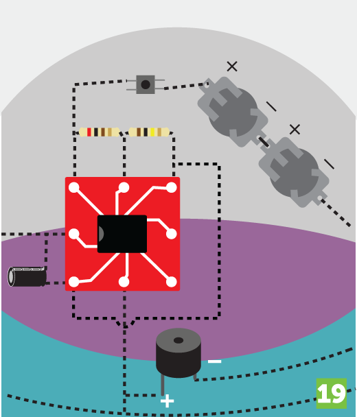
The circuit diagram in Figure 8-5 shows how to blink two LEDs using a 555 timer, a 10 microfarad (uF) capacitor, a 200 ohm resistor, and a 10,000 ohm (10k ohm) resistor. The 10k ohm resistor, shown here between pins 6 and 7, is used to control the rate of blinking. If you increase the size of that resistor, the blinking will slow down. As shown in Figure 8-5, you can also add a buzzer in a parallel circuit with two LEDs to make your UFO beep as well as blink.
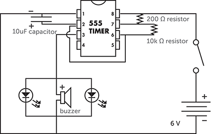
Figure 8-5: The 555 timer circuit for blinking LEDs and beeping a buzzer
 Make
Make
Use Your Imagination
The circuit in Figure 8-5 makes two LEDs blink and a buzzer make a beeping sound. What suitable project ideas can you come up with that blink and beep? Use your imagination. In our example project, we are going to make a UFO. Make a life-size sketch of your project like the one in Figure 8-6.
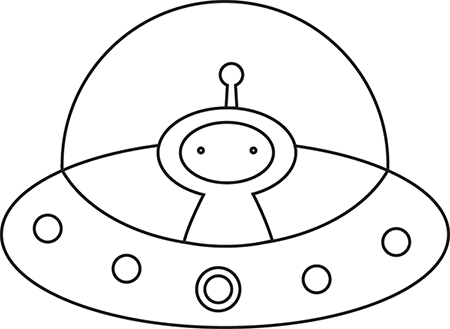
Figure 8-6: The front of our UFO project
Plan It Out
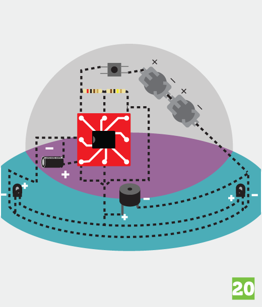
Once you have decided on your design and sketched it out, check out the circuit diagram in Figure 8-7 to decide where to position your components and how to connect them with conductive thread. Draw your circuit on the back of your project sketch. Give yourself plenty of room because this is a complicated circuit with many components and connections. It is a good idea to place the 555 timer near the middle of your circuit. You can then put the rest of your components on your circuit diagram to make sure you haven’t made any mistakes and that you have enough room for all the pieces of the circuit.
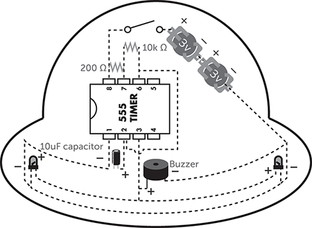
Figure 8-7: The circuit diagram for our UFO project
Preparation
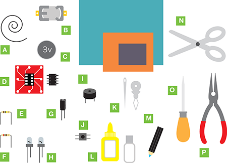
After your have sketched and planned out your project, you are ready to gather your materials and begin making it. Be aware that as your circuits get more complicated, with more components and more connections, you really have to be careful that you don’t cross the conductive threads; you also need to make sure that the knots that hold your components are tight, that they don’t fray, and that they don’t touch each other.
Make It
Follow these steps to make your timer circuit:
- Use a chalk pen to sketch the pieces of felt according to your design.

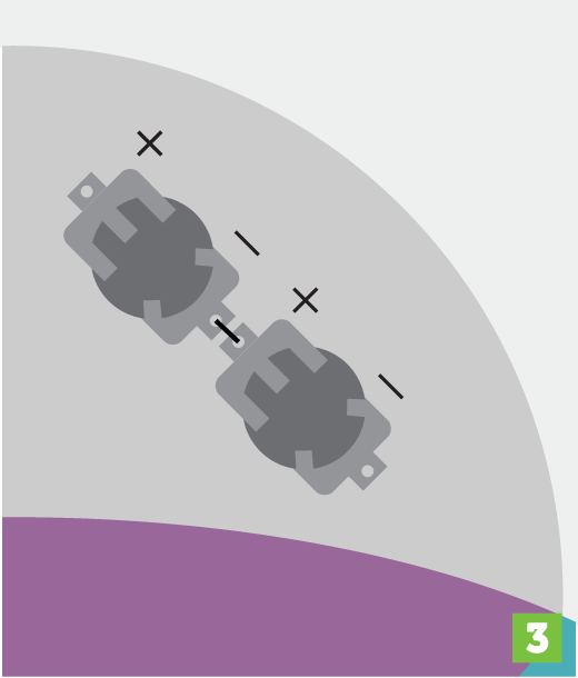
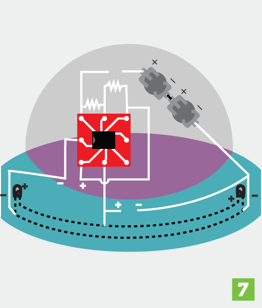
- On the back of your felt, glue the two battery holders in a series. Make sure that the positive and negative sides are pointing in the correct directions.
- Using conductive thread, connect the two battery holders together in the middle.
- Figure out where you want to put your LEDs and buzzer. Mark the positive and negative holes for your LEDs.
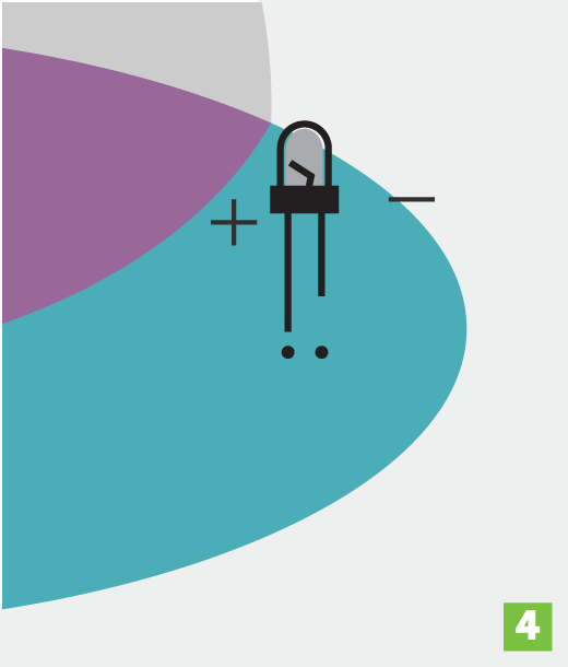
- Poke the legs of the LEDs and the buzzer through the felt.

- Using conductive thread, connect the positive legs of the LEDs to each other. Do the same with the negative legs.
- Sketch the circuit diagram on the backside of the project with a chalk pen. Mark the positions of the positive and negative legs for the capacitor between pins 1 and 2 on the 555 timer. Also mark the positive and negative legs for the buzzer.
- Carefully start to sew your circuit with conductive thread.
As you begin each thread, double-check the circuit diagram in Figure 8-5 to make sure that you are connecting the components properly.
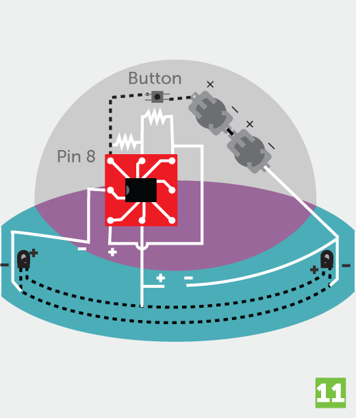
- Start by connecting pin 8 on the 555 timer to one of the legs on a push button. These buttons have four small legs. You can use any two that are diagonal from each other.
- Use needle-nose pliers to bend the legs into hooks so that you can sew to them.
- Finish attaching the button by connecting the diagonal leg to the positive side of the battery.
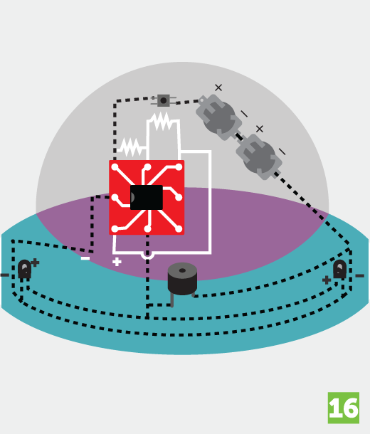
- Now add the buzzer. The buzzer has two legs, the longer of which is the positive leg. You’ll have to use needle-nose pliers to carefully bend the buzzer legs into hooks so that you can sew to them.
- Connect the positive leg of the buzzer to pin 3 on the 555 timer. Also connect pin 3 on the 555 timer to the positive legs on your LEDs.
- Connect the negative (shorter) leg of the buzzer to the negative legs of the LEDs.
- Connect the LED’s negative legs to the battery holder’s negative pole.
- Then connect the negative legs of the LEDs to pin 1 on the 555 timer.
- Add the two resistors to your circuit. Connect pins 6 and 7 on the 555 timer through a 10k Ω resistor and connect pins 7 and 8 through a 200 Ω resistor.

- Add the capacitor to your circuit. Connect the positive (longer) leg of the capacitor to pin 2 on the 555 timer. Then connect the negative (shorter) leg of the capacitor to pin 1 on the 555 timer.
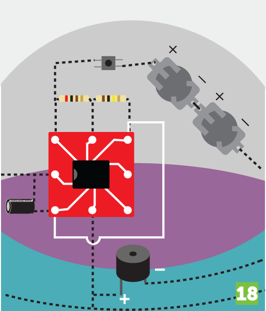
- Finally, connect pins 2 and 6 on the 555 timer. To do so, you are going to have to jump over the thread that is connected to pin 3. The bump in the illustration indicates that the two threads do not touch. Be very careful to avoid touching these two threads together. This would cause a short circuit. Make sure that the two threads cross on opposite sides of the felt.
- Once you’re done connecting the pins, double-check that all your parts are connected and in the right places by carefully comparing the circuit diagram in Figure 8-5 and your circuit, which should look similar to this illustration.
Start with pin 1 on the 555 timer. Make sure it is connected to all of the correct components and that the components are facing in the correct directions. Then move on to pin 2 and do the same thing. Repeat this process for all eight pins on the 555 timer. Note that pins 4 and 5 are not connected to anything. That is okay. We are not using those pins in this circuit.
- Finally, insert the batteries in the battery holders. If everything is connected properly, when you hold down the push button, you should see the LEDs flashing and hear a beeping sound!

Figure 8-8 and 8-9 show both sides of the completed project.
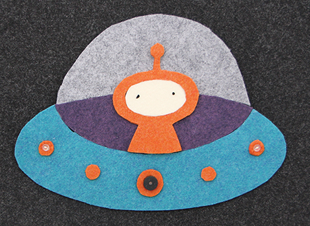
Figure 8-8: The finished UFO project
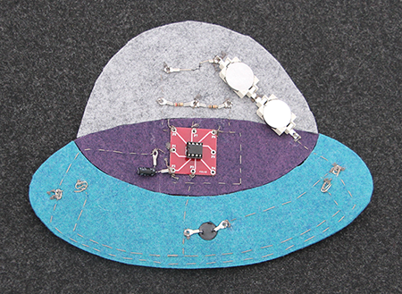
Figure 8-9: The finished UFO circuit
 Explore
The 555 timer is a popular chip for electronics enthusiasts because it is inexpensive, easy, and safe to use. You can make a lot of different projects with this chip.
Figures 8-10 and 8-11 show another idea for a project that uses a 555 timer.

Figure 8-10: This Christmas stocking has twinkling lights on a tree and snowman. You could also add this circuit to ornaments for your tree.
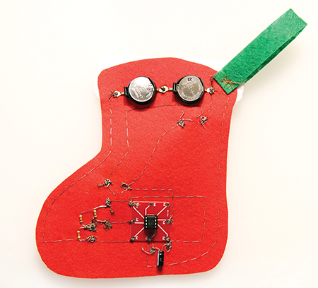
Figure 8-11: The 555 timer circuit on the back of the stocking
Figures 8-12 and 8-13 show a police car that I made that makes a beeping sound and has some flickering lights. I found that if the buzzer is too loud, I could cover it with some tape to dampen the sound.
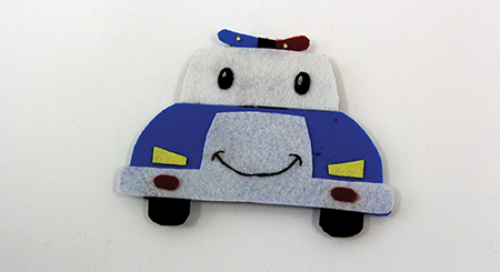
Figure 8-12: A friendly looking police car
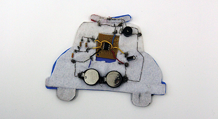
Figure 8-13: The circuit on the back of the police car
Prototyping Circuit Boards
Now that you’ve seen some project ideas, are you curious about how you can make your own circuit boards like the breakout board for the 555 timer? You can prototype your own circuit boards using something called a breadboard. A breadboard like the one in Figure 8-14 allows you to quickly and easily connect electronic components together to test your circuit.

Figure 8-14: A breadboard
Once you are sure that your circuit is working with the breadboard, you can design your circuit on a computer using a circuit design program like Eagle, Fritzing, or 123D Circuits. Both Fritzing and 123D Circuits allow you to order circuit boards directly from their programs, or you can send your circuit designs to a company like OSH Park that prints and mails circuit boards. Or if you’re even more adventurous, you can make your own circuits using a chemical etching process. To learn more about this process, check out this tutorial: http://makezine.com/projects/pcb-etching-using-toner-transfer-method.
The Tales of Grimm Dollhouse
Figures 8-15–8-17 show pictures of a school project for which I made my own circuit boards. This dollhouse has motorized puppets in each room. By turning the pages in a book, the reader controls the puppets and causes them to act out scenes from different fairy tales.
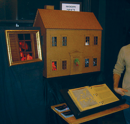
Figure 8-15: The tales of Grimm dollhouse
Figure 8-16 shows the custom-made circuit board I designed for the dollhouse. All of these wires are connected to the sensors on the pages of the book and different motors control the different puppets.
Figure 8-17 shows the custom circuit board I designed for this project.
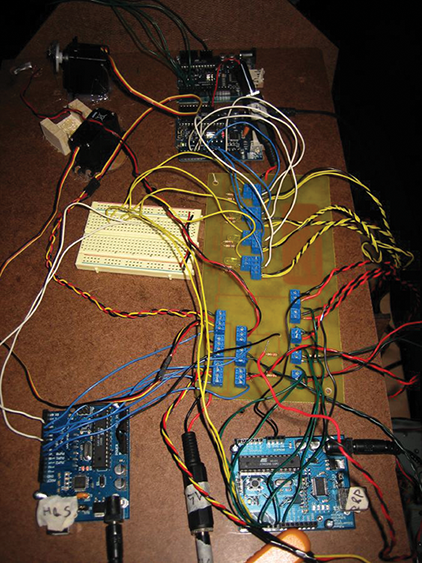
Figure 8-16: The complicated circuit for the dollhouse project

Figure 8-17: The design for the custom circuit board
What’s Next?
Wow! Now that you’ve learned how to use the 555 timer to make LEDs blink and a capacitor to store electricity, the next chapter is going to free you from batteries! You will use a solar panel and a super capacitor to collect, store, and use the energy from the sun!