

Photograph by Sam Murphy
KINETIC REMOTE CONTROL
SHAKE THE BATTERIES OUT OF THE PICTURE FOREVER WITH THIS MUSCLE-POWERED INFRARED REMOTE CONTROL.
A TV remote is one of the most commonly used electronic gadgets. We use it without even thinking about it — that is, until the batteries quit.
TV remotes use infrared light for communication with the TV set. Every infrared remote uses AA or AAA batteries to power an infrared LED, controlled by an electronic circuit that beams commands according to the buttons that you press.
This electronic circuit is a very low-power device. Nonetheless, every so often the batteries get drained, usually right when you need them most. And what happens to the used batteries? Perhaps you send them to your local battery recycling plant, or maybe they end up in your town’s landfill, polluting the environment. It would be very nice if we could use our remote control devices without any batteries at all!
It turns out that it’s easy to bag the batteries, as long as you’re willing to put in a little manual effort. How about simply moving your hand back and forth a few times? This motion represents kinetic energy that can be converted into electrical energy, sufficient to power any remote control.
Set up: p.111 Make it: p.112 Use it: p.115
Dhananjay V. Gadre is an assistant professor with the Electronics and Communication Engineering Division, Netaji Subhas Institute of Technology, New Delhi. Gadre likes to build electronic contraptions for work and for joy. He takes pride in not being associated with any national or international professional cartel, society, or association.
ZAP THE BATTERIES WITH A FARADAY KINETIC GENERATOR

Illustration by Pars/e Design
Infrared remote control devices are available for almost every entertainment gadget at home, be it a TV, DVD player, or music system. Remotes come in all shapes, sizes, and features, including universal remotes that can be taught or programmed to control any given piece of electronic equipment.
Whatever the type, every infrared remote consists of a power source in the form of AA or AAA batteries, an infrared LED, and a set of buttons connected to an electronic circuit that beams a code sequence corresponding to the key that you press.
Unlike most other electronic gadgets, an infrared remote has no On/Off switch. The remote is always on, consuming very little power when in a dormant state. When a button is pressed, the remote goes into an active state, transmits the control code, and then goes dormant again.
This project shows how to retrofit your regular remote control device for battery-free operation, forever. The idea is not so much to save on recurring battery costs, but to remove batteries from the system altogether and, in your own small way, contribute to a greener planet.
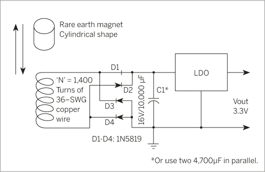
The voltage required by the remote control device is generated using a DIY kinetic generator (shown above) that converts mechanical power to electrical power, based on Faraday’s principle. The device consists of a hollow tube of plastic or wood, with a cylindrical magnet sealed inside the tube, and 1,400 turns of enameled copper wire wound around the outer surface of the tube.
When the tube is shaken, the magnet travels the length of the tube back and forth. This leads to a change of magnetic field as seen by the wire, and generates an EMF (electromagnetic force) that is proportional to the number of turns and the rate at which the magnetic field is changed. Thus, if you shake vigorously rather than gently, a larger EMF is generated. You can use this principle to easily generate operating voltage for any infrared remote control device.
SET UP.
Photography by Dhananjay V. Gadre
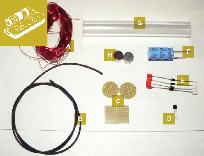
MATERIALS
[A] Enameled copper wire, 30 or 36 gauge, 65′ Enough to roll about 1,400 turns of wire. The gauge of the wire is not critical. I used 36 gauge, but any other, preferably smaller gauge (larger diameter), can also be used.
[B] 1mm-diameter heat-shrink tubing to insulate the copper wire going into the remote control. I used Digikey part #A364B-4-ND (digikey.com).
[C] Perfboard I used RadioShack part #276-1394.
[D] Voltage regulator LP2950-3.3 This is a 3.3V output, low dropout voltage regulator. I used Digikey part #LP2950ACZ-3.3-ND. A 3V output version can also be used.
[E] 1N5819 Schottky diodes (4) You can also use 1N5817; I used Digikey part #1N5817-TPCT-ND.
[F] 4700µF/16V electrolytic capacitors (2) Digikey part #565-1538-ND. Two of these capacitors are used in parallel.
[G] Acrylic tube 6" long, 7/8" OD, 5/8" ID I used McMaster-Carr part #8532K17 (mcmaster.com).
[H] Rare earth magnets (4) cylindrical shape, 1T strength, ½" diameter, Amazing Magnets part #D375D. amazingmagnets.com
[NOT SHOWN]
Masking tape
A complete kit with all the parts is also available at dvgadre.com/makeremote.
TOOLS
[NOT SHOWN]
Wire snipper
Digital multimeter
Baby hacksaw
TV remote control
Flat file
Soldering iron
Solder
Hot glue gun
Lathe (optional) to machine the acrylic tube. You can do without.
Coil-winding machine (optional) I used one to wind the wire onto the machined section of the acrylic tube. You can also use a power drill (and a friend to help).
MAKE IT.

BUILD YOUR NO-BATTERY REMOTE
Time: 2 Hours Complexity: Easy
START ≫
1. BUILD THE FARADAY GENERATOR
The system consists of 4 main components:
1. Infrared remote control device
2. Faraday voltage generator
3. Charge storage component
4. Voltage regulator
Shown here is the schematic of the Faraday voltage generator, the charge storage capacitor (capacitor C1 consisting of two 4700µF/16V capacitors in parallel), and the voltage regulator circuit based on a low dropout (LDO) regulator.
1a. Groove the tube (optional). I chose a 7/8" diameter Perspex acrylic tube with 5/8" internal diameter. The length of the tube is approximately 6". You’ll need to machine out a 1.5mm-deep groove into the tube, along about 2" of the tube’s length. The groove is where you’ll wrap the wire. If you don’t have access to a lathe with which to cut a groove, the wire can be wound directly onto the plain acrylic tubing. Just use plenty of masking tape to ensure the wire doesn’t unwind.

1b. Wind the wire. Fill the groove with 1,400 turns of 36 SWG enameled copper wire. If you have a coil-winding machine, it will be a lot easier. If not, you can improvise with a power drill and a helper: use the drill to slowly rotate the tube while a friend, wearing work gloves, feeds the wire to you. Leave about 6" of wire free on each end. When you’re done, cover the wire coil with masking tape, and use 1mm-diameter heat-shrink tubing to cover the 2 free ends of the wire. If you didn’t groove the tube, just wind the copper wire directly onto the plain acrylic tube. Be sure to use plenty of masking tape to ensure that the wire doesn’t unwind.
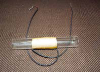
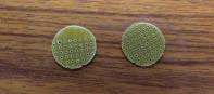
1c. Place the magnets inside the Faraday generator tube, stacking all 4 to make 1 big magnet. Using a hot glue gun, seal the ends with 2 pieces of perfboard, cut and filed in circular shape. To make it more permanent, use a 2-part epoxy.
2. PREPARE THE TV REMOTE
2a. Remove the batteries from the remote control (forever!) and file down the entire battery compartment to remove all extrusions, as shown.
Also file a notch in the side of the battery compartment and the compartment cover, so you can run the wires from the Faraday generator inside.
NOTE: You’ll need to take the guts of the remote out. Just set them aside.
2b. Assemble the components from the circuit diagram (capacitors, diodes, and LDO voltage regulator) on a perfboard as shown here. You can test the continuity with a multimeter.
2c. Solder the output of the voltage regulator circuit onto 2 hookup wires (extreme right in the photograph) on one end of the perfboard. You’ll eventually solder these hookup wires to the battery terminals of the remote control.
2d. Connect the Faraday generator. First solder 2 hookup wires in the middle of the perfboard to the input of the bridge rectifier (cathodes of diodes D3 and D4, respectively, in the circuit diagram). Then solder the wires from the Faraday generator to these hookup wires.
2e. Reassemble the TV remote, and fit the circuit board inside the battery compartment as shown.

2f. On the remote control’s original circuit board, cut down the battery terminals so that they can be soldered to the voltage regulator circuit board. Solder them to your voltage regulator output wires.

2g. Tie the Faraday generator temporarily to the TV remote body using cable ties, and shoot more hot glue between the remote and the Faraday tube. If you want to glue them more permanently, use a 2-part epoxy such as Araldite or J-B Weld’s J-B Kwik epoxy. Now you’re ready to shake!
FINISH X
NOW GO USE IT »
USE IT.

SHAKE AND SURF
»To use the device, just shake the remote control back and forth a few times. For my prototype, I shake it about 3–4 times to charge the capacitor, and then I can use it for about 20 key presses.
My first and only “harmonic” (aka my son, Chaitanya) is seen here shaking the battery-less remote to use it to watch his favorite TV program.
If you modify your remote using these instructions, I congratulate you for your effort in preserving the environment. I would love to see the photographs of your completed device! Feel free to mail them to me at [email protected] and post them to the MAKE Flickr pool.
Acknowledgements
I would like to thank Satyaprakash for his ideas and for helping me in this project. I also thank Edward Baafi for his efforts in sourcing many of the components used in this project. I published a different design for a kinetic generator in “Power Generator for Portable Applications,” Circuit Cellar magazine, October 2006.