
Photography by Edwin Wise
“SOLAR JOULE” BRACELET
 Solar-cell links are cleverly boosted to drive an LED jewel.
My wife fell in love with Alice Planas and Hatti Lim’s glowing bracelet project from CRAFT magazne (Volume 06, page 123, “Solar Jewelry”), so of course we had to make one. I built the circuit and she did the fabric. It came out nicely, but I felt it could be improved, so I decided to combine the solar jewelry idea with a Joule Thief circuit that would make the LED glow brighter. The result is the Solar Joule!
Joule Thief Theory
The Joule Thief is a small circuit that converts low voltages, like from dead batteries, into an oscillating voltage with peaks high enough to be useful. There are many versions online (see makezine.com/19/diycircuits_solarjoule).
The heart of the circuit is a pair of inductor coils wound together into a transformer or choke. When current runs into one coil, it’s resisted as it builds up a magnetic field. This field pushes current through the other coil, going in the opposite direction. In the Joule Thief, one coil provides the kick of voltage to light up the LED, and the other generates feedback that drives a transistor into oscillations.
Here’s how the feedback works (Figure A, left side, following page). When you first connect power to the circuit, the transistor is off, there is no magnetic field in the choke, and there’s not enough power to turn on the LED. Some power leaks through the resistor into the transistor’s base, turning it on a little bit. This lets a bit of current run backward through inductor coil 1-2 of the choke, creating an expanding magnetic field. As a result, current is run through inductor 4-3, which turns the transistor on even more. This positive feedback loop continues until the transistor is completely activated.
Once the transistor is done opening, the current through 1-2 stops increasing, so the magnetic field stops expanding and stops pushing the current through 4-3. This causes the transistor to close a bit, which reverses the feedback loop. Current reverses through 4-3, closing the transistor more and blocking current flow through 1-2. When the transistor shuts off, the inductor’s magnetic field winds down and unloads a blob of charge, which then runs through the LED to light it. The current is quickly exhausted, and we are once again at the starting state.
MATERIALS
All values are approximate and not particularly critical
For the solar collector:
Wire, 22-gauge solid I used insulated wire and stripped the insulation.
PIN photodiodes (10 or more) Mouser Electronics part #782-BPW34, mouser.com
Supercapacitor, 0.22F Mouser part #598-EDLSD224V5R5C
Schottky signal diode Mouser #625-SB330-E3
Nice fabric or other bracelet material for mounting
For the Joule Thief circuit:
Common-mode choke, 51μH Mouser #875-CC2824E513R-10
NPN transistor Mouser #512-BC549
Resistor, 1kΩ to 3kΩ, 1W such as Mouser #299-1K/AP-RC
Capacitor, 0.01μF axial Mouser #80-C114C103K5R
LED, any size or type such as Mouser #604-WP7113QBC/D
TOOLS
Wire cutters
Small bolt
Small pliers Round-tipped are nice, for making loops.
Soldering iron and solder
Liquid flux (optional)
Third-hand vise (optional)
Voltmeter and/or oscilloscope (optional)
The capacitor between the resistor and the choke provides a little “spring” to the feedback action, buffering some of the voltage changes across inductor 4-3.
Build the Solar Battery
First I built the solar battery, which is a series of PIN diodes bridged by a supercapacitor that stores the energy they collect (Figure A, right side). The photodiodes also act as links in a chain bracelet, and I connected them with loops of wire to provide some spring and make it easy to sew them onto fabric.
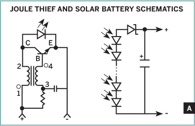
Fig. A: Dots indicate like-voltages on the choke.
To make the loops, wind solid wire around a small bolt, cut it at every other turn, and re-bend the ends of each loop into small solderable hooks (Figure B). Then solder 10 (or more) diodes in series, + to – (Figure C). The silver strip on each diode’s face indicates the + side. If you want to go crazy, make 2 strips of photodiodes and connect them in parallel, side by side (+ to + and – to –).
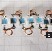
Fig. B: Loops of solid wire wound around bolt, cut, and bent.

Fig. C: Photodiodes soldered in series, connected by wire loops.
Solder the Schottky diode to the + end of the series, with its black stripe (the – end) pointing away from the photodiodes. The Schottky diode ensures that power flows into the capacitor when the photodiodes are in bright light, but won’t flow back out when they’re dark. Any diode will work here, but a Schottky diode consumes less voltage in the forward direction, saving more for the LED.
Solder in the supercapacitor, with its + side at the signal diode and its – side all the way at the other end of the PIN diodes. Finally, solder a wire to each end of the capacitor (Figure D), to connect to the Joule Thief later, and set the solar battery in the sun.
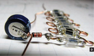
Fig. D: Solar battery with the Schottky diode and supercap soldered in.
Build the Joule Thief
Many versions of this project involve winding your own transformer, but I’m lazy, so I bought one. It’s a surface-mount (thus, very small) common-mode choke with a ferrite core. The white dot on top indicates pin 1, and the pins are numbered clockwise.
Start by bending the emitter pin on the NPN transistor 90° away from the flat side. Then bend the collector and base pins so that you can solder them to pins 2 and 4 of the choke, respectively (Figure E). (Note where pins 1 and 4 go when you turn the choke upside down.)

Fig. E: Solder the transistor collector (C) and base (B) to pins 2 and 4 of the transformer.
Position the resistor across the base pin, bend its leads down the sides of the choke, and solder it between pins 1 and 3. Trim the pin 3 lead, but leave the pin 1 lead long to connect to the battery’s positive (+) terminal (Figure F). Any resistor from 1K to 3K should work. A larger one will be more efficient, but I happened to have a 1K resistor on hand.
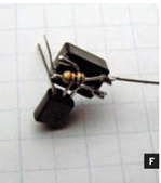
Fig. F: Solder the resistor between pins 1 and 3 of the transformer.
Flip the assembly over and solder the axial capacitor between pin 3 (or the resistor lead connected to it) and the transistor’s emitter pin (Figure G). This capacitor isn’t required for the circuit to work, but it increases efficiency. An axial capacitor fits better here than a regular disc-shaped cap would, so it makes the circuit more compact.
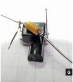
Fig. G: Solder the capacitor between the transistor emitter (E) and pin 3 of the transformer.
Now let’s set the LED jewel. Bend out the LED’s shorter cathode lead (–). Solder the anode lead (+) to the choke’s pin 2 or transistor’s collector. Solder the cathode to the transistor’s emitter, which should be conveniently poking up. Trim the LED’s anode but leave the cathode lead long (Figure H).
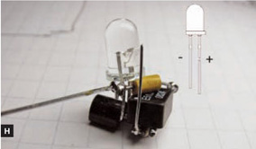
Fig. H: Solder the LED “jewel” between the transistor’s collector and its emitter.
Solar Jewel + Joule Thief
Using wires or alligator clips, wire the Joule Thief and the solar battery together, + to + and − to −. The LED should glow! If you watch the LED’s positive lead with an oscilloscope, you should see it pulsing up to the LED’s forward voltage at 300kHz to 500kHz. Since that’s too fast for your eyes to discern, it looks like a steady glow.
If it doesn’t light, use a voltmeter to confirm that your solar battery has a charge. It doesn’t take much; half a volt is plenty. But it may require many minutes of bright sunshine to charge the cap the first time. If you have voltage but no glow, confirm that the diodes, capacitors, and the choke’s inductors are all oriented correctly.
I’m ignoring the final part of the project here: a crafty mounting that you provide for the other 2 parts. That’s up to your imagination.
![]() See makezine.com/19/diycircuits_solarjoule for schematics and a link to the original Joule Thief circuit.
See makezine.com/19/diycircuits_solarjoule for schematics and a link to the original Joule Thief circuit.
Edwin Wise (simreal.com) is a software engineer with 25 years’ experience. He develops software during the day and explores the edges of mad science at night.
BURNOUT SOUNDS
 Guitar effects from old compact fluorescent light bulbs.
When compact fluorescent lamps (CFLs) burn out, don’t throw them out! Carefully pry apart the base with a flathead screwdriver, and you’ll find a tiny circuit board stuffed with useful components. Then you can recycle just the bulb (be careful not to break it). Removing the bulb is the first thing they do at the recycler’s anyway.
I’ve opened up a few different brands, and the contents are all pretty much the same. A typical inventory includes 2 transistors, four 1N4005 diodes, assorted ceramic capacitors and resistors, a 10μF electrolytic capacitor, and a small coil transformer.
I don’t bother salvaging the resistors, but I use the film caps, transistors, and diodes to make guitar effects boxes. Fuzzes, boosts, and buffers — oh my!
Here are some CFL-based effects that I’ve concocted and had fun with. You can find the schematic diagrams at makezine.com/19/diycircuits_cflreuse, along with links to other CFL component projects and DIY guitar effects resources.
» Fluorescent Fuzz and Shining Sixties Fuzz These impart a 60s or 70s rock/psychedelic sound.
» 13 Watt Overdrive This adds some 70s rock “crunch” to your tone.
» Light Ranger This treble booster is great for making your guitar solos stand out and cut through the mix.
» Bulb Booster This makes your signal louder, pushes your amp harder, and generally makes everything sound better.
The schematics online show the core circuits. For a volume control, add a potentiometer between the circuit’s output and the output jack on the box, with the third contact going to ground. Using a stereo jack for input lets you either activate the effect circuit or bypass it, depending on whether the 3PDT step switch connects to the right or left channel.
For all of these, you solder the circuits onto a small piece of perf board, then add leads to connect out to the battery snap and input/output jacks. To secure the circuit board inside the box, I use velcro tape.
For inspiration and help with my various DIY audio projects, I give credit to diystompboxes.com, muzique.com, buildyourownclone.com/board, and geofex.com. They all host great communities with great people.

Photograph by Ed Troxell
MATERIALS AND TOOLS
Old CFL bulb
Resistors Values vary for different effects; see schematics online at makezine.com/19/diycircuits_cflreuse.
Potentiometer, 100kΩ
Small perf board
Hookup wire
1/4” audio jacks, 1 stereo and 1 mono
3PDT (triple pole, double throw) step switch available from Pedal Parts Plus (pedalpartsplus.com), Small Bear Electronics (smallbearelec.com), or diystompboxes.com. You can also use a DPDT (double pole, double throw) switch, but that’s suboptimal.
Case available from Pedal Parts Plus or Small Bear Electronics. Or you can use any small, strong box (like a circuit junction box), or make your own.
Velcro tape
Flathead screwdriver
Soldering materials
![]() Visit makezine.com/19/diycircuits_cflreuse for schematics, resources, and links to more CFL component projects.
Visit makezine.com/19/diycircuits_cflreuse for schematics, resources, and links to more CFL component projects.
Andrew Carrell caught the electronics bug from his Dad and currently makes music (and sometimes noise) in Austin, Texas.

Photography by Ed Troxell
BREAKING AND ENTERING
 Open and repair a damaged proximity swipe card.
It all started one day at work. I had used my swipe card to get through the front doors, and without thinking too much, I put it in my back pocket. Later that day I sat down — crunch! The card had cracked from side to side. I wrapped it in tape to hold it together, and it still worked for two weeks, but then something in it failed. I tailgated people in and out of the building that day.
I had paid my company a $100 deposit on that pass card, and that night I decided I wasn’t going to give it up by asking HR for a new one. I was determined to fix it myself.
A bit of research showed that these pass cards are often called “proximity cards,” and operate in a manner similar to the tiny RFID tags found inside the new U.S. passports and even pet dogs. (See “How Does It Work?” on the following page for a basic explanation of their operation.)
Bending the card slightly to widen the crack revealed a coil of fine copper wire inside, and when I dismantled the card completely, I was surprised to find that its plastic shell contained not only a coil but also a small integrated circuit (IC) on a printed circuit board (PCB). Even more surprisingly, it had no battery!
I carefully removed some of the outside shell to reveal more (Figure A, following page), and then exposed the coil and PCB completely.
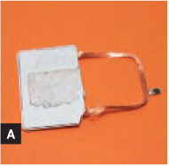
Fig. A: Removing part of the shell reveals the tiny circuit board and damaged coil.
With the aid of a jeweler’s loupe, I could see that the wire coil had broken —in many places, unfortunately. It would have been a major job just to identify the correct wires to solder back together, let alone actually doing it! Plan B was to wind my own coil, but back in the depths of my mind were the makings of Plan C: replacing the coil with one from another card.
After 20 minutes pawing through one of my junk boxes in the attic, I found an old pass card from a previous employer. It carried a different code, so it wouldn’t work at my current office, but its coil was intact. What’s more, the heat in the attic had dried out the glue — the card practically fell apart in my hands (Figure B). Plan C was the way to go!

Fig. B: The old, donor card. Its coil is intact, but its chip contains the wrong code.
I used a sharp craft knife to pry away the old glue that held the coil and mini PCB to the plastic shell. I took great care, as I couldn’t afford any breakages. After 10 minutes, the salvaged coil was free.
I unsoldered the donor coil from its original PCB using a fine-tipped soldering iron, holding the PCB with a pair of locking tweezers. This was easy, as I didn’t have to worry about overheating and possibly damaging the old IC. After removing the coil, I tested its continuity with a multimeter. Success! The coil was intact.
The tricky part was attaching the new PCB. This time, I had to be careful to keep the iron on the joint for as little time as possible, since the PCB was small and could quickly overheat, killing it forever.
Things went well, though, and because the ends of the coil were already tinned where I removed them from the old board, the joints were easy to make. The coil from my old card was now connected to the mini PCB from my new card.
Now it was time to look at the housing. My old card’s shell was filled with dried-out glue and covered with ground-in grime. Fifteen minutes later the case was clean, thanks to some isopropyl alcohol, a soft cotton rag, and a bit of elbow grease.
The last step was to position the coil and PCB in the old case and hold it in place with a few drops of glue (Figure C). The card’s thin plastic backing had suffered from the cleaning process, so I elected to replace it with a piece of clear, self-adhesive book film trimmed in place with a craft knife. (White book film would have been fine, but with clear film, the card made a great talking point with my co-workers.) The results looked good, but the acid test would have to wait until the next morning at work.
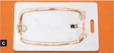
Fig. C: The good chip soldered to the donor coil, in its case.
At 8:36 a.m. I waltzed up to the front door and waved my pass at the security panel. “Click!” went the door. “Woo hoo!” I shouted. The guys in HR couldn’t understand why I was smiling so much that day.
RFID Tag: How Does It Work?
There’s a lot of misinformation out there about how RFID works. Here’s a typical explanation:
The reading unit (attached to the door) transmits radio energy. The card receives this energy, converts it to electrical energy, and then uses it to transmit its serial number back to the reading unit, which recognizes the card and opens the door.
While this is neat and simple, it’s also wrong. Yes, the card’s coil antenna absorbs the RF energy, and this is used to power the chip, but technically speaking, the card doesn’t transmit anything at all!
Without going into the gory details (look up “load modulation” if you want them), you can better explain RFID with the following analogy:
Let’s say you’re out on a boat, and you want to use a mirror to send information to a lighthouse. You can encode it in a binary format and then transmit one bit each time the lighthouse beam sweeps by, where reflect means 1 and not reflect means 0.
Security pass cards use the same principle, but instead of one sweep every 10 seconds or so, the reader transmits at 125kHz. The card’s chip communicates its data by selectively shorting out its coil over successive cycles of the 125kHz transmission. A shorted coil doesn’t absorb any of the RF energy, while a non-shorted coil does, so the reader then distinguishes 1 from 0 by measuring the peak voltage on its antenna to see if it’s high or low. In this way, the card communicates its 24-bit serial number, along with synchronizing and checksum data.
Graham Cattley has been obsessed by electronics since he was 4, and has published numerous technical electronics articles in Australia over the past 15 years.