
PULSE SENSOR
A wearable device to give your projects a live heartbeat.
Poets and artists have always sought to bare their hearts to the world, and today heartbeat monitoring is essential to physicians, athletes, and many others. The beating of our hearts carries evocative power, symbolic meaning, musicality, and practical utility, so it’s not surprising that many DIYers try to incorporate it into their projects.
Matt Richardson
Colleagues at Parsons The New School for Design, Yury Gitman is a toy inventor and product designer who teaches Physical Computing and Toy Design, and Joel Murphy is an artist and engineer who teaches Physical Computing and Cybernetics.
THE MOST COMFORTABLE AND WEARABLE technique for capturing heartbeats is to use an optical pulse sensor (Figure A). These devices shine light through the skin and then analyze the light reflected back — like shining a flashlight through your fingers to see your pulse. With each pump of the heart, capillary tissue fills with blood, increasing the tissue’s volume and decreasing its reflectivity. Track the level of the reflected light with an optical sensor, and you can derive the pulse. (Oxygenated blood entering capillaries is more reflective at some wavelengths than the exiting “used” blood, but heartbeats still lower the overall reflectivity.)
Yury Gitman
Optical pulse sensors are easy to understand in theory, but in practice, it’s hard to make one that works. As professors, year after year, we see our students attempt to follow published guides and either fail to get anything operational, or else get poor results. The circuit designs are typically too complex for novices; it’s difficult building them to hold up to the physical stresses of being worn out in the world; and it’s tough to program a microcontroller to extract a heartbeat from the raw and possibly noisy sensor data.
We decided to design a pulse sensor for small-scale manufacture that would be easy to use in our own creative projects, and that we could also make available to students, makers, game developers, mobile developers, artists, athletic trainers, and others. We knew about mobile apps like Azumio’s Instant Heart Rate, which uses a smartphone’s illuminator and ambient light sensor to read a pulse, but we wanted a simple, dedicated sensor that could be easily wearable, good for teaching, and “plug and play” into Arduino and other microcontrollers.
HARDWARE AND DESIGN
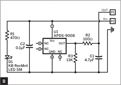
After months of experimentation with different optical sensors and LEDs, we hit on a good combination: a green LED from Kingbright (AM2520ZGC09) with a peak wavelength of 515nm, and a photosensor from Avago (APDS-9008) with peak sensitivity at 565nm. The sensor is designed for adjusting the LCD brightness of phones and laptops against ambient light, and it’s only available as a surface-mount component. But it has its own integrated amplifier, which simplified the circuit we needed. Output from these sensors can be noisy, so we added a 100Ω resistor and a 4.7μF capacitor to act as a low-pass filter (Figure B). R3 sets the output sensitivity, and R1 sets the LED brightness. The other capacitor (C2) helps smooth the power supply.
Damien Scogin (B)
MATERIALS
Pulse Sensor Kit pulsesensor.com, $20
Arduino-based microcontroller To make the Beating Heart Headband, use the MintDuino kit, listed below.
For the Beating Heart Headband, add:
Open Heart Kit MKJR1 from Maker Shed (makershed.com)
Mintronics MintDuino kit MSTIN3 from Maker Shed
Perf board, with at least 15×20 holes 276-149A from RadioShack (radioshack.com)
LilyPad LiPower power board DEV-08786 from Sparkfun Electronics (sparkfun.com)
Polymer lithium-ion battery, 3.7V, 850mAh, with JST connector PRT-00341 from SparkFun
Wire, insulated, 20–22 gauge
Header, male, right-angle, 3-pin
Fabric trim, at least 1¾" wide or other good material for a headband
Fabric or ribbon for headband lining
Snaps, small (4)
Thread
Cord elastic
TOOLS
Hot glue gun and glue
FTDI Friend and USB cable or FTDI-USB cable for programming ATmega328P chip in MintDuino kit
Computer with internet connection and USB port
For the Beating Heart Headband, add:
Soldering equipment
Panavise
Tin snips, razor saw or other way to cut perf board
File
Wire cutters and strippers
Fabric shears
Sewing machine
Needle and pins
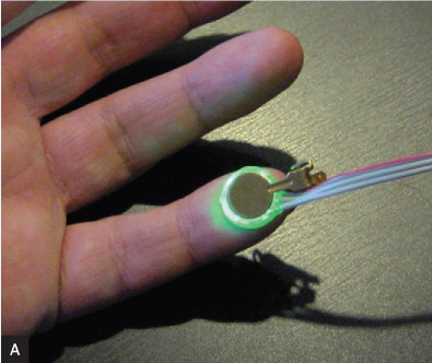
Our final circuit uses just 7 components, and since they’re all tiny surface-mount packages, the whole thing fits onto a ½" round PCB. The LED faces down into the board and the photosensor is surface-mount soldered right side up on the front, which lets them sit on the backs of flat panels. Fortunately for our needs, this also means that they send and receive light through holes drilled in the board, which isolates it against contamination from ambient light and lets the board lay flat and comfortably against the skin (Figure C).

Since production includes drilling holes in the board, we decided to add “buttonholes” around the outside of the sensor, to let users easily sew or attach it to various garments and fashion accessories. We ended up with a ½" green glowing disk that clips to an earlobe and resembles a prop from a science fiction movie. When we realized we had inadvertently made jewelry for a future race of human-machine cyborgs, we knew we were done.
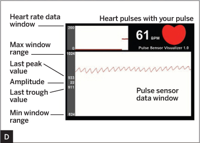
On the software side, we wrote Arduino code that takes analog input from the Pulse Sensor, cleans up the signal, and outputs beat pulses to 2 output pins — a simple square wave to pin 13 and a pulse-width-modulation (PWM) fading pulse to pin 11 — for a more lifelike LED effect. The Arduino also continuously outputs current peak, trough, and beats-per-minute (BPM) values for the sensed waveform to its serial interface (ASCII via pins 0 and 1). Meanwhile, we also wrote a Pulse Sensor Visualizer in Processing that you can run on a computer to read serial data from the Pulse Sensor and graph it on-screen.
1. GRAPH YOUR PULSE
The best way to get started is to graph your pulse using the visualizer program. First, attach the clear sticker to the Pulse Sensor’s face (logo side) to protect it from finger oils and sweat which could create a noisy signal.
Connect the sensor’s standard 3-wire connector end to an Arduino board so the red wire runs to power (the Pulse Sensor works with either 5V or 3.3V DC), the black wire runs to ground (GND), and the purple wire (signal) runs to the Arduino’s analog pin 5, which is set in the code as the PulseSensor pin. You can make the connections using jumper wires (Figure F) or a 3-pin header in a breadboard.

Before you attach the Pulse Sensor to the ear clip or velcro dot, get it up and running so you can find the best place on your body to get a good signal. If you don’t already have them, download the Arduino and Processing programming environments at arduino.cc and processing.org, then download the latest Pulse Sensor software at pulsesensor.com.
Connect the Arduino to your computer and configure the Arduino IDE under the Tools menu for your specific board and the COM port it’s plugged into. Open the A_PulseSensor_XX sketch (XX is the version number) and click Verify and then Upload to transfer it to the Arduino. You should see pin 13 blink in time with your heartbeat when you hold the sensor on your fingertip with the right pressure. There’s a “sweet spot”: too hard, and you squeeze the blood out of your fingertip; too loose, and you admit noise from movement and ambient light.
Play around and try different parts and pressures. Note that the Pulse Sensor has a warm-up period of up to 10 seconds, during which its signal is smaller. If you see an intermittent blink, or no blink, you might be a zombie or a robot.
Start up Processing on your computer, and run the P_PulseSensor_XX sketch. You should see a window showing a reconstruction of the raw waveform at the bottom (Figure D). Top center shows the current detected heart rate, top left charts it over time, and the red heart at top right pulses to the beat. If not, try other spots on your body; for example, Yury gets a clear, reliable signal when the edge of the sensor PCB is at the bottom edge of his earlobe.
2. PREPARE TO WEAR
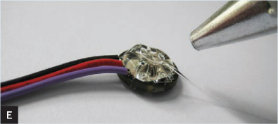
Once you’ve found a good spot to wear the sensor, encase the components on the back in a layer of hot glue to prevent short-circuits (Figure E). If you’ll wear the sensor on your finger, peel and attach one of the velcro dots over the hot glue, for attaching inside a velcro finger cuff. For wearing the sensor on your ear, press the back of the ear clip into the hot glue. The plastic body of the LED will prevent the metal clip from making any short circuits. If you make a mistake with hot glue, you can always reheat and rework it. You’re done!
We’ve made some great projects with our Pulse Sensor, including a pulse-blinking heart-shaped pillow. And with 2 sensors, it’s fun for a couple of people to try making their hearts beat in sync by controlling their breath or holding hands. Technology can get a bad rap for alienating people, but games with heartbeats bring people together.
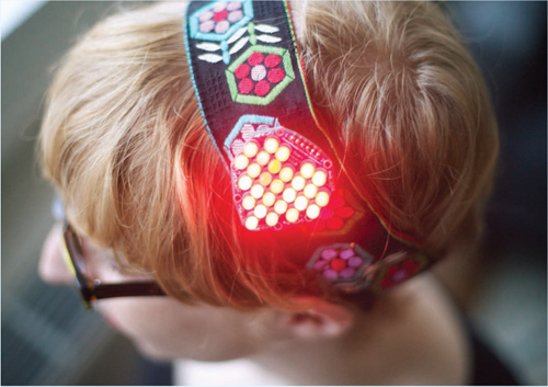
Our friends Becky Stern and Jimmie Rodgers recently made a cute LED beating heart headband using the sensor and Jimmies’ Open Heart kit. Learn how on the following page — take it away, Becky and Jimmie!
THE OPEN HEART LED KIT BEGS TO BE controlled by a Pulse Sensor, and a headband makes a great location since it has easy ear-lobe access. First assemble the Open Heart Kit using the straight 6-pin header.
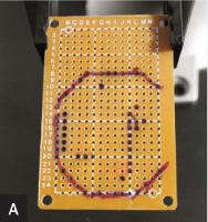
Refer to the MintDuino instructions to fit the ATmega328P chip and other components for an Arduino clone onto your perf board, cut to be smaller than the Open Heart. Mark the component locations, but don’t solder them in yet (Figure A). Run the programming header along an edge, for easy plugging in. Add a 3-pin right-angle header for the Pulse Sensor to connect to power, ground, and an analog input pin. Also mark a 6-pin row, positioned to plug into the Open Heart’s input header, to wire to 6 digital I/O pins.
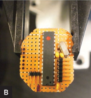
Cut the perf board to the same size as the Open Heart, file its edges, and solder on the Arduino components. Add V+ and GND wires, and connect the Pulse Sensor. Program the microcontroller (code is at the URL below), plug in the Open Heart, and test (Figure B).
Measure the circumference of your head, then cut 2 pieces of ribbon to that length. Line up the ribbons and use a zigzag stitch along 2" of the sides, tacking the ribbons together at the ends only. To make the headband stretchy, connect the ribbon tails by sewing them around a loop of cord elastic or a spare hair band. Adjust the amount of seam allowance so the headband fits snugly and comfortably (Figure C).

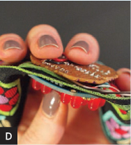
Decide where the Open Heart should go, and push its input pins through the fabric. Run the pins through their designated holes on the perf board Arduino, and solder into place, sandwiching the headband (Figure D).
Connect the power wires to the LiPower, and sew it into the headband near the heart (Figure E). Run the Pulse Sensor wires down the other side, and sew them in as far as needed for a good exit point near the ear (Figure F). The LiPo battery is small and light enough to not require sewing in. Finish sewing the lining and install snaps along one side to make a pouch for accessing the electronics. Switch on the LiPower, don the headband, and clip the sensor to your ear (Figure G)!


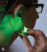
Jimmie Rodgers (A); Becky Stern (B–F); Matt Richardson (G)
As a variant, we thought it would be interesting to replace the red LEDs with infrared. That way, the heart’s blinking would not be visible to the human eye, but you could see it on camera. This would be a fun a device for a reality dating show, and any interested television producers are welcome to contact us. ![]()
![]() Code, circuit diagram, video, and more photos at makeprojects.com/project/n/1622.
Code, circuit diagram, video, and more photos at makeprojects.com/project/n/1622.
Becky Stern (sternlab.org) is senior video producer for MAKE. Jimmie Rodgers (jimmieprodgers.com) is an open source electronics maker and full-time nomad.