
DIY BLOOD
PRESSURE MONITOR
Make a blood pressure tester that’s tough, smart, and mobile.
High blood pressure, also called hypertension, is deadly: it can lead to heart failure, stroke, and kidney failure. One-third of Americans have it, and in the developing world it’s the leading killer of pregnant women due to lack of screening.
Existing blood pressure tests are painless but the equipment is flawed: it’s delicate and impractical in many settings, and it contains mercury, which is toxic when released into the environment. It’s also prone to human error, because it depends on a doctor listening to the patient’s pulse through a stethoscope.
So we came up with a DIY blood pressure monitor that’s better. It’s portable and battery-powered, making it great for areas with unreliable electricity. It’s solid-state, so it’s tough and reliable and doesn’t contain mercury. And it detects high blood pressure automatically, drastically reducing error.
Here’s how you can build one for less than $50 and test your blood pressure anytime.
OUR DIY BPM
Our Self-powered, Environmental, Affordable Blood Pressure Monitor (SEA-BPM, or seabump) is easy to use. An inflatable arm cuff contains an electronic pressure sensor that measures the air pressure inside the cuff. When the cuff is inflated sufficiently it completely occludes the artery. As the cuff is deflated blood starts to flow through the artery, and pressure on the arterial walls rises and falls with every heartbeat.
This causes oscillations of the cuff’s pressure that are detected by the sensor, and can be used to calculate both the systolic (maximum) and diastolic (minimum) blood pressures. This is known as the oscillometric blood pressure method (for details, see makezine.com/go/obpm). Our algorithm to calculate both pressures is implemented in C for programming onto a PIC microchip.
For energy efficiency in areas of the world without reliable electricity, our device uses NiCad batteries that are recharged using a hand crank generator. Fully charged, they power the device for about 50 hours. We also removed the delicate mechanical pressure meter from the device to reduce the size and weight and make it more robust. Since it’s automated, readings are more precise and not prone to human error. A reading takes less than 30 seconds.

Garry McLeod
MATERIALS
Circuit board, about 3"×4" RadioShack part #276-168, radioshack.com
DIP sockets: 8-pin (1), 14-pin (1), and 28-pin (1) such as Digi-Key parts #A24807-ND, A24808-ND, and 3M5480-ND, digikey.com
Voltage regulator IC, 8-pin Digi-Key #LT1121CN8-3.3#PBF-ND
Microcontroller, Microchip PIC18F2321 Digi-Key #PIC18F2321-I/SP-ND. When you order, request that Digi-Key pre-program your PIC with the code at makeprojects.com/v/29. If you have your own PIC programmer, then you can do the programming yourself. Requires MPLAB and C18 compiler to build, or just program the hex file onto the device.
Op-amp IC, quad, LM324N package Digi-Key #LM324NFS-ND
Resistors: 110kΩ (2), 160kΩ (3), 16kΩ (2), 750kΩ (2), 10kΩ (1), 200Ω (4) You can use 240Ω resistors for the LEDs, but with 200Ω they’ll be brighter.
Capacitors: 0.1μF(1), 1μF (6) Five of the 1μF capacitors must be non-electrolytic, because electrolytic caps can’t be used for the high-pass filters. The 2 remaining caps, 1μF for the voltage regulator and 0.1μF to stabilize the voltage reference, can be electrolytic.
LEDs, 5mm: red (1), green (1), yellow (1), clear (1) RadioShack parts #276-209, 276-304, 276-021, 276-014
Pressure sensor, 5V, 7mA, 6-pin Mouser Electronics part #841-MPX5050GP1, mouser.com
Wagan Micro Dynamo LED Flashlight Charger Amazon part #B00198GFAG, to be disassembled for the hand crank. A cheaper hand crank can be used; they’re about $2 in bulk from alibaba.com.
Battery holder, 3×AA Digi-Key #BC3AAW-ND
Batteries, NiCad, AA (3) Digi-Key #SY114-ND
Sphygmomanometer with nylon cuff pre-gauged for adult arm size 10"–16", Amazon #B000G35EP2
Project box, approx. 6"×4"×2" such as RadioShack #270-1806
Knobs, 1" (2) RadioShack #274-416
Potentiometers, 100kΩ, linear taper (2) RadioShack #271-092
Toggle switch, SPDT Digi-Key #450-1523-ND
Wire, insulated, 20–22 gauge, 24 gauge We recommend 24 gauge for the jumper on row 10 that goes under the DIP socket; 20–22 for everything else.
TOOLS
Saw
Marker
Soldering iron and solder
Wire cutter/stripper
Screwdrivers
Drill and drill bits: 3.5mm, 5mm, 6mm, 7.75mm, 8mm or whatever fits your LEDs, potentiometers, and switch
Hacksaw
Clamp
Label maker
File (optional)
PIC programmer (optional)
1. BUILD THE CIRCUIT BOARD
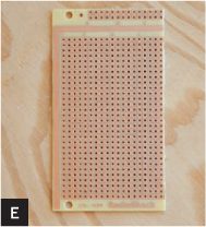
1a. Cut the board to size.
With a black marker, mark the circuit board as shown, and cut it with a saw (Figures D and E).
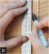
Gregory Hayes (D,E), Damien Scogin (F)
1b. Add the voltage regulator.
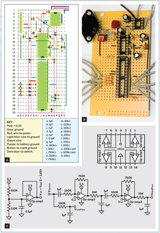
Place the 8-pin DIP socket into the upper right of the circuit board and solder the connections as shown in Figures A, B, and F.

Solder a 1μF capacitor between pin 1 and ground. Solder a wire from pin 8, to be connected later to the loose wire from the switch. Solder 2 wires to the circuit ground, for the crank ground wire and a battery ground wire.
1c. Add the filters.
Solder the 14-pin DIP socket onto the board as shown in Figures A–C and add wires for power: pin 4 goes to 3.3V and pin 11 goes to ground. If you use wire thicker than 22 gauge, you may need a longer jumper on row 10 to go around the socket rather than under it.
Garrick Orchard; Damien Scogin (C)
Build a 1.65V reference voltage using op-amp 1 in the LM324 chip. Solder the two 110kΩ resistors and the 0.1μF capacitor as shown in Figure C. Connect op-amp 1’s output to its own negative terminal.
Now add the smoothing filters and frequency components of the blood pressure sensor. The sensor’s signal follows 2 forks: through a band-pass filter and a separate low-pass filter.
The band-pass filter consists of 2 high and low-pass filters, cascaded together. Make the first high-pass filter by soldering a 1μF capacitor in series with a 160kΩ resistor. Connect the cap to the pressure sensor’s output pin 1, and the resistor to the negative input of op-amp 3. Add gain to the circuit by soldering a 750kΩ feedback resistor between op-amp 3’s output and its negative terminal.
Follow this with a low-pass filter: solder a 16kΩ resistor from the output of op-amp 3 to an open hole on the project board, and solder a 1μF capacitor from this hole to ground.
Feed the output of the low-pass filter into a second high-pass filter made by placing a 1μF capacitor in series with a 160kΩ resistor.
Take the output of the second high-pass filter and feed it into the negative terminal of op-amp 2. Add gain to the circuit by soldering a 750kΩ resistor between op-amp 2’s output and its negative terminal.
Take the output of the gain stage and wire it to the input of a second low-pass filter: solder a 16kΩ resistor from the output of op-amp 2 to an open terminal hole, then solder a 1μF capacitor from this hole to ground. Connect this filter’s output (VBandPass) to the microcontroller’s pin 2 (analog input 0).
Now wire the separate low-pass filter: a 160kΩ resistor from pressure sensor output pin 1 to an open hole, and a 1μF capacitor from this hole to ground. Connect this filter’s output (VLowPass) to microcontroller pin 3 (analog input 1).
1d. Add the pressure sensor.
Solder the pressure sensor in the top left of the board and connect it as shown in Figures A, B, and G.
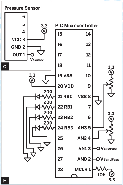
Damien Scogin (G and H)
1e. Connect the microcontroller socket.
Solder the empty 28-pin DIP socket onto the project board as shown in Figures A and B, so its pin 1 is at the bottom. Wire the connections, following Figures A, B, and H, but don’t plug in the microcontroller chip until you’re done soldering.
Wire the power terminals: pins 8 and 19 go to ground, pin 20 goes to +3.3V.
Wire the master clear (pin 1) to +3.3V via a 10kΩ pull-up resistor.
For the LEDs, solder four 200Ω resistors to pins 21–24 of the microcontroller as shown in Figures A, B, and H. Solder leads to the LEDs and back to ground, as shown. The LED order is: power (clear) on pin 21; status (yellow) pin 22; pass (green) pin 23; fail (red) pin 24.
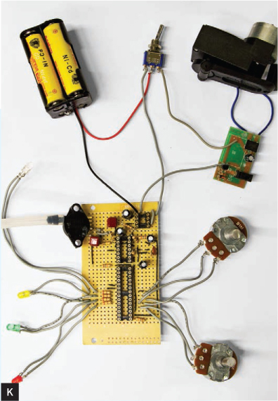
Connect the pots as shown in Figures A, B, H, and K. If the soldering feels cramped, you can use adjacent holes on the power and ground traces.
2. BUILD THE POWER SUPPLY
Now you’re going to mod the flashlight charger to make your hand crank generator.
2a. Salvage the crank and its circuit board.
Flip the flashlight over and remove the 4 screws located in the corners of the outer housing. Remove the outer housing.
Remove the screws holding the hand crank in place, then remove the screws holding the larger circuit board in place (Figure I).
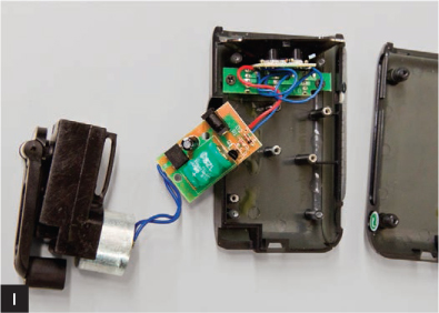
Garrick Orchard
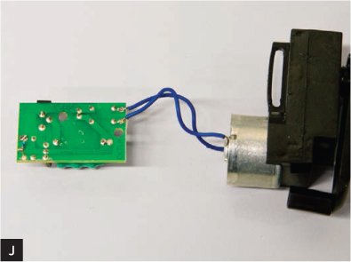
Cut the wires running between the 2 circuit boards. You’ll be left with the crank still connected to the larger board (Figure J).
2b. Unsolder the battery.
Remove it from the board. You’ll replace it later with 3 NiCads for longer life.
2c. Hook up the switch and new batteries.
Solder a wire from the positive terminal of the crank circuit board (marked) to one of the switch’s outer terminals.
Solder the positive wire from the battery holder to the middle terminal of the switch (Figure K). Insert the 3 NiCad batteries into the battery holder (4-battery holder shown here).
2d. Connect it to the project circuit board.
Now connect the 2 loose wires you added in Step 1b: solder the wire from pin 8 on your voltage regulator to the remaining outer terminal of the switch, and solder your crank ground wire to the negative terminal of the crank circuit board (Figure K).
You now have a simple rechargeable power supply. In one switch position, batteries are connected to the crank and can be recharged. In the other position, batteries are connected to your circuit to provide power. This way, the crank is never directly linked to your circuit because that could cause damage.
3. BUILD THE BOX
3a. Drill the lid.
Drill 9 holes total, for the switch and LEDs across the top and the pots across the bottom, following the drilling diagram (Figure L).
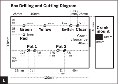
Damien Scogin (L)
3b. Test-fit the components.
Release the lid from the box by removing the 4 corner screws. Check that the potentiometers, LEDs, and power switch fit snugly into the holes (Figure M). If not, enlarge the holes accordingly.
3c. Trim the pot shafts.
Use a clamp and hacksaw to cut the potentiometer shafts to about 12mm (Figure N).

3d. Label the box.
Use a label maker to label the green LED hole “Pass,” red LED hole “Fail,” and the yellow LED hole “Status.” Also label the On and Off positions of the power switch (Figure O).
m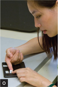
Test-fit the potentiometers, turn them all the way counterclockwise, and put the knobs on, pointing 45° down and to the left. Label the left knob “Diastolic” and the right “Systolic.” To “calibrate” them, label the Diastolic knob’s minimum position (fully counterclockwise) as 60. Turn it all the way clockwise, and mark its maximum as 110 (all units are mmHg). Add intermediate markings, e.g., halfway between 60 and 110 would be 85.
Label the Systolic knob’s minimum (fully counterclockwise) as 100. Turn it all the way clockwise and mark its maximum as 180. Add intermediate markings.
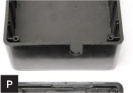
3e. Mount the hand crank.
Saw a rectangular section out of the right side of the box, 10mm wide and 18mm deep, centered 40mm from the right edge (Figure P).
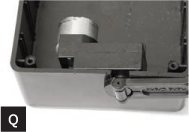
Test-fit the crank. The crank housing should be flush against the inside of the box and also flush with the lid edge (Figure Q).
To make the box lid fit, file down or cut out the lip of the lid where it meets the crank. We filed out a 40mm section of lip starting 25mm from the top side of the box (Figures L and P).
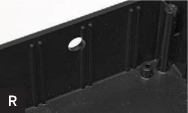
3f. Fit the air hose.
Drill an 8mm hole in the top side of the box, 15mm from the lid edge and 55mm from the left edge (Figures R, T, and U).
Remove the manometer from the tubing that’s attached to the cuff (Figure S). Check that the tubing from the cuff fits through the hole you drilled (Figure T).


4. PUT IT ALL TOGETHER
Place the batteries in the battery holder and put the battery holder in the bottom of the project box. Slide the hand crank into its hole in the side of the box. Insert the LEDs, potentiometers, and switch into the lid. Attach the loose end of the tubing to the pressure sensor. Place the lid on the box and reattach it with the original screws (Figure U).

Finally, turn the potentiometer shafts counterclockwise as far as they’ll go, then reattach the knobs so the markers are pointing 45° down to the left, indicating the minimums you labeled. You’re done!
USE IT
To test your blood pressure with the SEA-BPM:
1. Turn the potentiometers to select the desired systolic and diastolic pressure limits.
2. Switch the device on. The power LED should blink intermittently. If it doesn’t, try charging the batteries by turning the switch to the Off position and winding the hand crank for 30 seconds before turning it on again.
3. Attach the cuff around the arm just above the elbow.
4. Inflate the cuff using the hand pump. Make sure the valve next to the pump is closed. Stop pumping when the yellow Status LED lights up.
5. Gently open the valve a little, allowing air to slowly escape. It should take about 15 seconds for the cuff to fully deflate.
6. Watch the Pass/Fail LEDs to see which one lights up. Green indicates that blood pressure is within the chosen limits. Red indicates that blood pressure is above the chosen limits.
If both light up, it means there was an error during the measurement, likely due to the cuff deflating too quickly or slowly. Try again. ![]()
TOO MUCH PRESSURE
Blood pressure, one of your vital signs, is the pressure exerted by circulating blood on the walls of your blood vessels as your heart pumps. During each heartbeat, it varies between the minimum (diastolic) and maximum (systolic) pressure. In the U.S. classification, you’d ideally have systolic pressure at 90–119 and diastolic at 60–79 millimeters of mercury (mmHg). If either of them is raised, you have high blood pressure, aka hypertension.
Blood pressure rises with age. It’s also affected by exercise, stress, diet, and sleep. If it stays high over time, it can damage the body in many ways, including heart failure and stroke. Hypertension disorder occurs in 5%–14% of all pregnancies and is the leading source of maternal mortality.
 WARNING: This is an experimental prototype. Do not rely on the measurements taken with this instrument. Get your blood pressure checked by a physician.
![]() Download project code: makeprojects.com/v/29
Download project code: makeprojects.com/v/29
Alex Russell, Garrick Orchard, and Carol Reiley are doctoral researchers at Johns Hopkins University.