
TACIT: A HAPTIC WRIST
RANGEFINDER
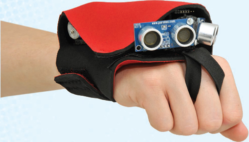
This ultrasonic “bat glove” lets you feel things at a distance.
Gregory Hayes
Tacit is a wearable system that translates the distance to anything you aim your hand toward into pressure on your wrist. The closer the object, the greater the pressure. Sweep your hand around, and the device conveys to you a tactile image of your surroundings. I designed Tacit to help vision-impaired people navigate their environments, but it’s also a fun and effective sensory enhancement for fully sighted people — especially in the dark.
Steve Hoefer (grathio.com) is a technological problem solver in San Francisco. He spends much of his time trying to help technology and people understand each other better.
MY FIRST VERSION OF TACIT WAS A headband with vibration motors that ran faster when objects came closer. But this design had a distracting “mad science” look, and most obstacles, like furniture, are below head level. I also found that motors vibrating against your skull will quickly drive you insane.
I realized that it was my own sighted prejudice to want to attach vision-simulating sensors to the head. The hand is more directable and useful, and putting a device on the back of the wrist leaves the fingers free.
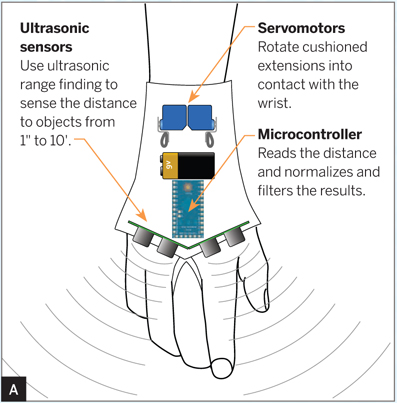
For rangefinders, I used two $30 ultrasonic sensors that detect objects up to 10’ away, angled apart to take in a broader swath. I looked at smaller infrared sensors, but they were confused by sunlight, remote controls, security cameras, and absorbent surfaces. Laser rangers would be the most accurate, but they’re far more expensive.
The rangefinders input to an Arduino Pro Mini, which controls 2 small servomotors to rotate flexible rubber extensions into the back of the user’s hand (Figure A). The servos have a split-second response time, which gives the Tacit an intuitive feel. Everyone who has worn the device figures it out immediately.
Steve Hoefer
1. ASSEMBLE THE ELECTRONICS
To carry all the wiring, I made a shield for the Pro Mini using perf board and headers. Start by soldering 12×1 male pin header rows along the sides of the Mini. Cut a piece of board to 9×12 holes and solder two 12×1 female headers so that it will plug on top of the Pro Mini with 2 extra rows along one side for the power switch.
MATERIALS
Ultrasonic distance sensors, Parallax Ping (2) Maker Shed #MKPX5, makershed.com
Microcontroller, Arduino Pro Mini 5V/16MHz Any 5V Arduino or compatible will work, such as Arduino Nano (Maker Shed #MKGR1) or Ardweeny (Maker Shed #MKSB012) — but not the 3V Arduinos.
Servomotors, hobby, 9 gram (2) such as Turnigy #TG9 or Hextronix #HXT900
Perf board, sized or cut to 9×12 holes
Pin header rows, breakaway: straight female (1×24), straight male (1×24), right-angle male (1×12)
Wire, 20–22 gauge, insulated, stranded, various colors
Battery, 9V
Snap connector for 9V battery
Switch, SPDT slide
Machine screws, 2.5mm×8mm (or 4-40×⅜"), with nuts and washers (6)
ShapeLock, about 35 grams or other low-melting-point polycaprolactone plastic for modeling
PET plastic sheet, ![]() " thick, 3"×3" or larger or other hard flat plastic you can heat and bend. I used PETG from mcmaster.com, part #85815K11.
" thick, 3"×3" or larger or other hard flat plastic you can heat and bend. I used PETG from mcmaster.com, part #85815K11.
Rubber or vinyl strip, 6"×1" I used a squeegee blade.
Neoprene, 3mm thick, 12"×12" or 2mm thick, which is cooler to wear
Hook and loop tape, non-adhesive, 12" aka velcro
Bias tape, 4" from a fabric store
Zip ties, small
Epoxy
TOOLS
Soldering iron and solder
Container, small, filled with hot water
Scissors
Drill and drill bit: 2.5mm
Sewing machine, relatively heavy-duty or thick needle, strong thread, and patience
Converter cable, FTDI 3V3, USB to TTL or a USB cable with an Adafruit FTDI Friend, Maker Shed #MKAD22
Computer with USB port and internet connection
Software: Tacit project code available on Github, gist.github.com/1175994
Template for cutting neoprene download at makeprojects.com/v/29
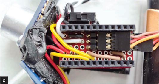
Solder a 6×1 right-angle header to the top of the Pro Mini, for programming, and two 3×1 right-angle headers to the shield for plugging in the 2 servo cables.
Follow the diagram and schematic (Figures B and C) to wire up the shield. Connect the 9V battery (+) to RAW power on the Arduino and the middle (+) servo header pins. Connect battery (–) to Arduino GND through the switch, and directly to sensor and servo grounds. Connect Arduino VCC to sensor power. Finally, connect Arduino digital I/O pins D7 and D8 to the sensor signal (SIG) contacts, and pins D2 and D3 to the servo signal pins.


Damien Scogin (C)
2. MOUNT THE SENSORS AND EFFECTORS
Melt the ShapeLock in hot water and mold it into a bracket that joins the 2 sensors onto the top end of the shield and angles them apart at about 120° (Figure D). Make sure not to block the programming header. For extra hold, run small screws through the sensor board mounting holes and into the ShapeLock while it’s still soft.
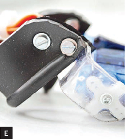
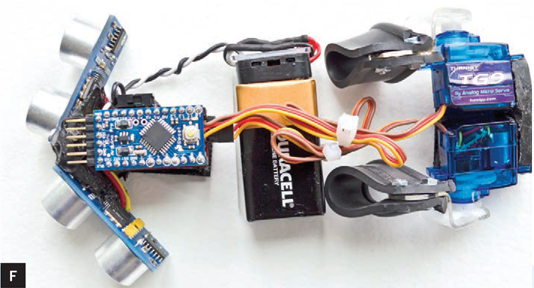
Join the servomotors back-to-back with more ShapeLock. Cut 2 tabs out of the PET plastic, about ⅜"×1¼" each. Heat them crossways over the soldering iron without touching it, and bend each into a symmetrical right-angle S-bracket. Drill and mount each bracket to a loop of cut rubber and epoxy the other end to a servo horn (Figure E). Lay out the 2 assemblies with the battery in between (Figure F). The mechanism is done.
3. PROGRAM THE ARDUINO
Download and install the Arduino IDE from arduino.cc. Download the Tacit project code from gist.github.com/1175994.
Open the project code in the Arduino IDE. In the Tools → Board menu, choose your model of Arduino, and under Tools → Serial Port select the COM port, the highest number if you see more than one.
Plug the USB-TTL cable (or USB cable and FTDI Friend) between your computer and the Pro Mini. Click Verify and Upload to compile the code and burn it to the controller chip.
4. MAKE THE GAUNTLET
Download the template for the gauntlet at makeprojects.com/v/29 and use scissors to cut the shape out of neoprene.
Cut and sew velcro strips onto the neoprene where indicated, and sew on a loop of bias tape to fit the middle finger in front of where the Arduino sits.
Use super glue to attach the corresponding velcro pieces to the electronics and the plastic brackets. The velcro lets you remove the electronics and launder the neoprene. Stuff that’s near the hand can get dirty surprisingly fast.
Electronics sewn into wearable material will inevitably flex, but solder joints can’t take much bending before they break. So wherever possible, you should loop the wire through holes and use zip ties to give each connection plenty of play. I learned this lesson the hard way when I made my Rock Paper Scissors Playing Glove (that’s another story, at makezine.com/go/rpsglove).
IMPROVEMENTS
Now I’m working on Tacit 2.0, refining the software, shrinking the hardware, and using a rechargeable battery with some kind of blind-friendly charging method, either wireless or a magnetically-aligning power plug. ![]()
![]() Download the Tacit project code at gist.github.com/1175994 and the neoprene cutting template at makeprojects.com/v/29.
Download the Tacit project code at gist.github.com/1175994 and the neoprene cutting template at makeprojects.com/v/29.
Many thanks to the designers at Device Design Day, who gave me tons of positive feedback on earlier versions of Tacit.
The circuit and software are released under a Creative Commons BY-NC-SA license.
![]() TIP: Neoprene is a challenge to sew. It drops stitches like crazy on a sewing machine, so you should use the biggest needle you can, with thick thread, and cover the neoprene wherever you sew with a piece of thin scrap cloth. (Thanks to Bethany Shorb of Cyberoptix Tie Lab for the tip!)
TIP: Neoprene is a challenge to sew. It drops stitches like crazy on a sewing machine, so you should use the biggest needle you can, with thick thread, and cover the neoprene wherever you sew with a piece of thin scrap cloth. (Thanks to Bethany Shorb of Cyberoptix Tie Lab for the tip!)