

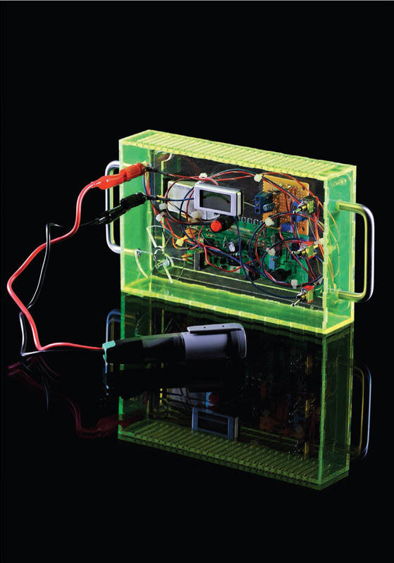
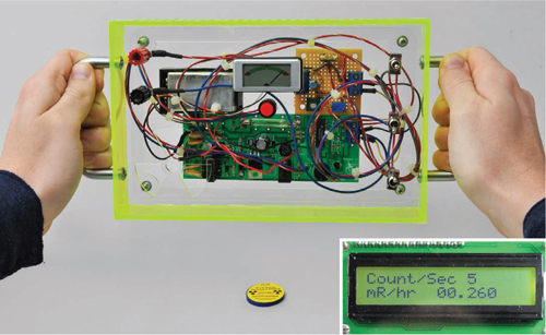
GEIGER COUNTER
This radiation detector clicks, flashes, logs radioactivity levels, and shares its data with the world.
I’ve been designing, making, and selling Geiger counters for 15 years through my company, Images Scientific Instruments. They’re fundamentally simple devices; you just need voltage high enough to run the Geiger-Müller (GM) tube. Anyone can design a counter that will work somewhat, but it’s hard to make one that’s reliable and long-lasting, because the electronics are so touchy.
Last year I was redesigning my basic Geiger counter circuit when the earthquake, tsunami, and nuclear crisis hit Japan. We sold out immediately, and I was so swamped with orders that I had to put my improved design on hold. But I finally finished, and here it is.
You can easily configure this counter to use a variety of GM tubes. Not only will it output a click and an LED flash with each radioactive particle detected, you can also connect it to analog or digital radiation-level meters, a PC for plotting data, a portable SD-card data logger for placing somewhere without a computer, and a true random number generator. It’s also compatible with the Radiation Network (radiationnetwork.com), so you can share your readings with others worldwide.
John Iovine is a science and electronics tinkerer and author who owns and operates Images SI Inc., a small science company. He resides in Staten Island, N.Y., with his wife and two children, their dog, Chansey, and their cat, Squeaks.
SET UP: p.103 |
MAKE IT: p.104 |
USE IT: p.110 |
Gregory Hayes
LOOKING FOR THE TRAIL
Radiation is emitted by the decay of unstable atoms. Geiger-Müller (GM) tubes detect 3 forms of this energy:
α ALPHA RADIATION Free-traveling helium nuclei, can penetrate a few sheets of paper.
β BETA RADIATION Free-traveling electrons or positrons, can penetrate 3mm of aluminum.
γ GAMMA RADIATION High-energy photons, can penetrate several centimeters of lead.
Rob Nance
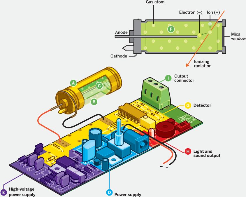
![]() The wall of the GM tube is a cylinder of thin metal or conductor-coated glass. With metal cylinders, one end is mica, which (unlike metal) lets some alpha radiation through.
The wall of the GM tube is a cylinder of thin metal or conductor-coated glass. With metal cylinders, one end is mica, which (unlike metal) lets some alpha radiation through.
![]() The tube is sealed and filled with halogen and noble gases.
The tube is sealed and filled with halogen and noble gases.
![]() An electrode runs through the middle of the tube.
An electrode runs through the middle of the tube.
![]() The power supply takes power from a 9V battery or 12V DC power plug.
The power supply takes power from a 9V battery or 12V DC power plug.
![]() A high-voltage power supply subcircuit uses transistorized feedback with a step-up transformer to create a “ringing choke converter” that converts a 6V, 14.1kHz oscillation induced in the primary coil of the transformer into 325V across the secondary winding. A voltage multiplier boosts this voltage in steps up to about 600V DC. Three Zener diodes let you configure the output voltage to between 300V and 600V DC, to match the GM tube used.
A high-voltage power supply subcircuit uses transistorized feedback with a step-up transformer to create a “ringing choke converter” that converts a 6V, 14.1kHz oscillation induced in the primary coil of the transformer into 325V across the secondary winding. A voltage multiplier boosts this voltage in steps up to about 600V DC. Three Zener diodes let you configure the output voltage to between 300V and 600V DC, to match the GM tube used.
![]() The high voltage is applied across the tube’s wall and electrode, turning them into a cathode and anode, respectively. In the tube’s normal resting state, the resistance between its anode and cathode is very high.
The high voltage is applied across the tube’s wall and electrode, turning them into a cathode and anode, respectively. In the tube’s normal resting state, the resistance between its anode and cathode is very high.
When a radioactive particle passes through the tube, it ionizes gas molecules in its path, which momentarily creates a conductive trail through the gas (like a vapor trail in a cloud chamber). This lowers the tube’s resistance, in a momentary pulse.
![]() In the detector subcircuit, the tube’s cathode directs the momentary pulse to the input of a comparator, alongside a reference voltage tunable by a potentiometer. The comparator cleans up each pulse by outputting a digital 1 while the tube output exceeds the reference voltage and a 0 when it’s lower. This first comparator downstreams its output in parallel to the 3 other comparators on the same quad chip, which simply act as buffers.
In the detector subcircuit, the tube’s cathode directs the momentary pulse to the input of a comparator, alongside a reference voltage tunable by a potentiometer. The comparator cleans up each pulse by outputting a digital 1 while the tube output exceeds the reference voltage and a 0 when it’s lower. This first comparator downstreams its output in parallel to the 3 other comparators on the same quad chip, which simply act as buffers.
![]() One downstream comparator feeds to the base of a transistor, which powers the light and sound output — an LED flash and speaker click — when each particle is detected.
One downstream comparator feeds to the base of a transistor, which powers the light and sound output — an LED flash and speaker click — when each particle is detected.
![]() The other 2 downstream comparators connect to an output connector for output to other devices.
The other 2 downstream comparators connect to an output connector for output to other devices.
After each detection, the high-voltage subcircuit takes some time to recharge the tube. During this “dead time” (which varies with different tubes; 90μs for an LND712), the instrument cannot make detections.
SET UP.
MATERIALS
Get the Maker Shed kit (MKIS1) for a GMT-01 tube, PCB, and all electronics (except voltmeter, data logger, and batteries) at makershed.com, $170.
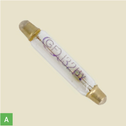
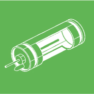
A. Geiger-Müller (GM) tube I recommend GMT-01 ($100), GMT-02 ($75), or GMT-06 ($50) from Images SI (imagesco.com). The GMT-01 is a U.S.-made LND 712 tube that detects all 3 radiation types.
B. Geiger Counter PCB Images SI item #PCB-52. You can also wire this circuit together on a plain breadboard.

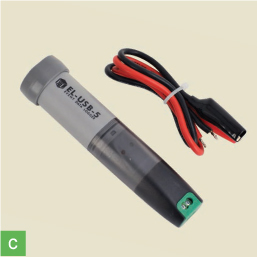
C. Data logger (optional) Lascar Electronics EL-USB-5, item #2127048 from Jameco (jameco.com), $82
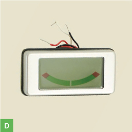
D. Voltmeter (optional, for analog meter), panel-mount display, 1V DC full scale Lascar Electronics EMA-1710, Jameco #2095082, $34
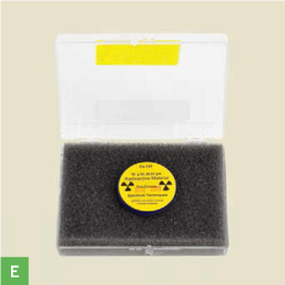
E. Radioactive source (optional) for testing. You can use uranium ore but a more reliable source is cesium-137, which comes in 5μCi (microcurie) and 10μCi plastic sample disks. See makeprojects.com/v/29 for sources.
Gregory Hayes
» Capacitors: 0.01μF, 1kV (4); 0.1μF (1); 10μF, 16V (2); 1,000μF, 16V (1)
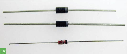
» Diodes: 1N4007 (5); Schottky 1N5817 (1); Zener 100V 1N5271B and 200V 1N5318 (3 total, see Step 1a); Zener 5.1V (1)
» LED
» Power jack, 3.5mm DC, PJ108
» Transistors, NPN: 2N3904 (1), TIP3055 (1)
» Resistors, ¼W: 75Ω (1), 100Ω (1), 10kΩ (5), 100kΩ (1) , 1MΩ (2), 1.8MΩ (1)
» Resistors, ¼W: 470kΩ, 10MΩ or other values dependent on GM tube used; see Step 1c.
» Potentiometer, 1MΩ
» Switches: SPDT toggle (1), SPDT slide (1)
» Transformer, mini step-up Images SI #HVT-03
» Rectifier, 1.5A bridge, W01M, 100V
» Voltage regulator chips: LE33, TO92 package (1); MIC29405, TO220 package (1)
» Comparator chip, quad, LM339, DIP14 package
» Piezo speaker
» Socket, 14-pin DIP
» Terminal block, 3-contact screw or 4-contact
» Wire, insulated, 22 gauge stranded, red and black
» Battery, 9V
» Battery snap for 9V battery
» Fine metal screen (optional) to protect GM tube mica window
For the data logger:
» Battery, 9V
» Computer, Windows-based
» Software for graphing data sets such as Microsoft Excel
For the analog meter, calibration, and enclosure:
» Potentiometers: 47kΩ (1), 100kΩ (1), 500kΩ (1)
» Diode, 1N914
» Capacitor, 1μF
» Resistors: 100Ω (1), 390kΩ (1)
» Switches: SPDT toggles (2), SPST toggles (2)
» Perf board, small I used half of a solderless-breadboard-matching board, RadioShack item #276-170, radioshack.com.
» Ruler
» Small project box, plastic or other non-metal enclosure, Mine measures 5.6"×3.2"×1.5". You can download a template for the laser-cut case on page 101 at makeprojects.com/v/29.
» Machine screws, small, with matching nuts and washers
» High-speed rotary tool e.g., Dremel, for cutting holes in plastic box
For the Digital Meter Adapter:
» Digital Meter Adapter (DMAD), Images SI #DMAD-3, $60 as kit or $90 assembled
TOOLS
» Soldering equipment
» Multimeter
» Radiation Network software and cable (optional) from radiationnetwork.com, $79
MAKE IT.
BUILD YOUR GEIGER COUNTER
Time: A Weekend
Complexity: Moderate
1. ASSEMBLE THE PCB
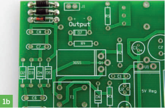
1a. From your GM tube’s specifications, note the voltage required to drive it. This should be an even hundred number between 300 and 600 volts. Match this number by totaling the values of up to three 100V or 200V Zener diodes; for example, use two 200V Zeners and one 100V for a 500V tube.
1b. Solder the Zeners into positions D8–10 on the circuit board, following correct polarity. Fill D8 with a 100V Zener, if used. Nearby jumper J1 bypasses D8, which lets you quickly adjust the tube voltage down 100V.
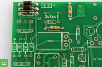
1c. Find the values for anode and cathode resistors R5 and R4 by referring to the specifications for your GM tube.
For the tubes I stock, the recommended anode resistor value ranges between 2.2MΩ and 10MΩ. The LND 712 tube shown in Step 2a needs a 10MΩ anode resistor and a 470KΩ cathode resistor. Solder resistors R5 and R4 where indicated on the PCB.
John Iovine
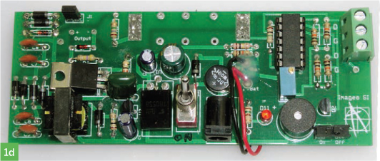
1d. Follow the silk-screened labels on the PCB (or the schematic diagram at makeprojects.com/v/29 if you’re breadboarding) to place and solder all remaining components to the PCB. Be sure to orient all components with the proper polarity.
2. ADD THE GM TUBE
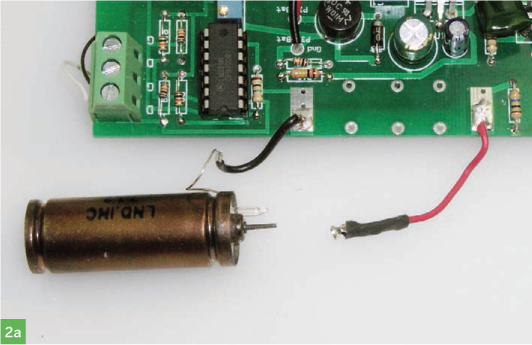
2a. Identify the anode and cathode leads of your GM tube and connect them to the (+) and (–) tube terminals on the board, respectively; the anode (+) terminal is next to R5.
If you’re using the LND 712 tube, you can unplug its center, anode (+) terminal before soldering it to a short wire and soldering the wire to the board.
On glass tubes, the cathode (–) is the end where a short wire extends from the metal cap along the outside of the tube (then penetrates inside).
2b. If your tube has a mica window at the end opposite the terminals, like the LND 712, install a fine mesh screen over it. This will protect the delicate mica while allowing alpha particles to pass.
2c. With a smaller tube, strap it down to the board with a few pieces of scrap wire, then dab on a small amount of glue or epoxy for added support. Take care if using hot glue, because heat can damage the GM tube.
NOTEs: Heat from hot glue or a soldering iron might damage the GM tube.
3. TUNE THE COUNTER
Turn on the Geiger counter and if you have a radiation source, bring it close to the GM tube.
Now simply adjust potentiometer R6 until you hear clicking and see the LED blink. Each click and flash represents the detection of one alpha, beta, or gamma particle passing through the tube (but not all such events are detected; it depends on the tube’s sensitivity).
Without a radiation source, background radiation from natural sources on Earth and cosmic rays will cause the Geiger counter to click. Where I live, background radiation triggers about 16 counts per minute (CPM) with an LND 712 tube.

Gregory Hayes (3)
That’s it — you’ve made a Geiger counter! The terminal block in the corner of the PCB has 2 pairs of output contacts for connecting to other devices: +3V–5V digital pulse signal (labeled “D” on the board) and ground (labeled “G”).
STEPS 4 THROUGH 6 ARE OPTIONAL. They explain how you can connect your Geiger counter’s output to a portable data logger, an analog meter, a digital display with serial output, and the Radiation Network, a public database that pools data from radiation monitoring stations worldwide.
4. CONNECT A DATA LOGGER
4a. Connect a 9V battery to the EL-USB-5 logger and plug the logger into a free USB port on your PC.

4b. Run the installation CD, and select the Set Up and Start option. In the Name/Mode of Operation screen, select Count Events, and on the next screen, set the trigger to “Rising edge” voltage and the LED flash to Off.
4c. For Voltage range, specify 0V–3V. The board outputs 4V–5V, but the data logger loads this output down to about 2.8V.
In the Time Period screen, choose 1 minute. Continue through the rest of the installation wizard, which is all self-explanatory.
NOTES: For logging radiation data from the field with a small, portable setup, I’ve used the ELUSB-5 Data Logger from Lascar Electronics.
You can also use a smart-phone with a data-logging application.
You can specify a different increment than 1 minute, but note that the logger can count up to 32,510 events per period, at a maximum data rate of 100 events per second (with the LED off).
4d. Connect the logger’s 2 alligator clips to the counter’s digital outputs, red to D (digital pulse) and black to G (ground). Cut and strip 2 short wire leads, screw them into the terminal block, and clip to the other ends.
Now the logger is collecting data, and you can bring it wherever you want to take readings.

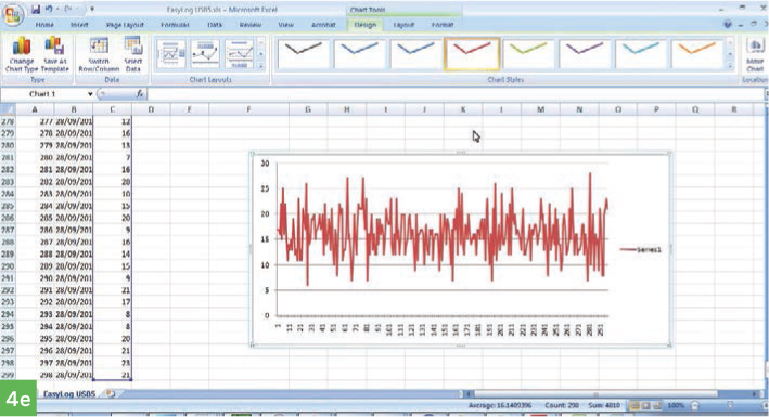
4e. Once your data is recorded, reconnect the logger to the computer via USB and save the data as a text file. You can then open the data file in Microsoft Excel and use the Chart Tools to graph and manipulate it in various ways. The image here shows 298 minutes of background radiation data graphed by CPM, which averaged at around 16.
5. ADD AN ANALOG DISPLAY
Adding an analog meter lets the counter display the current radiation intensity. This circuit is toggle-switchable to display 3 reading ranges, up to 1, 10, or 100 milliroentgens per hour (mR/hr).
5a. On a small circuit board, assemble the circuit as shown here.
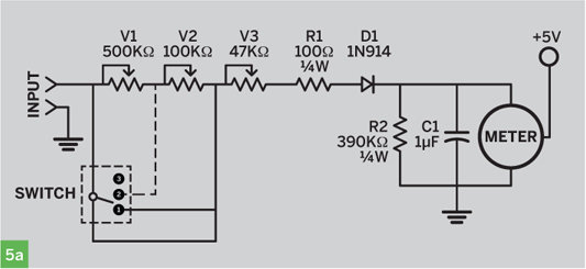
Damien Scogin (5a)
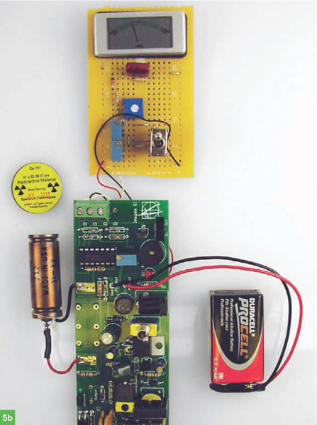
5b. Wire the counter board’s digital output and ground from the terminal block to the meter circuit’s inputs. Also connect the (–) terminal of the meter itself to ground. For the +5V needed to power the analog meter, connect it to any +5V contact on the counter PCB, such as the +5V side of the speaker or of the power jack (you can refer to the schematic or just eyeball the PCB).
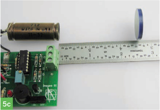
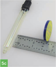
5c. To get a ballpark calibration for the meter (with some GM tubes), we can use a 10μCi cesium-137 sample disk. The chart below shows how far to hold the disk away from the tube to expose it to approximate radiation levels of 1, 10, and 100mR/hr. With the toggle switch in position 1, use a small screwdriver to adjust potentiometer V3 so that the meter reads full scale when the disk is at the distance listed in the table. Flick the switch and move the sample to the second distance for adjusting potentiometer V2 to full scale, then do the same for pot V1.
For tubes like the GMT-01, which detect alpha particles through a mica end window, position the source facing the end. For other tubes, position the source facing the middle of the tube.
Analog Meter Calibration Table |
|||
GM Tube |
GMT-01 (LND 712) |
GMT-02 |
GMT-06 |
1mR/hr (pot V3) |
6" |
6.5" |
0.5" |
10mR/hr (pot V2) |
2.5" |
1.6" |
0.25" |
100mR/hr (pot V1) |
0.5" |
0.25" |
(unknown) |
These values are all approximate, as will be your calibration. Your tube’s response can vary +/– 20% from the tubes I used to write the table here. The strength of your radioactive source and the behavior of your electronic components can also vary, and all these factors affect accuracy.
6. ADD AN ENCLOSURE
6a. Remove the power switch (S1) and the speaker on/off slide switch (S2) from the counter PCB, replace the slide with another toggle, and wire the 2 toggles offboard using 6" lengths of wire.
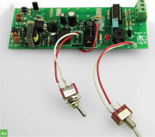
6b. If you added an analog meter, also remove its SPDT toggle switch and connect it offboard with wire leads.
6c. Use a Dremel or other tool to cut holes in the enclosure’s front panel for mounting the toggles and the meter, if used.
If you’re using the GMT-01 or another tube with a window for alpha particles, cut a matching window in the side of the enclosure.
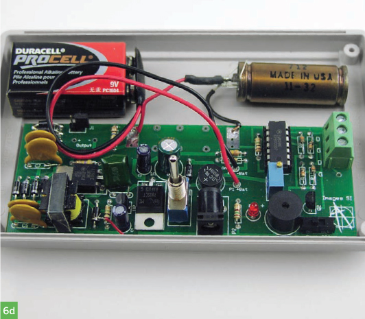
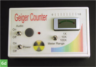
6d. Mount the toggle and meter (if used) to the front panel. Secure the circuitry and tube inside using your preferred method.
For the PCB, you can drill holes in the board and lash it down inside the case using insulated wire anchored around machine screws, washers, and nuts.
For the GM tube, run 4 machine screws longer than the tube’s diameter up through the bottom of the case to surround the tube, secure the screws with washers and nuts, and lash the tube underneath with wire. Align the tube to its window if it has one. Enjoy your new Geiger counter!
NOTES: The plastic will not block much beta or gamma radiation.
Label the panel components and decorate the enclosure as desired.
![]() TEST BUILDERS:
TEST BUILDERS:
Brian Melani and Dan Spangler, MAKE Labs
USE IT.

THE HIDDEN LANDSCAPE OF RADIOACTIVITY
Gregory Hayes; John Iovine (inset)
Test for Radioactive Contamination
If you’re testing for contamination, your GM tube should be sensitive to alpha radiation as well as beta and gamma (like the GMT-01).
Geiger counters can only test for gross levels of contamination that show up clearly above background radiation; they are not the proper instruments for detecting low-level contamination. That said, here is how to test for radioactive levels above background:
1. Establish the background radiation level by measuring CPM for at least 20 minutes, and longer is better. Note the lowest and highest levels and then average them all to establish the baseline minimum, maximum, and average. With my data from Step 4, a 298-minute sample, my average CPM was 16, and min to max was 6 to 28.
2. Position the GM tube very close to the top surface of the material you’re testing, and run the counter, recording the CPM output. The longer the run, the more accurate the results.
3. Compare the radiation output of your sample against your baseline.
Alternative Sound Output
If you want louder clicks from your Geiger counter, you can use the alternative sound output circuit; see the schematic at makeprojects.com/v/29. In this circuit, the pulse signal from the comparator triggers a 555 timer chip, which is set up in monostable mode to stretch out the pulse it receives on its trigger. The output pulse from the timer flashes the LED and outputs an audible click to the speaker via pin 3.
 The Author and Publisher do not make any warranties (express or implied) about the radiation information provided here for your use. All information provided should be considered experimental. Safety and health issues and concerns involving radioactive contamination should be addressed, confirmed, and verified with local and national government organizations or recognized experts in this field.
The alternative circuit’s components (555 chip, caps, resistors) fit on a small breadboard. You can connect it to one of the main board’s digital outputs, or to where the standard light and sound output connects (LM339 pin 14), either replacing the original output or making it switchable.
Digital Meter Adapter
You can do more with your Geiger counter by wiring its digital output to a standard 3.5mm mono earphone jack, connecting ground to the sleeve contact and signal to the tip.
This output jack lets you connect the meter to my company’s Digital Meter Adapter (DMAD) an add-on that shows CPM or counts per second (CPS) along with milliroentgens per hour (mR/hr). Onboard switches also configure the adapter to work as a true random number generator, with multiple ranges. The DMAD (see inset, opposite) has a second 3.5mm plug for output, which lets you connect any of its output functions to a computer via 3.5mm to RS-232 serial cable.
Radiation Network
Want to help keep track of radiation levels nationwide? A 3.5mm output jack, as connected to the Digital Meter Adapter above, will also let your Geiger counter become a monitoring station for the Radiation Network (radiationnetwork.com), home of the National Radiation Map. The network software is sold with an adapter cable ($79 together). ![]()
![]() For schematics and a template for an acrylic enclosure, see makeprojects.com/v/29.
For schematics and a template for an acrylic enclosure, see makeprojects.com/v/29.
More DIY Geiger Counters
By Paul Spinrad
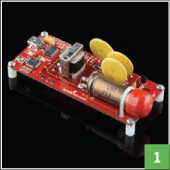
1. USB Geiger Counter
SparkFun Electronics, $150
Has an onboard ATMega328 microcontroller and a U.S.-made LND 712 Geiger tube (Figure 2b, page 105) that detects alpha, beta, and gamma radiation.
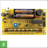
2. MightyOhm Geiger Counter Kit
Maker Shed, $100
makershed.com MKMO1
Solder-it-yourself kit includes ATtiny2313 microcontroller and Russian-made SBM-20 Geiger tube that detects beta and gamma.
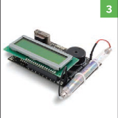
3. Radiation Sensor Board for Arduino, with Geiger Tube
Libelium, €115 ($163)
Currently includes China-made J305β GM tube that detects beta and gamma, but the board works with any tube in the 400V–1,000V range.
Juan Peña (Sparkfun)
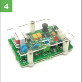
4. Grove Geiger Counter Module
Seeed Studio, $27 without GM tube
Works with Seeed’s $16 China-made J408γ Geiger tube, which only detects gamma radiation, or you can use any other 400V tube.