
PROJECTS RAYGUN VECTOR WEAPON
Raygun Vector Weapon

![]() TIME: 2–4 HOURS
TIME: 2–4 HOURS ![]() COST: $15–$20
COST: $15–$20
Build a mini analog sound-effects circuit.
Gregory Hayes
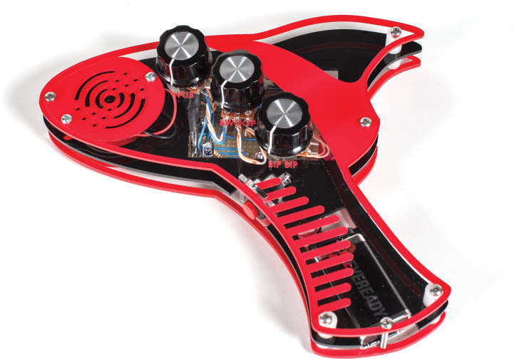
![]() The Vector Weapon is a small, lo-fi, electronic noisemaker circuit that makes raygun-style sounds, from classic pew! pew! noises to evolving death-ray-type tones. It uses common parts and tools, is easy to build, and has plenty of modding potential. It has a built-in amp chip and speaker so there's no need for external amplification. To hear it in action, check out the video at makezine.com/35.
The Vector Weapon is a small, lo-fi, electronic noisemaker circuit that makes raygun-style sounds, from classic pew! pew! noises to evolving death-ray-type tones. It uses common parts and tools, is easy to build, and has plenty of modding potential. It has a built-in amp chip and speaker so there's no need for external amplification. To hear it in action, check out the video at makezine.com/35.
There are 2 options for construction: a basic version that uses PCB-mounted components, and an acrylic-housed raygun version that uses full-size panel-mount potentiometers and switches — and you can also build it from a kit!
How It Works
The Vector Weapon is basically a tiny lo-fi analog synthesizer.
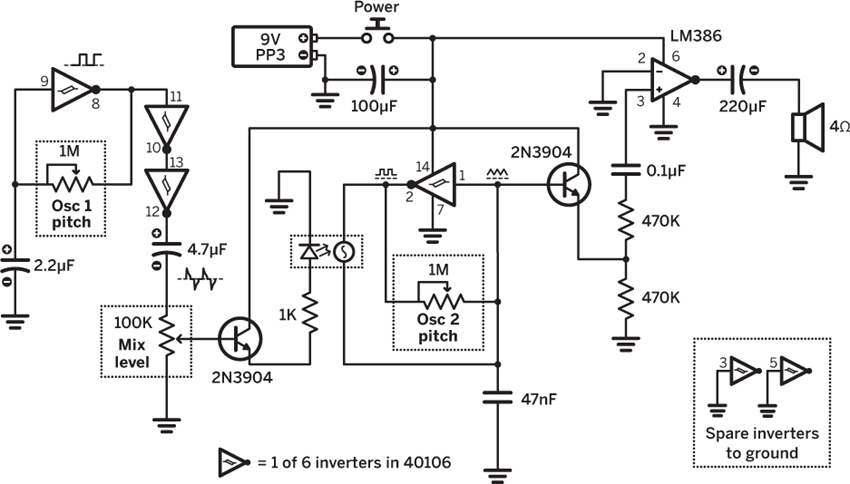
One of the 6 inverters on the 40106 IC, a 1M pot, and a 2.2µf capacitor form a square wave oscillator (Osc 1) that mostly runs slower than the main audio oscillator (Osc 2), and is thus considered a low-frequency oscillator (LFO). This square wave is buffered using 2 more inverters and passed through a capacitor to shape it into a rapidly decaying downward slope. The 100K pot works as a voltage divider that determines how much of this signal is sent to a transistor controlling the LED.

Another 40106 inverter, the light-dependent resistor (LDR), the second 1M pot, and the 47nF capacitor form the main audio oscillator (Osc 2). The LED from Osc 1 is optically coupled to the LDR of Osc 2 so the pitch of Osc 2 rises and falls with the output of Osc 1. The LED also adds a little of its own decay as it won’t go out instantly. The pot connected to Osc 2 sets its lowest frequency, but the LDR is capable of driving it all the way up into the ultrasonic range. The second transistor “listens” to the capacitor charging and discharging and creates a triangle oscillator at the output.
The signal is finally sent through a power amplifier IC (the LM386) to drive an 4Ω speaker.
1. DRILL OUT THE STRIPBOARD
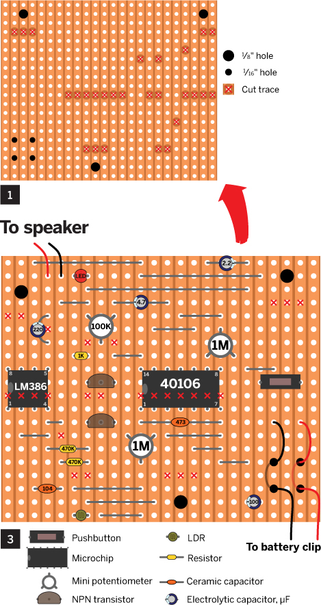
Figure 1 shows the copper side of the stripboard. The large 1/8" holes are for mounting screws, and the smaller 1/16" holes form a strain relief for the battery connector. Use a 1/8" drill bit or knife to cut the copper traces on the stripboard where shown. Clean off the copper side using fine sandpaper, removing any small flakes of copper and preparing the surface for soldering.
2. BUILD THE OPTOCOUPLER
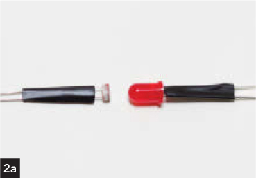
Wrap the legs of the LDR and LED with electrical tape to insulate them, noting the negative leg of the LED, which is usually the shorter of the two (Figure 2a). The LDR is light sensitive, so a few turns of electrical tape are needed to make sure it’s not affected by ambient light. Connect the two as shown in Figures 2b and 2c.


Gunther Kirsch
3. SOLDER THE COMPONENTS
If you’re mounting the circuit in a case, like the acrylic raygun, you’ll need to substitute the trimpots and pushbutton shown in Figure 3 with 4"-long flexible wire jumpers connected to the panel-mount components (Figure 5c, following page). You'll need 6" battery clip leads. Route them through the strain-relief holes before soldering.
Solder in the chip sockets but leave out the chips for now. Be sure the polarized components — the LED, the chips, the electrolytic capacitors, and the transistors — are inserted the right way. The parts are attached to the component side of the board, but Figure 3 also shows the copper-side traces to make it easier to follow the circuit. It's flipped when compared to Figure 1.
NOTE Make sure you ground yourself before inserting the chips, as static electricity may damage them.
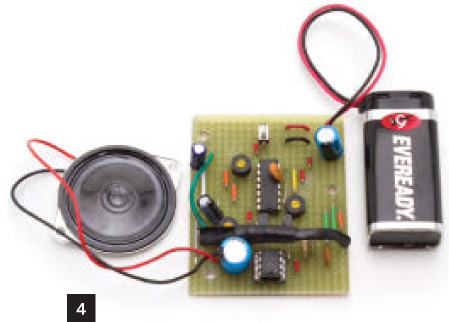
The LDR and LED are shown only where they connect to the board, but they actually pass over the amplifier chip, as shown in Figure 4.
4. TEST YOUR CIRCUIT
When finished, your board should look like Figure 4. Set all the potentiometers to center, attach a battery, and press the button — you should hear something vaguely sci-fi. Adjusting the potentiometers should change the character of the sound dramatically.
If the circuit isn’t acting as expected, check it against the stripboard diagram, make sure your solder joints are clean, check that your battery is good, and try again. Note that it’s possible to turn the potentiometers up far enough that the circuit stops making audible sound; this is not a fault!
5. MOUNT THE BOARD
If you’re making the basic version, use small wood screws to attach the circuit to a piece of wood (Figure 5a). Be careful not to tighten too much as you may crack the stripboard. Use two more screws to attach the speaker, another to attach the battery spring clip, and you should be done.

To make the raygun version, download the housing template from makezine.com/35. Use it to cut the 4 case panels out of acrylic, and to locate pilot drill holes. It may be easier to step-drill the large, ½" hole in the small trigger panel before cutting it to size.
Drill six 1/8" holes in the right and left panels where indicated, for the case assembly screws. The middle panel only needs five 1/8" holes, as the sixth screw will pass through the open battery cutout. Drill 3 more 1/8" holes in the right panel for mounting the board, three 9/32" (7mm) holes in the left panel for the potentiometers, and 2 more 1/8" holes in the left panel for the speaker mounting screws (Figure 5b).

Mount the pushbutton in the trigger panel and solder the leads. Mount the stripboard on the right panel with three ½"-long machine screws and nuts. Align and insert the trigger panel in the right panel slot (Figure 5c).

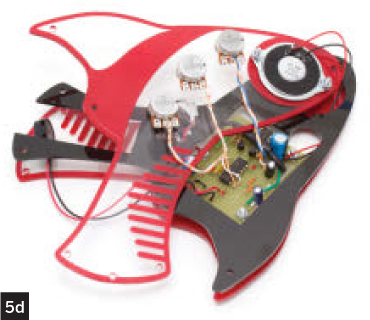
Thread the pot leads through the rectangular opening in the center panel, and the speaker leads through the round opening. Mount the pots in the left panel using their bundled hardware, and the speakers with two ½"-long machine screws and nuts (Figure 5d). Snap in the battery.
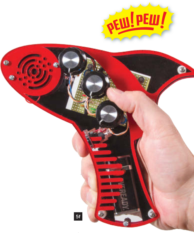
Guide the 1¼" machine screws through the mounting holes, using spacers between middle and side panels. Add nuts and tighten to close up the case (Figure 5e). Attach knobs to the potentiometer shafts and you're ready to conquer the galaxy! ![]()

![]() For diagrams, schematics, photos, and video visit makezine.com/35.
For diagrams, schematics, photos, and video visit makezine.com/35.
Symetricolour designs and builds lo-fi noisemakers, instruments, and kits using electronics and reclaimed materials. To contact Symetricolour, please visit etsy.com/shop/SymetriColour.