
PROJECTS UNIVERSAL TV SLEEP TIMER
TV-Go-Sleep Universal Timer
![]() TIME: A FEW HOURS
TIME: A FEW HOURS ![]() COST: $45–$60
COST: $45–$60
Gregory Hayes
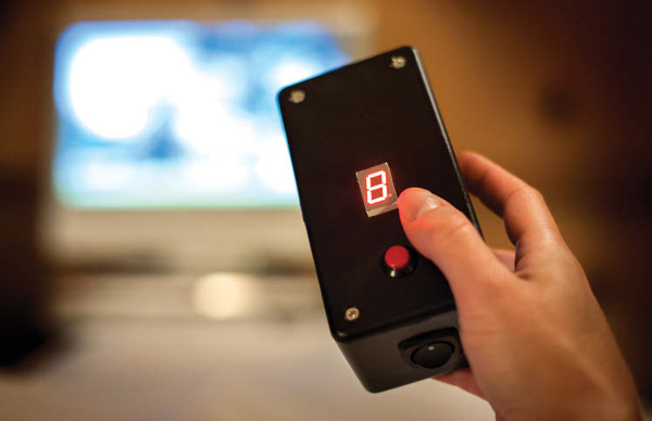
A remote control to turn off any TV after you’ve fallen asleep.
I do a lot of traveling by car, and I usually end up staying in whatever motel is nearest the interstate when I start to feel tired. Often I find that the room has an inexpensive TV that doesn’t have a sleep-timer function. So I created the TV-Go-Sleep, a timer that turns off any TV, after whatever delay time I command. You can build it in an afternoon.
The timer is built around an Arduino microcontroller that’s been loaded with an open source TV-B-Gone library and a few lines of my own code. A simple pushbutton is used to set the delay time, which is shown on a 7-segment display. When the timer expires, the Arduino uses infrared LEDs to transmit all the TV “off” codes it knows, and the TV shuts down.
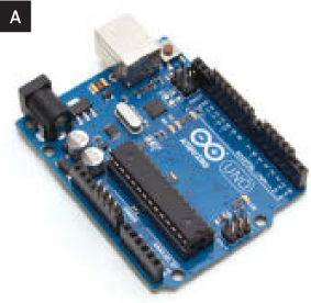
1. Install the header pins.
Break off 3 blocks of male header pins and install them in the female headers on the Arduino: a 7-pin block in pins GND through 8, a 5-pin block in pins 6 through 2, and a 4-pin block in pins 5V, GND, GND, and Vin (Figure A).
2. Mark and cut the circuit board.
Fit the perf board over the header pins, with its bottom (copper side) facing the Arduino. Sometimes an Arduino’s headers aren’t lined up perfectly, so you may have to work the board back and forth to get your pins to fit through the holes.
Mark the board where the pins extend through, then trim the board so it’s a little smaller than the Arduino beneath it. Leave 1–2 extra rows of holes at each end of the board (Figure B).
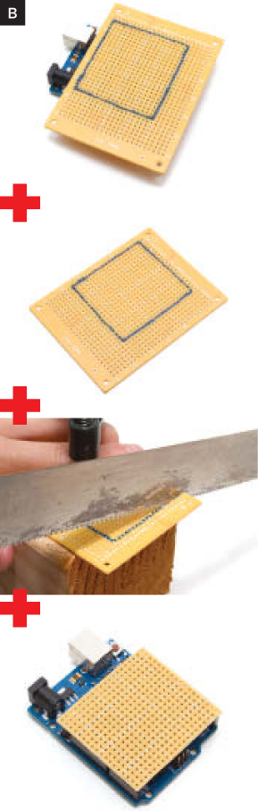
Test fit, then remove the perf board. Remove your header pins from the Arduino.
3. Build the circuit.
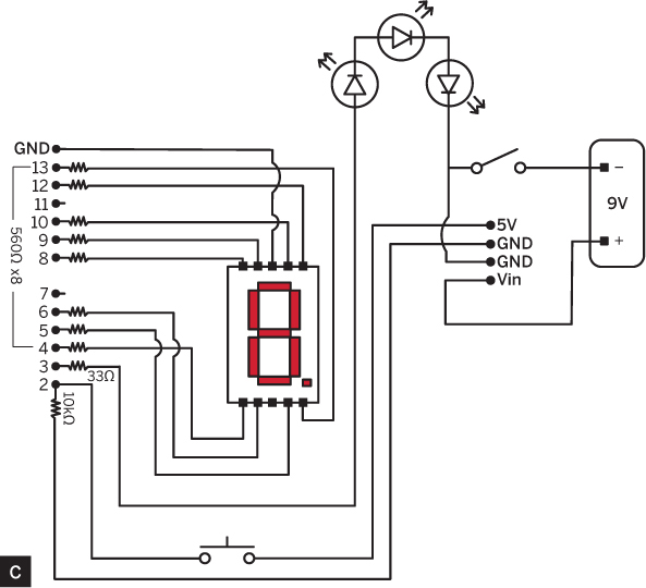
Solder the circuit on the perf board according to the schematic diagram (Figure C, following page).
Gunther Kirsch
Use the 560Ω resistors for the connections to the LED display. The Arduino’s pin 13, used for an all-purpose indicator light, is connected to the decimal point on the display.
CAUTION Don’t try to solder the headers while they’re installed in the Arduino. The heat could damage the microprocessor!
Pin 11 isn’t used because it’s a PWM pin that shares a timer with pin 3. The TV-B-Gone program uses this timer to create the remote control signals on pin 3, but it accesses the clock directly to increase speed. As a result, an LED attached to pin 11 would flicker when the codes are being sent.
The 33Ω resistor controls the current flowing through the 3 infrared LEDs. I chose its value to maximize brightness and service life. A higher resistance will decrease their range; a lower one will shorten their lifespan.
Pin 2 has 2 connections: to ground via the 10kΩ resistor and to the Arduino’s 5-volt reference pin via the pushbutton. When the button is not being pushed, pin 2 is grounded and the input is in the off (or “false”) state. When the button is pushed, the pin is connected to the 5V reference potential, so its state is read as on (or “true”). The 10kΩ resistor limits the current flowing between the 5V and GND pins.
Insert the headers from the bottom of the perf board (the copper side) and solder their connections on the top (the component side), as shown in Figure D. Use a hot iron and melt just enough solder to get a good connection — if you use too much you’ll end up shorting pins together. It may be helpful to insert the header pins in a breadboard and use bits of wire or masking tape to hold the resistor leads in place while soldering.

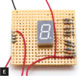
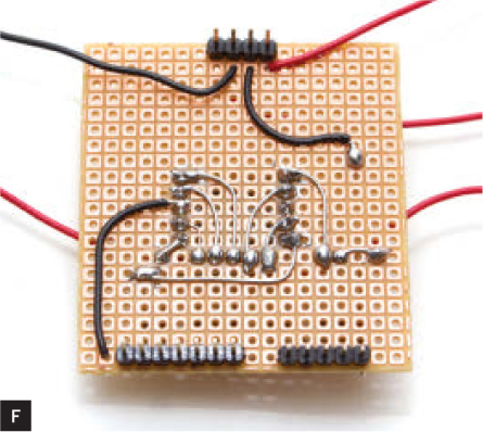
Insert the 7-segment display on the top of the board, midway between the 2 header rows (Figure E). Make its connections on the bottom of the board, so you can solder the leads to each other and to the copper pad where they meet (Figure F).
Cut longer wires for connecting the perf board to the switches and the infrared LEDs.
4. Mount the infrared LEDs.
Drill 3 holes in one end of the enclosure (Figure G) and insert the 3 infrared LEDs so they can be wired in series: anode-to-cathode-to-anode-to-cathode. The anode is the longer lead.

Why 3 LEDs? Their lenses focus the IR light into a fairly narrow beam, so adding more LEDs increases the likelihood that one of the beams will reach the TV’s IR receiver. Don’t make them perfectly parallel; let the lenses point in slightly different directions.
Drip some hot glue on the backs of the LEDs to hold them in place, and then solder them in series.
5. Mount the switches and display.
In the opposite end of the enclosure, make a hole and install your on/off switch (Figure H).

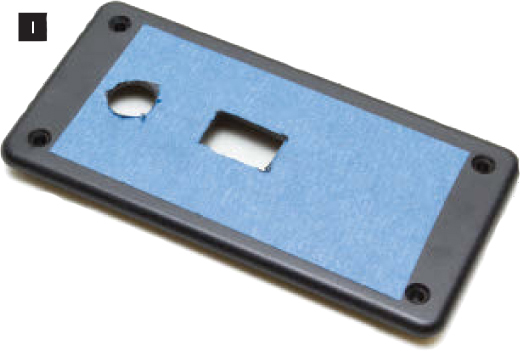
In the enclosure’s lid, make a rectangular hole for the 7-segment display. The Arduino just barely fits within the width of the RadioShack enclosure, so check the alignment carefully before you start cutting. Leave room for a hole for the pushbutton switch, preferably below the display. Go ahead and cut that hole now, too (Figure I).
TIP Masking tape makes it easier to see pencil marks on the lid, and provides a little protection from stray tool marks as well.
Insert the display through the rectangular hole and mount the board under the lid with double-stick tape. Install the pushbutton.
Solder the leads from the perf board to the switches and IR LEDs. Note that the on/off switch interrupts the ground side of the battery. I did it this way to provide an easy grounding point for the infrared LEDs. Hot-glue the battery clip in the bottom of the case (Figure J, following page).

6. Install and program the Arduino.
Install the Arduino on the header pins. Be sure to line it up properly!
Use a USB cable to connect the Arduino to a computer (Figure K). Download the Universal Sleep Timer Arduino code and the TV-B-Gone for Arduino library (main.h and WORLDcodes.cpp) from makezine.com/35. Open the files in the Arduino IDE and upload them to the device.

7. Close it up.
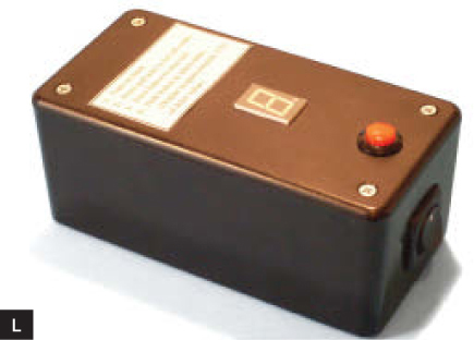
Disconnect the USB cable, install the 9V battery in the enclosure, and screw the lid in place. I used double-sided tape to attach the instructions to the lid of the box (Figure L).
Now Log Some Tube Time
When you turn on the power switch, the decimal point will flash a few times, and then the display will read “9.” This corresponds to a sleep delay of approximately 90 minutes. Each time the button is pushed, the sleep delay is shortened by roughly 10 minutes.
If you press and hold the button, the TV-Go-Sleep goes into test mode, and it will begin sending all of its “off” codes.
Place the device where you plan to leave it for the night, and run the test to verify that the TV turns off. If the TV is still on when the test is finished, try realigning the device or moving it closer to the television set.
If the TV goes off and then comes back on, it must be responding to 2 different codes being transmitted from the timer. If that should happen, run the test again, but be ready to press the button when the TV turns off. This will stop the test at that point. Later, when you’re asleep and the timer runs down, the device will only send codes until it reaches the point where you stopped the test.
If you can’t get the TV to turn off, then its code may not be in the TV-B-Gone library. Check back at righto.com for updated libraries.
Thanks to Donal Morrissey for showing how to put the Arduino into a low-power mode (makezine.com/go/morrissey). And special thanks to Ken Shirriff, who created the Arduino TV-B-Gone code (makezine.com/go/shirriff) that’s the backbone of this project. ![]()
Tom Rodgers is a physics teacher and robotics coach in Virginia Beach, Va. He has tinkered with gadgets and gizmos all his life and has subscribed to MAKE since before the first issue was published.