To make your bot stay in the arena, you must teach it to avoid a black line. Then you can build an arena with big white paper as the floor and black tape as the border.
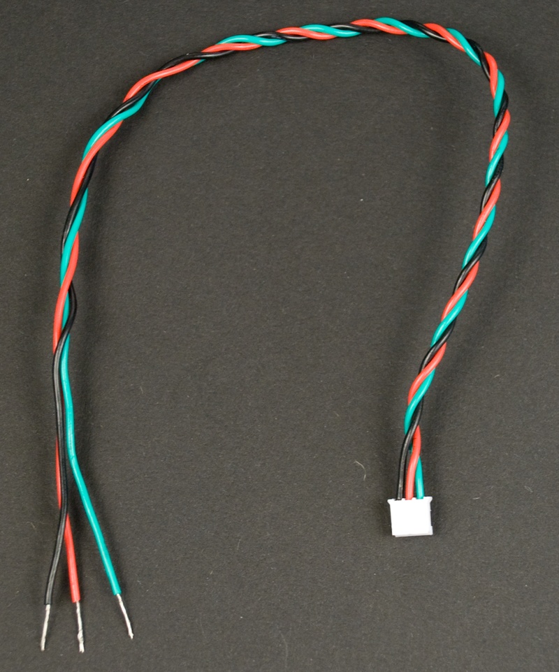
Let’s connect the reflection sensor to Arduino. Prepare the cable by cutting the end that doesn’t fit to the sensor. In our case, the small white connector fit to the sensor and we left it in place. The big black connector didn’t fit anywhere, so we cut it away. Strip the free wires for connecting to Arduino (Figure 2-6).
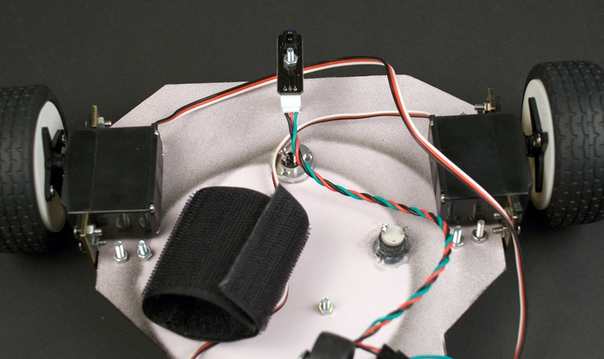
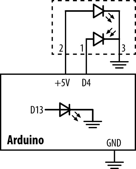
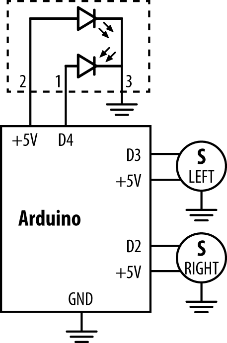
Connect free sensor wires to Arduino as shown in the circuit diagram for helloreflection.pde (Figure 2-7). Connect the red plus wire to +5V, and the black ground wire to GND. Connect the green data wire to D4. (Figure 2-8). Use the ScrewShield to keep the wires in place (Figure 2-9).

For line avoidance, we use a typical reflectivity sensor. We read it with Arduino’s digitalRead() function.
The value tells how much light is reflected back from the surface. It returns HIGH (true, 1) for a white surface. Black doesn’t reflect light back, so the sensor gives a LOW value (false, 0).
// hellorefelection.pde - turn led on if line detected // (c) Kimmo Karvinen & Tero Karvinen http://MindControl.BotBook.com const int tinyLedPin=13; //const int linePin=4; void setup() { pinMode(tinyLedPin, OUTPUT); pinMode(linePin, INPUT); } void loop() { if (LOW == digitalRead(linePin)) { //
digitalWrite(tinyLedPin, HIGH); } else { digitalWrite(tinyLedPin, LOW); } delay(20); //
}
-
We use the tiny surface-mounted LED that’s built into Arduino to show if we’ve detected a line. The reflectivity sensor also has its own LED, so don’t confuse them (Arduino’s built-in LED is connected to pin 13 and is right on the Arduino board itself).
-
LOW from the reflectivity sensor means black.
-
Long running loops should always have some delay. Otherwise the program would take 100% of CPU time on any single core CPU (such as the one on Arduino), no matter how fast it was.
Test your reflectivity sensor by holding it near white and black surfaces.
Lighting an LED is a nice way to test the sensor, but what we really want to do is turn to avoid the border. Something like this:
void loop()
{
        while (lineDetected()) turn();
        forward();
}
You already have all the knowledge to do this (in separate parts) from the previous examples, so let’s combine them. Connect the servos and reflection sensor according to the circuit diagram for avoidline.pde (Figure 2-10).
// avoidline.pde - turn when black line seen
// (c) Tero Karvinen & Kimmo Karvinen http://MindControl.BotBook.com
const int linePin=4;
const int servoLeftPin=3;
const int servoRightPin=2;
void setup()
{
pinMode(linePin, INPUT);
pinMode(servoLeftPin, OUTPUT);
pinMode(servoRightPin, OUTPUT);
}
void loop()
{
while (lineDetected()) turn(); //
forward();
}
bool lineDetected()
{
return ! digitalRead(linePin); //
}
void forward()
{
for (int i = 0; i < 10; i++) {
pulseServo(servoLeftPin, 1500+500);
pulseServo(servoRightPin, 1500-500);
}
}
void turn() //
{
for (int i = 0; i < 30; i++) { //  pulseServo(servoLeftPin, 1500+500);
pulseServo(servoRightPin, 1500+500); //
pulseServo(servoLeftPin, 1500+500);
pulseServo(servoRightPin, 1500+500); //  }
}
void pulseServo(int pin, int microseconds)
{
digitalWrite(pin, HIGH);
delayMicroseconds(microseconds);
digitalWrite(pin, LOW);
delay(5);
}
}
}
void pulseServo(int pin, int microseconds)
{
digitalWrite(pin, HIGH);
delayMicroseconds(microseconds);
digitalWrite(pin, LOW);
delay(5);
}-
Keep turning as long as the sensor sees a black border. When the
while()loop is done, the bot is away from the border. BecauselineDetected()already returns true or false, we don’t have to put in an explicit comparison. Because there is just a single line (turn()) inside the while-loop, we don’t need braces ({}) here.-
When the bot is in the white arena, linePin is HIGH, which Arduino represents internally as the number 1. In a boolean context, 1 is interpreted as true (and 0 is false). And according to boolean algebra, not true is false. Thus,
lineDetected()returns false when the robot is on a white surface.-
The new function
turn()turns right. It’s almost same asforward(), but the count of loop iterations and the direction of right servo have changed.-
Every call to
turn()takes some time by runningpulseServo()in a loop. Otherwise the bot would only turn just enough to go parallel to the black border. Feel free to play with the values to alter the turns to work as you need them to.-
Make the right wheel spin the opposite direction. Just change the plus to minus. We send the same signal, 2000 µs, to both servos, because the right one is mounted backwards on the frame.