Your line-avoiding robot is otherwise great, but it can be a bit of an annoyance to run after it while you’re holding the USB cable. It’s time for your robot to get its very own power source.
We can’t use a regular 9-volt battery for the bot, as it doesn’t have enough juice to power motors, the LED, and the NeuroSky dongle. It’s also much nicer to use a high-capacity rechargeable battery, because it can keep your robot running 10 times longer without the need for a battery change.
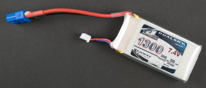
We used DualSky 1300 mAh 30C 2s1p 7.4 V battery (Figure 2-11). What do all these values mean? 1300 mAh (milliamp hours) or 1.3 Ah is the battery capacity. Higher value means longer running time. 30C is the discharge capacity for one hour. In this case 1300 mAh * 30 = 39000 mAh = 39 Ah. 2s1p means that battery has two 3.7 V cells in parallel. So together they give you 7.4 V, the output current. The recommended input voltage for Arduino Uno is 7–12 V.
Warning
Always use strong batteries carefully. Acquire and follow battery-specific instructions. A short circuit can lead to heating, fire, or even explosion.
Batteries often use one set of cables for charging and other for discharge (powering your device). In our battery, the blue connector is for discharge and small white one is for charging (Figure 2-11). Be careful to use the correct one.
Let’s connect the battery and the key switch. The ground wire from the battery connects directly to Arduino, but the positive wire has a power switch in the middle (Figure 2-12). You need to use a connector for the battery, so that you can disconnect it for charging.

The battery cable has a connector on one end and free wires on the other. It connects the battery to the power switch and to Arduino GND. Use a connector suitable for your battery. Our battery came with a male DC3 connector, so we use a DC3 female for the battery cable.
Leave the black free wire 25 cm long. Cut one red free wire to 8 cm and another one to 15 cm. Strip the wires and solder the black wire and shorter red wire to the switch.
Put heat shrink tubing over the soldered joints (Figure 2-13). Leave some tubing for the other end of the red wire, too (Figure 2-14). You can’t add tube after you’ve soldered both ends.
Solder red wires to the power switch and put some heat shrink tubing on them (Figure 2-15). Connect the free red wire to Arduino VIN and the black wire to Arduino GND (Figure 2-16).
Now you have connected the battery and the switch (Figure 2-17).
The power source is often omitted from circuit diagrams. We didn’t use a symbol for USB power earlier, so we won’t be using one for the battery all of the time either.
Well done! You have now built a complete line-avoiding robot. Let it play in the arena for a while and enjoy a cup of coffee (or appropriate celebratory beverage).