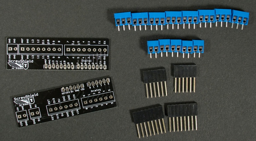
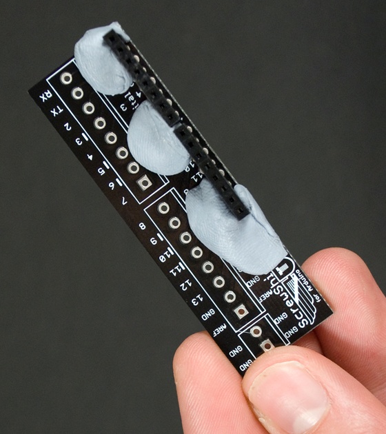
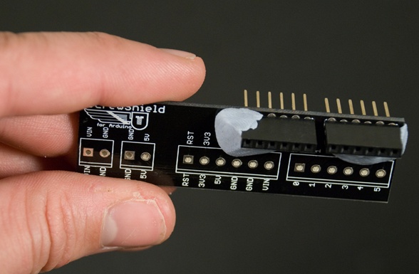
Start by putting two 8-pin headers (see Figure A-1) into the pin holes of the “digital” wing (the one with RX and TX pins). Use some poster putty such as Blu-Tack to hold pins in place (Figure A-2). Otherwise they will easily get misaligned when you are soldering them from the other side.
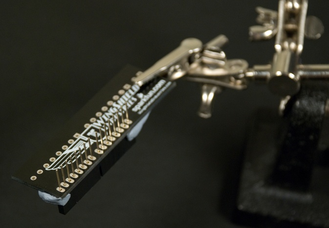
Mount the wing to third-hand tool or similar (Figure A-3). You can’t hold it yourself while you are soldering, as you need one hand for soldering iron and other for the solder. Turn the wing upside down and solder the pins in place.
Now you need to do the same thing to the other wing. Secure the 6-pin headers with poster putty. Turn the wing upside down and solder (Figure A-4).
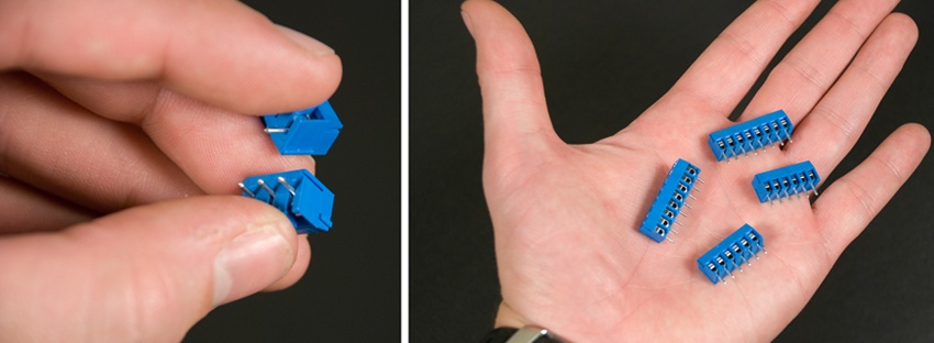
The ScrewShield package includes a variety of terminal blocks. They can be connected by vertically sliding them together. Form two 6-pin blocks and two 8-pin blocks (Figure A-5).
Now use poster putty to put the terminal blocks in place. 6-pins blocks go to the “analog” wing and 8-pins blocks to the “digital” wing (Figure A-6).
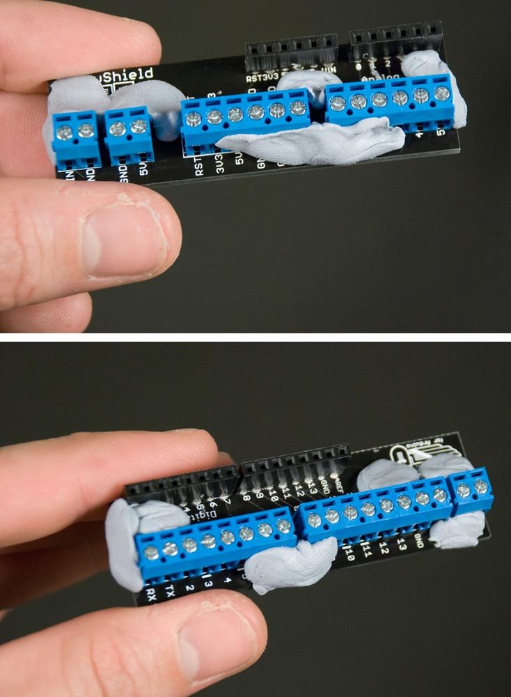
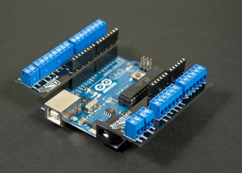
Solder the terminal blocks to wings. Push the wings to Arduino ports, and you are done (Figure A-7).