The previous chapter focused on the repository and the functionality available from PeopleSoft Cloud Manager to simplify and automate the process of downloading and managing application packages. This chapter will focus on how you can design and manage the infrastructure on which those application packages will run. Cloud Manager uses the concept of topology to help define the various components within your PeopleSoft environment.
During the process of creating a new topology, you will determine how many nodes your PeopleSoft environment will run on, what operating system those nodes will run, the computing power of each node including CPU (virtual CPU) and RAM, and what PeopleSoft components are installed on each of the nodes. Your business requirements may dictate that your PeopleSoft environments include a Linux node for mid-tier components, one Windows node for PeopleSoft client tools which are used for development and updating your system, and a separate Linux node for the database. Within the Cloud Manager Topology, you can define and control these deployment features and provision the environment the way you need. Along with creating custom topologies to meet your needs, PeopleSoft Cloud Manager also comes with three topologies predefined for your use: Lift and Shift, PUM Fulltier, and Lift and Shift – DbaaS.
Accessing the Topology Home Page
Topology tile on the Cloud Manager home page

Three delivered PeopleSoft Cloud Manager Topologies
What Is a Topology?
Defines the infrastructure layout of the PeopleSoft environment that will be created in the Oracle Cloud
Allows the administrator to choose what operating system the node will run on
Determines how much virtual CPU and memory are allocated to each node within the topology
Indicates which PeopleSoft components are installed on each node within the topology
Topologies are used within PeopleSoft Cloud Manager to help administrators create environments that meet the needs of the users of that environment. Administrators may create a development topology that is small and consists of only one node, a test topology that can be used when test environments are needed, and a production topology that consists of multiple nodes that are bigger and more powerful than the developer topology allows for. This provides added functionality, consistency, and reusability to PeopleSoft Cloud administrators and makes provisioning environments across the enterprise more straightforward.
Delivered Topologies
PeopleSoft Cloud Manager comes delivered with three unique topologies that can be used in the process of instantiating new PeopleSoft environments in the Oracle Cloud. These three topologies are Lift and Shift, PUM Fulltier, and Lift and Shift – DbaaS. Each of these topologies has a distinct use case and specific purpose. Additionally, these provided topologies can typically be used as a good starting point in creating a new custom topology that better meets the needs of your organization. Let’s explore each of these delivered topologies in more detail.
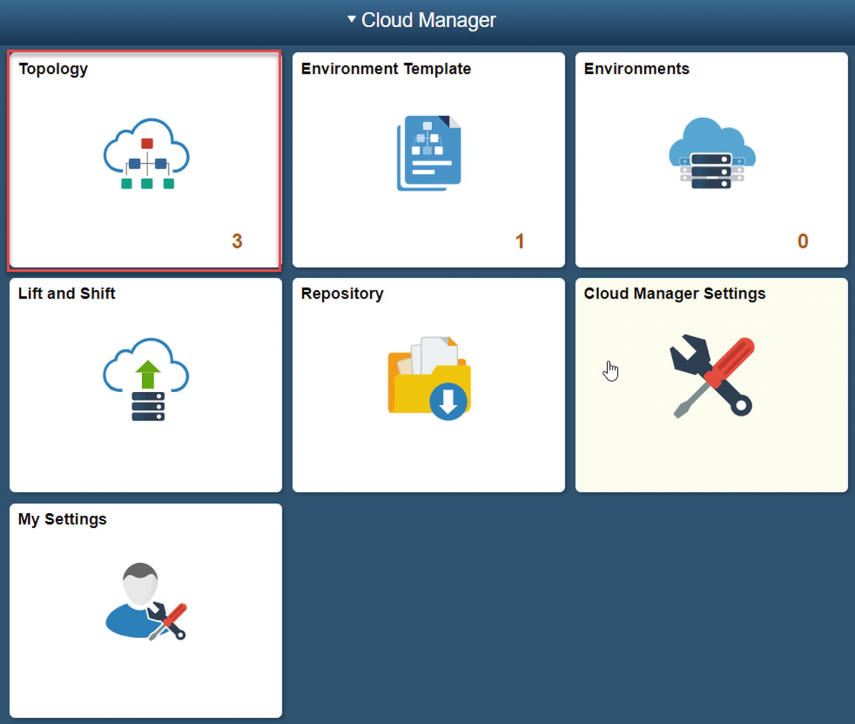
To access the node specific detail within each of the delivered topologies, you can get there by clicking directly on the row containing the name description of the topology you would like to see in more detail. This will bring you to the Topology Definition page. This page provides detail as to how many nodes are defined within topology, the environment type of the node, the size of each node, the operating system of each node, and the disk space of each node.
Lift and Shift
Lift and Shift topology
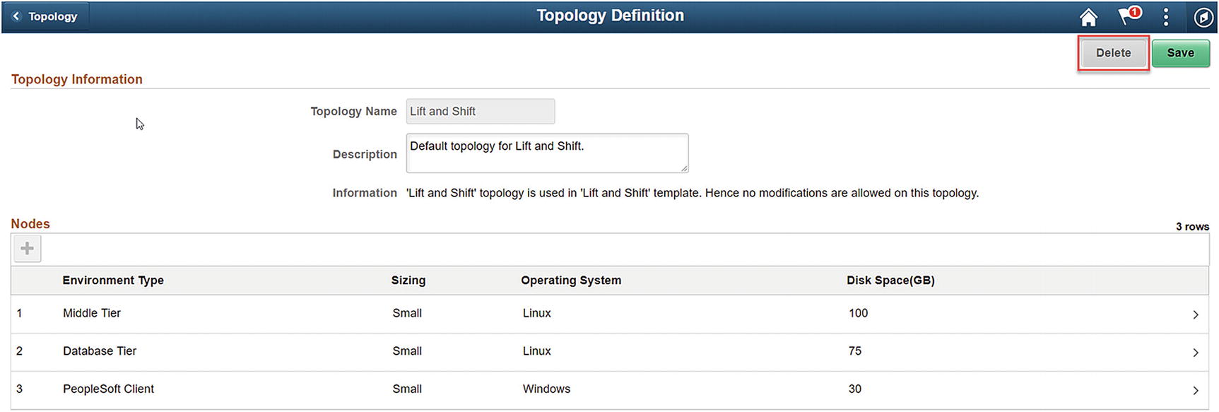
Middle Tier Node
Lift and Shift – Middle Tier
Database Tier Node
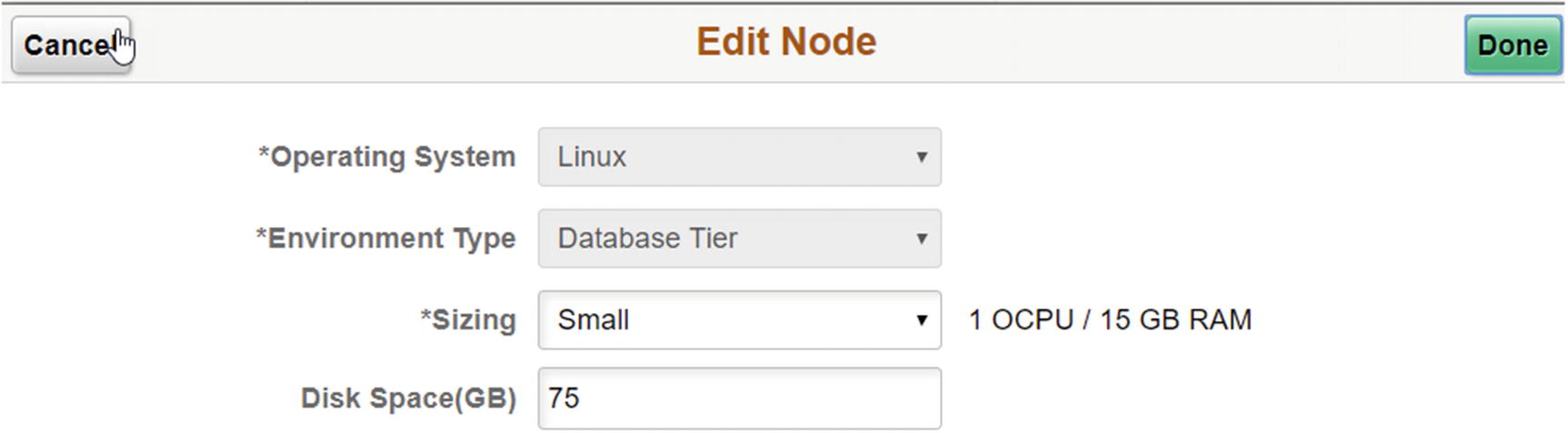
Lift and Shift – Database Tier node
PeopleSoft Client Node
Lift and Shift – PeopleSoft Client node
PUM Full Tier
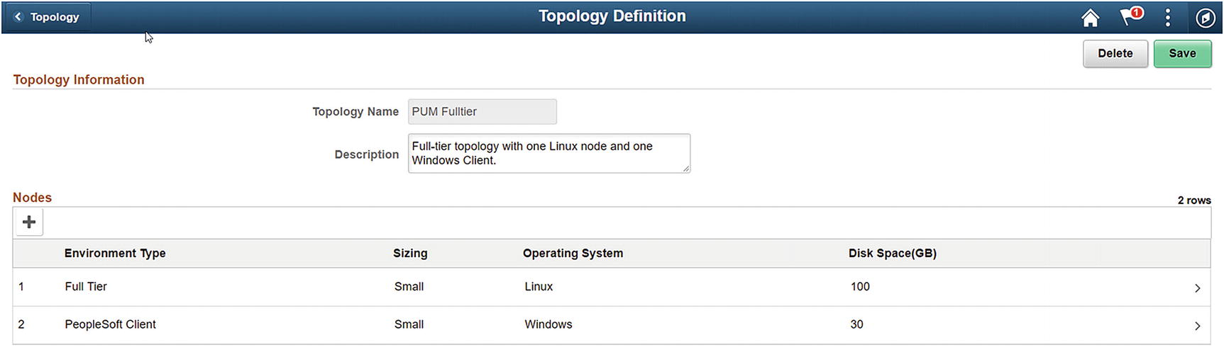
PUM Fulltier
Full Tier

PUM Fulltier – Full Tier
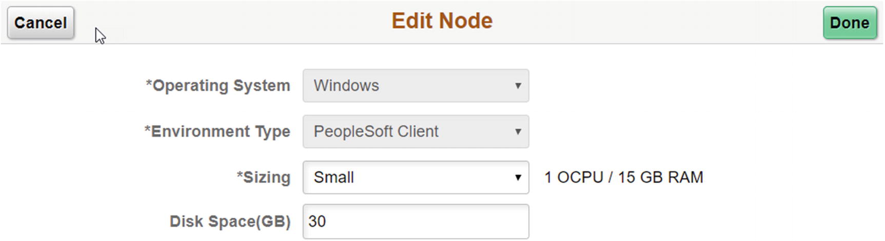
PeopleSoft Client Node
PUM Fulltier – PeopleSoft Client
Lift and Shift – DBaaS
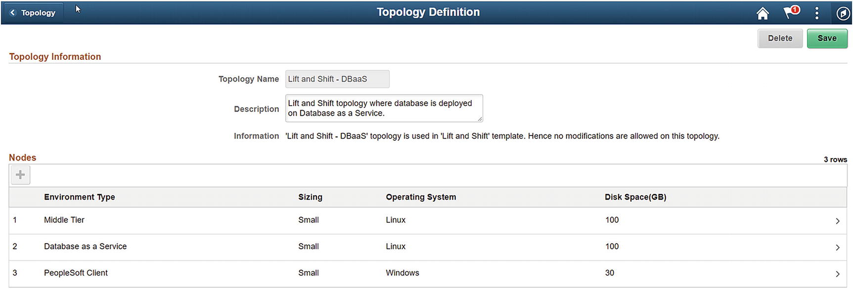
Lift and Shift – DbaaS
Middle Tier
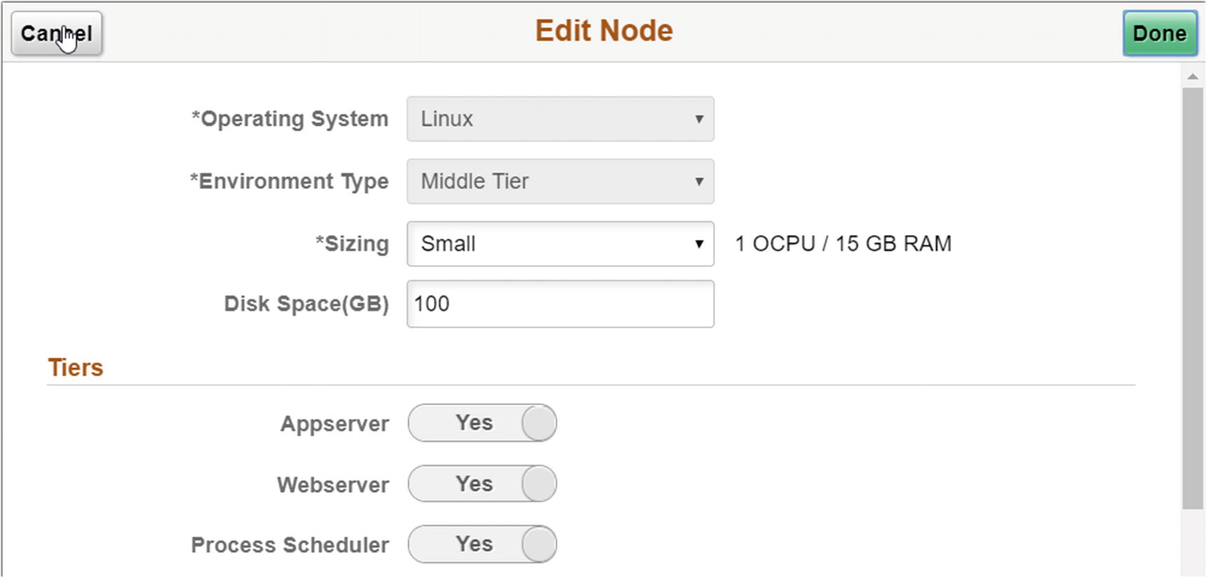
Lift and Shift – DbaaS – Middle Tier
Database as a Service
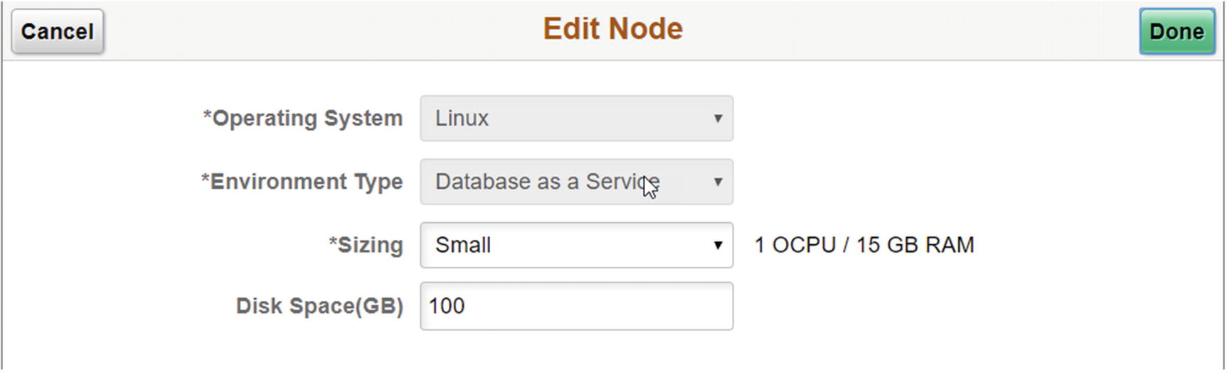
Lift and Shift – DBaaS – Database as a Service
PeopleSoft Client
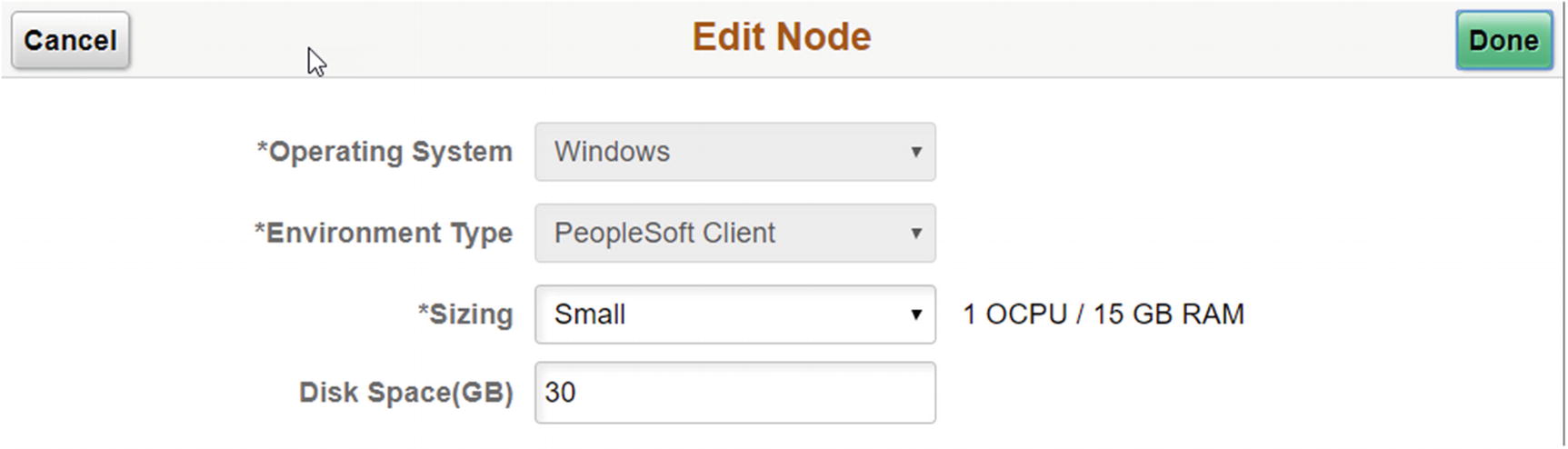
Lift and Shift – DbaaS – PeopleSoft Client
Creating a New Topology
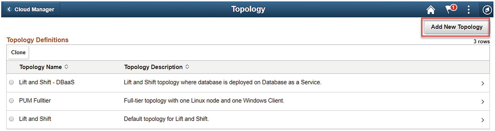
Add New Topology
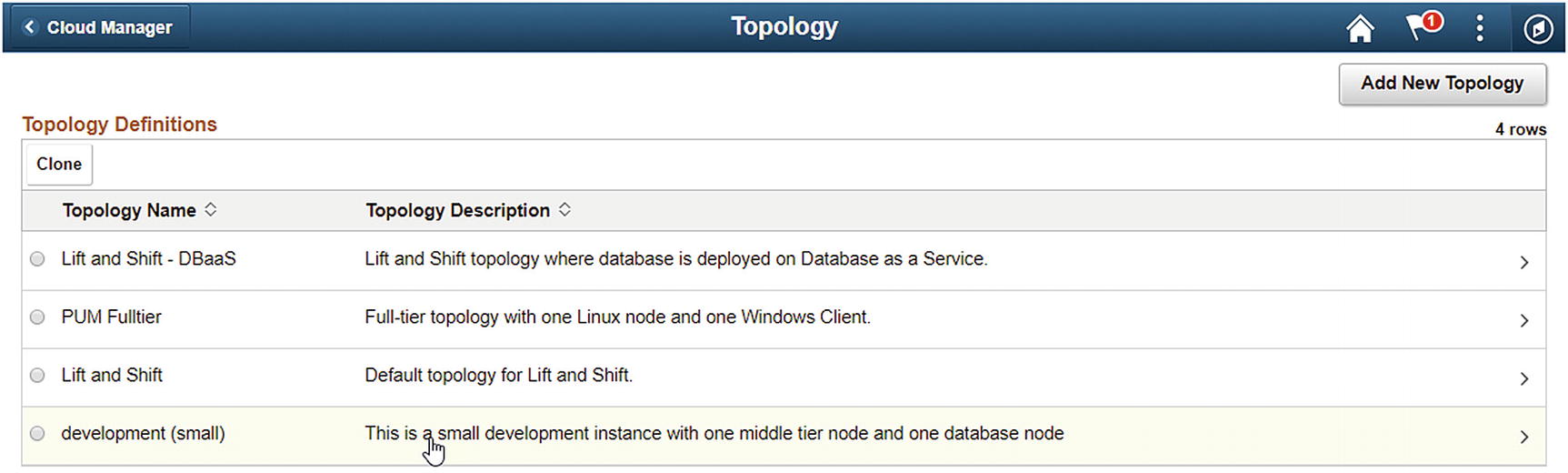
Topology Name : This can be anything you like. It should clearly define what the topology provides in terms of infrastructure to the eventual instance. In our case we are calling this new topology “development (small).”
Description: Again, this can be anything you like; however, the more clearly you define the topology, the less opportunity there will be for accidental misuse. In this example, we are using “This is a small development instance with one middle tier node and one database node” as the description (Figure 6-15).
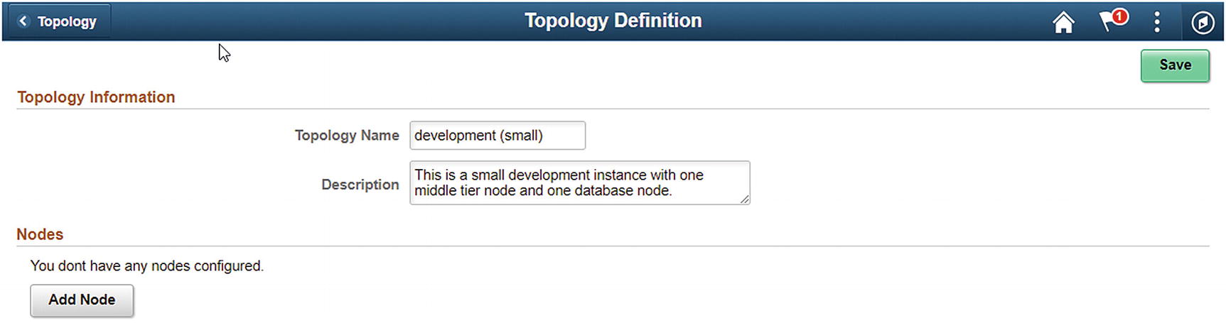
Topology Definition
Now that you have your topology defined, you will next need to the appropriate nodes to your topology.
Adding a Node
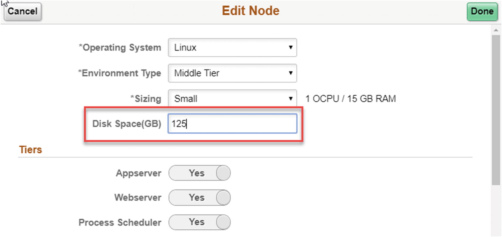
Operating System: This is a drop-down box from which you can select either Linux or Windows. For this example, we are going to select Linux.
Environment Type: Here you need to select what type of node this will be. If your operating system is Linux, you will choose from one of the following choices: Database Tier, Database as a Service, Elastic Search Server, Full Tier, or Middle Tier. If you are creating a Windows node, you can only select PeopleSoft Client. For this example, we will select Middle Tier.
Sizing: Here you can choose from the VM sizes you have defined on the VM Size page in Cloud Manager Settings. PeopleSoft Cloud Manager comes delivered with small, medium, and large sizes defined. For this example, we will choose a small size VM.
Disk Space: You will need to provide how much disk space in gigabytes you want allocated to this node. Here, we will follow the standards set in the delivered topologies and allocate 100 GB.
Tiers: The tiers deployed in this instance are appserver, webserver, and process scheduler. You cannot, at this time, modify this setting.
Features: Is Cobol installed on this node or no? For this example, we will leave this set to No.

Add Node detail

Node successfully added
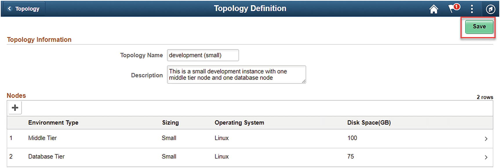
Save the new topology
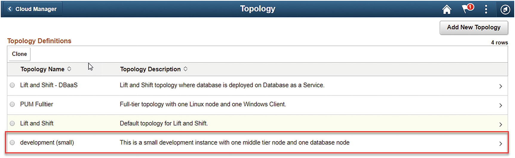
Newly created node, available for use
Topology Rules
For a topology to have all the components necessary to properly set up and configure a PeopleSoft environment, there are rules for the types of nodes that can or must be included within each topology. These rules are important as you start to define your custom topologies for use in your environment.
If you choose to have a node that is defined as full-tier node, PeopleSoft Cloud Manager will not allow you to have another full-tier node, nor can you have a mid-tier, database, or Database as a Service node included in the topology. You are free to add either a Window Client node or an Elasticsearch Server node if you like.
If you choose to have a node defined as a mid-tier node, given that the mid-tier node splits up some components found in the full-tier node, PeopleSoft Cloud Manager will not allow you to have a full-tier node. Additionally, in order to have a complete topology, you must include either a database or Database as a Service node in the topology. Here too, you can add a Windows Client node or Elasticsearch Server node as needed.
From a Database Tier perspective, if you allocate a database node, you are not able to have either another database node or a Database as a Service node as you are allowed only one database per topology. Additionally, you are not able to create a full-tier node with a database node created. Likewise, if you choose a Database as a Service node, PeopleSoft Cloud Manager will not allow you to allocate a database node nor another Database as a Service node. This is due to the fact that you can only have one database type node per topology. Here too you are unable to add a full-tier node to this configuration.
Editing a Topology
Click the topology you would like to edit
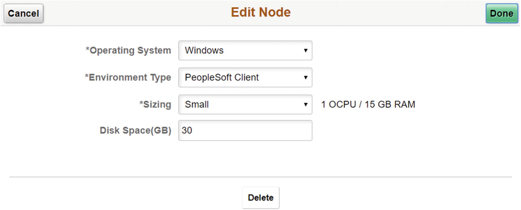
Editing an existing node in a topology
Once the changes you desire are complete, click Done in the upper right corner of the page to save your edits to the node. You will see any changes you made reflected in the Topology Definition page. Click Save at the top of the page to finish saving your topology edits. You should see a message at the top of the page that your edits were successfully saved.
Cloning a Topology
- 1.
Go to the the Topology home page, and select the existing topology you would like to clone by selecting the radio button to the left of the topology name.
- 2.Once the topology is selected, click the Clone button in the top left of the list of topologies (Figure 6-22).
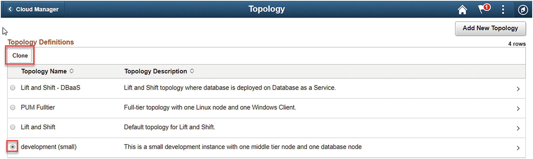 Figure 6-22
Select the topology to clone and click Clone
- 3.Next, provide the new topology with a name. In this example, we are going to clone the development (small) topology for use as a quality assurance (small) topology (Figure 6-23).
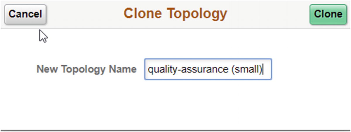 Figure 6-23
Clone Topology
- 4.
Click the Clone button in the top right corner of the window.
- 5.You will now see your newly cloned topology in your list of available topologies. From here you can edit the topology as needed (Figure 6-24).
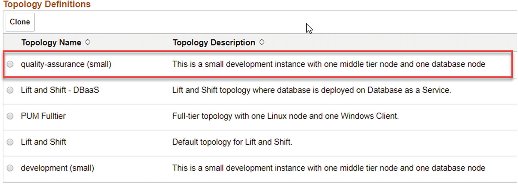 Figure 6-24
Newly cloned topology
- 6.To complete this exercise, we will click the new cloned topology and edit the description to more closely match the name of the topology and save the edits (Figure 6-25).
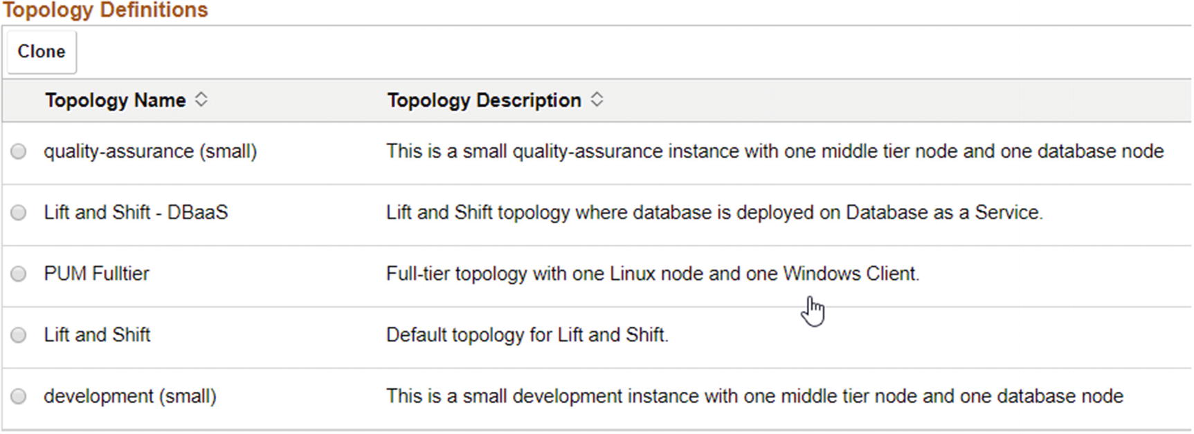 Figure 6-25
Cloned and edited topology
Deleting a Topology
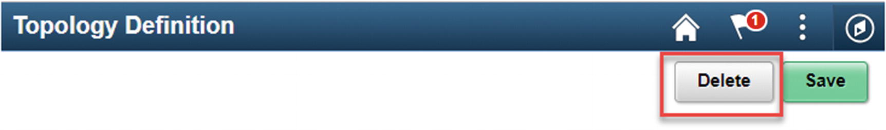
Delete a topology