It might seem that technology-focused teachers would be early adopters of 3D printing. However, particularly in high school, teachers in these subjects often feel they have too much to cover to add anything new. We think this is unfortunate, and that 3D printing has real power to offer alternative ways of learning beyond writing down notes from a whiteboard.
Typically, one of the bigger barriers to using a 3D printer is learning a CAD program. Schools with robotics or engineering programs often teach CAD already, so the students in those programs have a head start. Schools who are considering teaching coding could use OpenSCAD (Chapter 6) as a first language. OpenSCAD’s language is similar to C, Python, Java, and other languages in the “C family,” and is useful for scientific and math models.
No matter the CAD program used, though, creating good math or science models requires deep domain knowledge. Having students who need an extra challenge create models for their fellow students may be an option. We find we learn a lot whenever we dig into creating a model, because typically we have to go beyond textbooks and the 2D projections found in them. In this chapter, we share what we have learned about developing 3D printed math and science models. We also describe applications in robotics, and the issues that arise when you are creating functional parts.
Tip
We have written two books of science and math projects: 3D Printed Science Projects (Apress, 2016) and 3D Printed Science Projects Volume 2 (Apress, 2017). The models are in OpenSCAD and are designed to be a middle ground between designing objects from zero and just downloading something prefabricated. Most of the models have parameters that can be changed to allow the student to explore what happens when the model changes, based on the science involved. The molecule, flower, and wing models we show as examples in this chapter (Figures 9-1 through 9-4) are described in the 2016 book.
Visualization

Ice crystal model (model from 3D Printed Science Projects)
A first question to ask is whether the model you are considering creating really is inherently three-dimensional. We have seen people make flat 3D printed versions of diagrams. You can do that, but why? Other than the particular case of the visually impaired (described in Chapter 12), there is not a clear rationale, and the print will likely be harder to read than a traditional paper print. Even for the visually-impaired community, there are solutions for that sort of thing, like swell paper. For example, 3D printing a periodic table without adding any insights does not make a lot of sense, but there are a lot of periodic table models out there. On the other hand, adding another feature to the table for the third dimension might be interesting, like ones on www.thingiverse.com that use the third axis to show how properties of the elements like reactivity and density vary.
If a concept is abstract and naturally three-dimensional, as long as the relationships among the axes are correct and line up with the math, or physics, or what-have-you being described, a model can bring a lot of insight. Figuring out how to create the model is a learning experience, too, as you (or your students) wrestle with how to have the model’s geometry show the concept you have in mind.
Experiments

Flower growth model (photo and model from 3D Printed Science Projects)

Plant growth model and the real plant (photo and model from 3D Printed Science Projects)
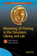
Airfoil model (photo and model from 3D Printed Science Projects)
3D printing is also being used to create low-cost lab equipment. Scientists often are big consumers of duct tape, and 3D printing can create more opportunities to create one-off objects to hold things somehow. Of course, if there are chemicals involved, it becomes necessary to investigate whether or not the 3D printed materials involved are compatible with the chemicals in question. There are various open source science groups out there documenting their solutions, notably Joshua Pierce’s group at Michigan Tech University. They maintain Appropedia ( www.appropedia.org/Open-source_Lab ), which has links to a variety of equipment, particularly for optics. Chapter 13 has more discussion on these topics.
Robotics
The international organization FIRST Robotics (For Inspiration and Recognition of Science and Technology, www.firstinspires.org ) is which is making robotics a school sport, like basketball, with several leagues aimed at different age brackets. At the high school level, teams build robots that might weigh as much as 150 pounds. Many of them use 3D printing for a few components. Common applications are camera mounts and protective (and/or decorative) mounts or cases for small electronics.
Will Kalman coaches a FIRST high school team at Granada Hills Charter High School, the Robodox (Team 599, in FIRST parlance), which has been around for quite some time. When we asked him for an example of a good use of 3D printing, he told us about the part shown in Figures 9-5 and 9-6.
FIRST teams have to build a robot in six weeks and are eligible for awards if during the rest of the year they do community projects, demonstrate their robot at community events, and so on. Thus many teams have an “outreach bot” that may have been an earlier competition robot or could be a cannibalized Frankenstein of several earlier ones.
Currently, the Robodox use a previous year’s robot as their outreach bot. This particular robot needed compressed air for some of its functions. They noticed when doing an outreach event that their air compressor was overheating because they were using it so heavily. It actually got hot enough that it softened a plastic air hose, which subsequently blew out.
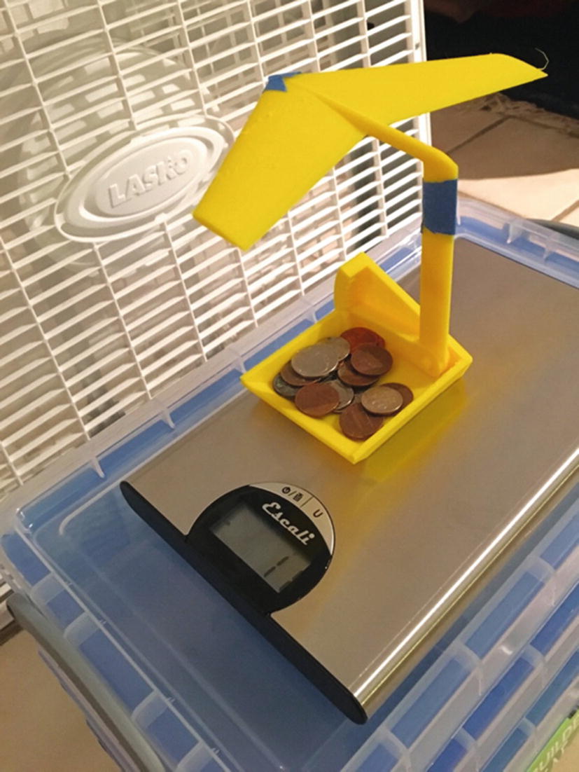
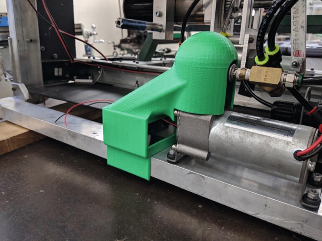
The team decided to add a fan to cool the air compressor to avoid having that happen again. Team member Omeed Shahhosseini designed and implemented the fix shown in Figures 9-5 and 9-6. The new part takes air from a fan and turns the air so that it blows on the compressor to keep it cool. The part also had to fit onto a chassis rail to keep this ductwork oriented correctly and had to be sturdy enough to support the forces involved.
Fan and ducting (model by Omeed Shahhosseini, photo by Will Kalman)
Closeup of fan housing (model by Omeed Shahhosseini, photo by Will Kalman)
Functional Parts
As with the robotics applications we just saw, sometimes a functional part is required—that is, a part that is not just a decorative, standalone piece but one that is part of a bigger project or that is doing something that requires at least some mechanical strength. We know that once students learn a CAD program that can also model forces, they tend to rely on it and believe that if it says a part is strong enough, it is.
However, for 3D printing that can be tricky. For printing with filament, the strength of parts varies a lot based on the manufacturer and variability in the qualities of the filament itself. Some manufacturers now quote strength parameters, but this tends to be based on expensive, specialty filament, typically tested after a tightly controlled printing process of a standard simple part.
People are beginning to attempt to define standards, and there are papers being written on the strength of 3D prints. Appropedia and open-access journal articles it references are a good free source of information to get started, at www.appropedia.org/Tensile_Strength_of_Commercial_Polymer_Materials_for_Fused_Filament_Fabrication_3-D_Printing .
But even if you do have nominal numbers for the strength of a filament and data from other people’s tests, the temperatures used for printing, specifics of the printer, the settings you are using, and the geometry and orientation of the print itself all matter too. As we saw in the “Shells” section of Chapter 3, your slicer will allow you to specify the thickness of the horizontal shell, either as a number of perimeters or in millimeters (which will be rounded to a multiple of your perimeter extrusion width). Two is typically a good number.
The width (in the x-y plane) of this perimeter is the extrusion width, which must be no smaller than your nozzle diameter, and might be larger. For a given extrusion width, if you are using thick layers the interlayer adhesion might not be as good as it would be if you used thin layers, which will be more compressed and have more contact area. If the nozzle temperature is too low, that can lead to worse interlayer adhesion.
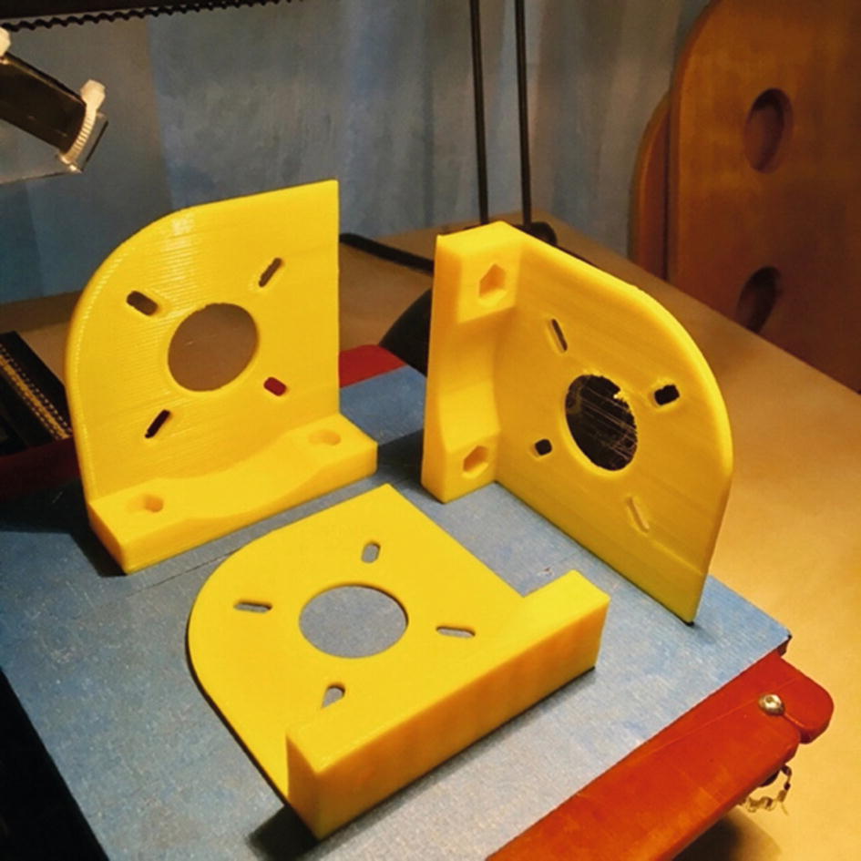
Motor mount printed in three orientations
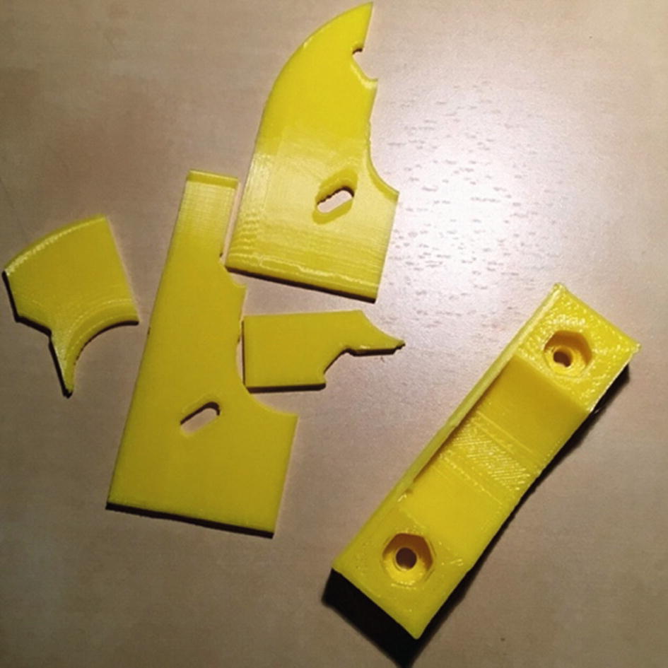
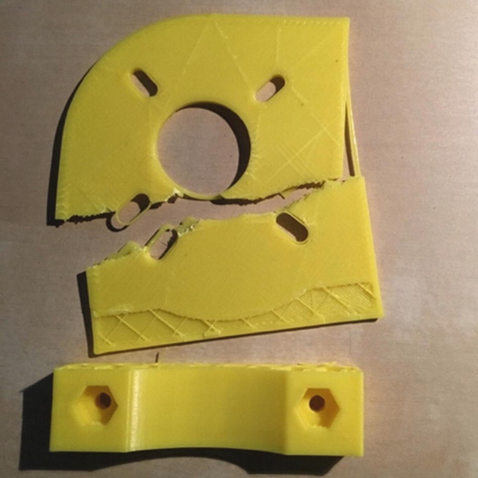
Look carefully at Figure 9-7. Which one of these three parts would you expect to be the strongest and least likely to fail during its intended use? Where are the inter-layer lines?
Caution
This part has been created to be too flimsy for its intended purpose so that we could make a point. It was printed in PLA, with the temperature deliberately a little too low to make this a more spectacular demo.
Motor mount printed vertically, base down
Motor mount printed flat on the plaform, base sticking up

Motor mount printed on its side, layer lines perpendicular to base
These parts were all printed in PLA, so if the motor they were holding got hot (or if we left them on a hot car dashboard in summer), they would warp. UV radiation degrades many plastics, too.
So, what to do? The simplest thing, particularly in a K-12 environment, is to thoroughly test the part before using it for something load-bearing. Consider how hot it will get, whether it will be outside for a long period of time, and so on. Constructing the tests and interpreting the results can be a good project in and of itself, and lends itself to an age-appropriate level. (Of course, if you are going to break things, use eye protection and protect the hands of the person breaking the part.)
Note
Resin prints are more homogeneous than filament-based ones but have their own issues. Resin part strength is critically dependent on following the appropriate post-cure processes, and even then standard resins can be very brittle.
If the exercise of making a functional part is embedded in an engineering class, it is also an opportunity to discuss what to do when the CAD software cannot be completely trusted. We have seen students get upset when a part that “should have been strong enough” (according to the CAD program) snapped instead. Thinking about why this happened and the need to use judgment in addition to software tools might be a memorable lesson. At least, it makes a different point than seeing a lot of parts that did work, but maybe only because the designer got lucky. Chapter 2 has more discussion of materials’ properties to help you think about a good choice given your printer’s capabilities.
Conductive Parts
If you have a printer that can lay down two materials at a time, you may be tempted to use conductive filaments to lay down conductive paths in your part. These filaments are made of PLA or another material with embedded graphite; this makes the filament somewhat abrasive for your nozzle. The graphite makes them mildly conductive, but the resistance can be pretty high. So, if you are trying to carry current—say, to light an LED—its ability to carry enough current might be a little marginal.
Filament manufacturer Proto-pasta, for instance, quotes a volume resistivity for its conductive PLA of 3D printed parts along layers of 30 ohm-cm and across layers of 115 ohm-cm ( www.proto-pasta.com/collections/exotic-composite-pla/products/conductive-pla ). Note that the ohm-cm units indicate that the resistance will be lower if the cross-sectional area of the conductive part of the print is bigger, and lower if the distance current has to travel through the print get smaller. The resistance is proportional to the cross-sectional area divided by that distance. However, if you have an application that does not require a lot of current, such as creating capacitive touch sensors, printing a conductive trace might allow you to create some interesting circuitry embedded in a housing. You could be better off, though, just leaving room to run wire or another conductive material through a gap in your print.
Tip
If you are developing Arduino electronics for a robot or similar project, you can make housings in Tinkercad. Tinkercad now has the ability to simulate a circuit and help you design enclosures around certain electronic components ( www.tinkercad.com/circuits ).
Learning More
The key to using 3D printing effectively in a science or math context is to solve a problem that needs solving. This means it is best to guide the choice of problem for students (or for faculty wanting models) based on math or science needs. This sounds obvious, but for some reason people often start with the tool and try to find an application for it. Try asking yourself, “What would I love to have my students make (or make for my students) that just does not seem possible?” Then see if 3D printing (or another maker technology) can get you partway there.
The recent boom in citizen science projects, where the public participates in real scientific endeavors, may be the next frontier for 3D printing. Currently, most of these projects, like those at www.zooniverse.org , are focused on having the public take or interpret images. But we and others have been trying to help scientists think about having people take data for them in other ways, perhaps involving creating DIY instrumentation plans that someone can download and print. There are issues there to be sure (standardization, for one) that need to be worked out, but in principle it might be an exciting new area for citizen science.
We are particularly interested in finding ways to teach math differently using the types of model we talk about in this chapter. You can check out our Hacker Calculus project, which is reimagining calculus teaching by taking advantage of 3D prints, at https://hackaday.io/project/20621-hacker-calculus .
We have also been inspired by Paul Lockhart’s book A Mathematician’s Lament (Belleview Literary Press, 2009). Written by a mathematician who teaches at the high school level, the book discusses how to teach math intuitively. He has several other books, too, about ways of teaching math with less notation and more understanding.
Summary
In this chapter, we discussed how to use 3D printing to create math and science visualizations, and to enable experimentation. Robotics teams and engineering classes can use the technology to solve real-world problems, and to discover the limits of modeling and prediction for materials that are not the same throughout a part. Specialty filaments, like conductive ones, might open other experiment opportunities. Finally, we noted that 3D printing and other maker technologies can open up new opportunities for teachers, students, and other members of the public to take part in real scientific explorations.